S3 Graphics S3G002 Part 15 Class B Peripheral Device- Graphic Card User Manual 2
S3 Graphics Co., Ltd. Part 15 Class B Peripheral Device- Graphic Card Users Manual 2
Contents
- 1. Users Manual 1
- 2. Users Manual 2
Users Manual 2
User Guide for Chrome 500 Series Graphics
SG195-A.1 10/20/2008
Page 71
Extend Desktop
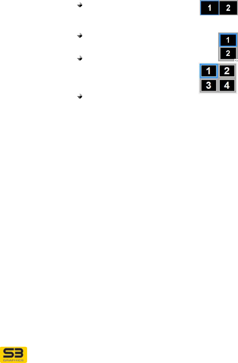
layout There are three radio buttons provided as an aid to
relative positioning of the multiple displays in an extended
desktop configuration:
Select Horizontal to arrange the
desktop in a horizontal row with the
Primary display (1) positioned on the left and the
secondary (2) on the right.
Select Vertical to arrange the desktop in a
vertical row with the Primary display (1)
positioned above the secondary (2).
Select Grid when you have four displays
to arrange in a grid pattern. If only
two displays are present, selecting
Grid will result in a Horizontal
arrangement.
If Other appears as a grayed out
layout option, then the layout has been previously
adjusted through the operating system’s Display
Settings page, and the layout does not exactly
match the other 3 available choices on this dialog.
You cannot select this option, it is informative only.
User Guide for Chrome 500 Series Graphics
SG195-A.1 10/20/2008
Page 72
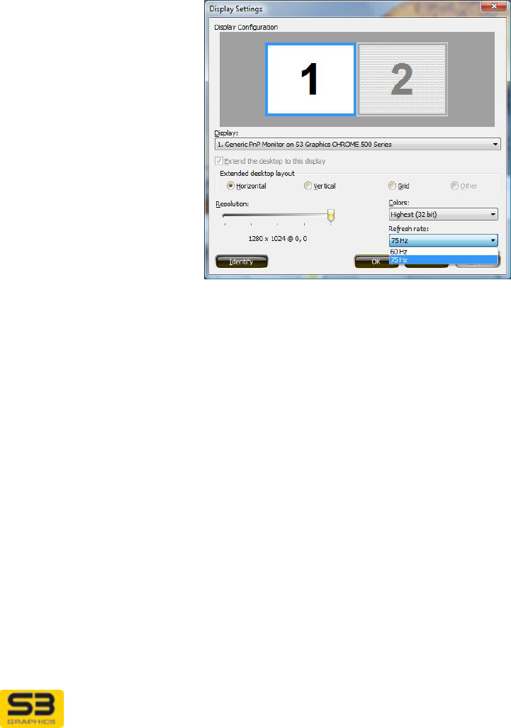
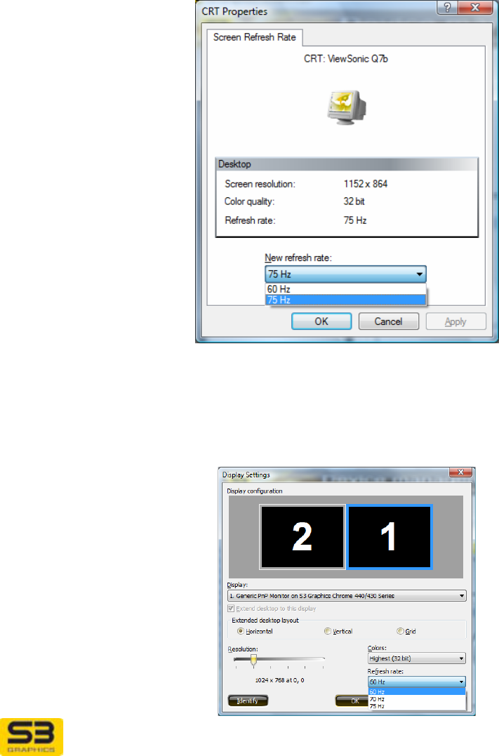
Refresh rate… From the Options dropdown list, select Display
settings… Near the lower right corner, click the Refresh
rate… dropdown list to select a refresh rate from the
available refresh rates for the display device icon outlined
in blue which represents the current output display device.
The operating system will test the selected refresh rate
and you will have the option to accept or decline the
change.
User Guide for Chrome 500 Series Graphics
SG195-A.1 10/20/2008
Page 73
7.3 Fine Tuning CRT
When your display device is detected as a connected and active CRT, you can
configure the CRT using the S3 ScreenToys Device Management page.
Adjustments you make are remembered by the S3 Graphics software even when
your system is sleeping or rebooted.
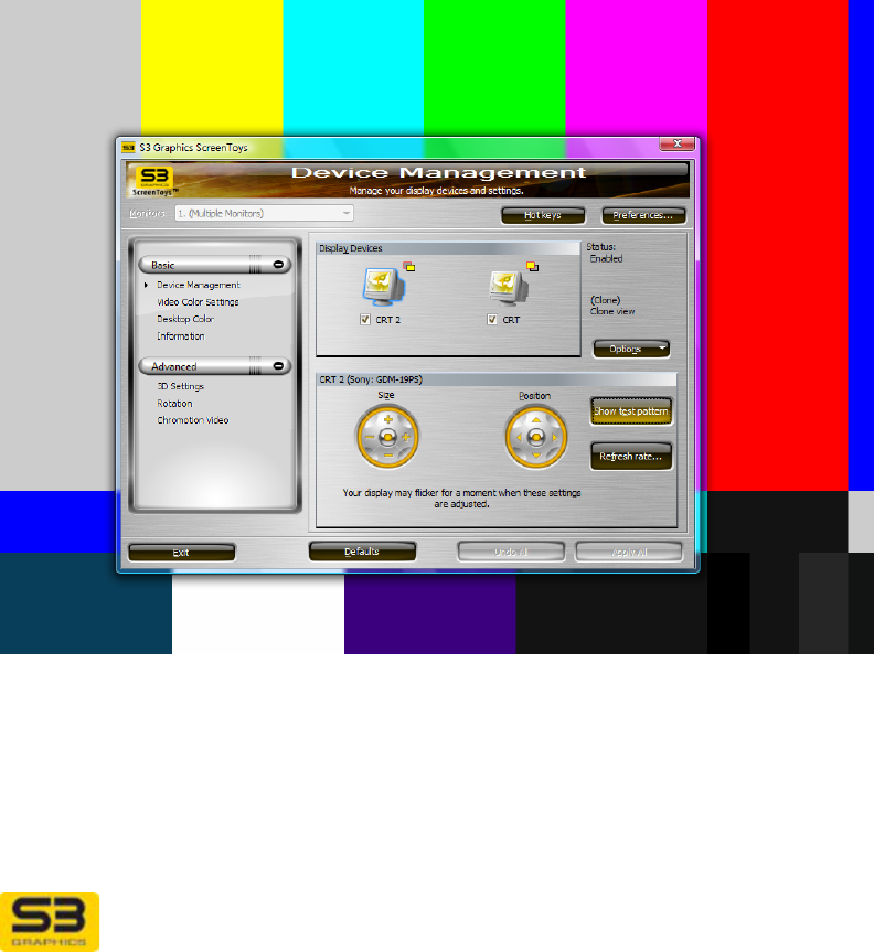
ACCESS: To adjust CRT, right click on the desktop and click from the menu to
select S3 ScreenToys. In the left menu column, select Basic, Device
Management. In the Display Devices area, click the CRT icon. Next check the
Device Status checkbox underneath the icon. When the selected device icon
has a blue outline and checked box, available options for the device can be
configured. The lower Device Settings: CRT area will show available options for
CRT configuration.
OPTIONS:
Options for CRT adjustment may include:
User Guide for Chrome 500 Series Graphics
SG195-A.1 10/20/2008
Page 74
Device Settings:
CRT model info &
settings area
The Device Settings title row will report the manufacturer
name and model detected for the selected display
device.
The following options may be available for adjustment
for the selected CRT.
NOTE: If using multiple monitors, you must exit
Extended desktop mode for these settings to be
available.
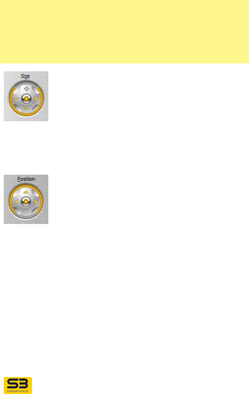
Size
The Size controls allow you to increase and decrease
the horizontal and vertical size of the display image. This
does not change the actual desktop size, but rather uses
the hardware to stretch or shrink the visible image.
Click the plus signs to increase the horizontal or vertical
size.
Click the minus signs to decrease size.
Click the middle round button to reset both horizontal
and vertical size to the default values.
Most monitors have a similar control built in.
Position
The Position control allows you to move the monitor
image position to suit your individual preference and
monitor.
Click the plus signs to move the image position up or to
the right on the monitor.
Click the minus signs to move the image towards the
left or the bottom of the monitor.
Click the middle round button to reset the image
position to the default values.
Most monitors have similar controls built in.
Test Pattern If a test pattern button is accessible, you can click the
Test Pattern button to cycle through various test
patterns to help you calibrate and adjust the CRT image.
In order, the patterns are:
SMPTE color bars, alignment patterns (to help with
scaling and aspect ratio adjustments), and red, green,
and blue backgrounds.
Other CRT features can be adjusted while Test Pattern
backgrounds are displayed.
User Guide for Chrome 500 Series Graphics
SG195-A.1 10/20/2008
Page 75
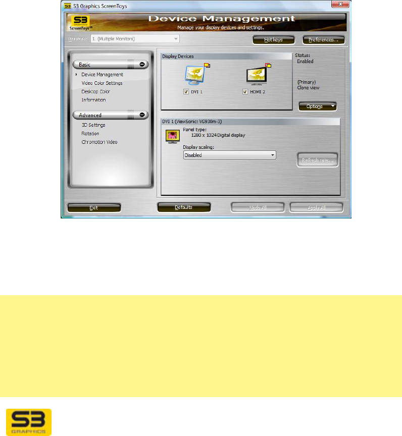
Refresh rate… Click the Refresh rate… button. The CRT Properties
Screen Refresh Rate window will appear. Select a
refresh rate from the dropdown list of available refresh
rates for the current output display device. Click Apply
to apply your change. The operating system will test the
selected refresh rate and you will have the option to
accept or decline the change.
Alternately, from the Options dropdown list, you can
select a refresh from the Display settings Display
configuration window which also has a Refresh rate…
dropdown list to select a refresh rate from the available
refresh rates for the current output display device, as
represented by the display device icon outlined in blue.
User Guide for Chrome 500 Series Graphics
SG195-A.1 10/20/2008
Page 76
7.4 Fine Tuning DVI
When a DVI is detected as connected and active, you can configure the DVI
using S3 ScreenToys Device Management page. Adjustments you make are
remembered by the S3 Graphics software even when your system is sleeping or
rebooted.
ACCESS: To adjust DVI, right click on the desktop and click from the menu to
select S3 ScreenToys. In the left menu column, select Basic, Device
Management. In the Display Devices area, click the DVI icon. Next check the
Device Status checkbox underneath the icon. When the selected device icon
has a blue outline and checked box, available options for the device can be
configured. The lower Device Settings: DVI area should show options for DVI
configuration.
OPTIONS:
Options for DVI adjustment vary with the type of DVI. If your multi-sync DVI
reports itself as a CRT, then the CRT options will appear as associated with the
device.
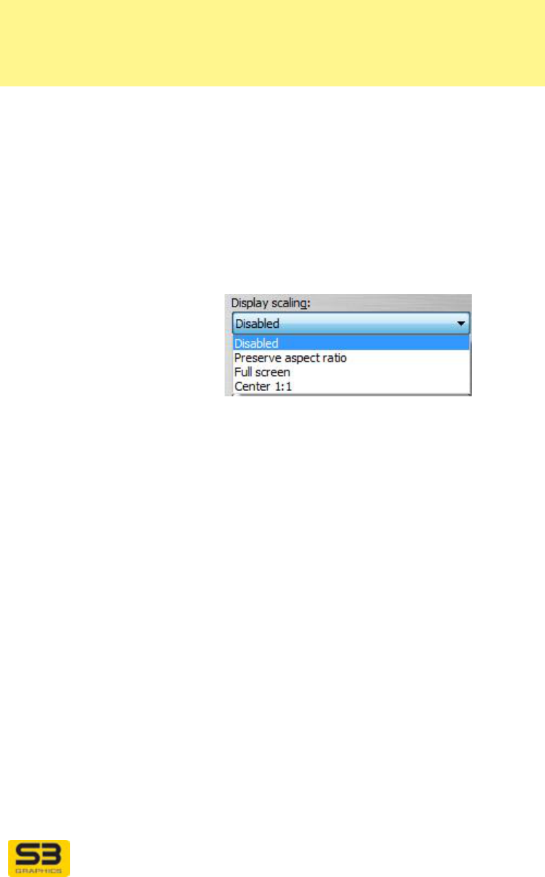
Device Settings:
DVI model info &
settings area
Reports DVI specific information.
The DVI Settings area title row will report the
manufacturer name and model detected for the selected
display device.
Options described below do not appear in the DVI
Settings area if the option is not supported for the
User Guide for Chrome 500 Series Graphics
SG195-A.1 10/20/2008
Page 77
selected DVI device. For example, if the Expansion
options are dimmed or do not appear, then the
expansion options listed below are not configurable for
this DVI device instance at the current resolution.
Panel Type Details the physical size (in pixels) and panel type of the
device selected.
Display Scaling
image icon The icon shows an example of the currently checked
Display scaling option. Change the Display scaling
option to observe the change in screen size that results
from changing the Display scaling setting.
Display scaling
dropdown list
The Display scaling dropdown list allows you to let S3
Graphics software help set an optimized mode for your
DVI output.
Preserve aspect ratio is the default setting. The S3
Graphics software will maintain the aspect ratio and up
scale the screen image as large as possible to the
device’s native resolution.
Note: Even if you have enabled the monitor’s built-in
scaling, the monitor’s scaling will not occur. The S3
Graphics driver does the expansion to the native display
resolution.
Select the Disabled list item to have S3 Graphics
software use the display resolution and refresh rate
requested you specify, without any GPU up scaling. This
setting is appropriate when you want to use the
monitor’s built-in scaling.
Select the Full screen list item to have S3 Graphics
software upscale the screen image to a full screen
image which matches the device’s native resolution. The
aspect ratio may not be maintained.
Select the Center 1:1 list item to have S3 Graphics
software use the GPU upscale hardware to center the
display but do not do any upscaling.
User Guide for Chrome 500 Series Graphics
SG195-A.1 10/20/2008
Page 78
Preserve aspect
ratio Select the Preserve aspect ratio checkbox to ensure the
desktop image always maintains its original aspect ratio,
or relationship between the horizontal and vertical size
(in pixels).
For example, if you have a wide screen panel you might
choose not to maintain the aspect ratio and thereby
allow the S3 Graphics hardware and software to
horizontally expand the image to fit the wide panel size.
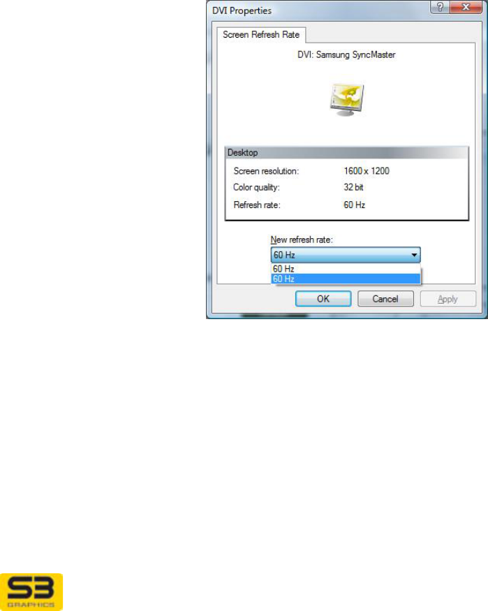
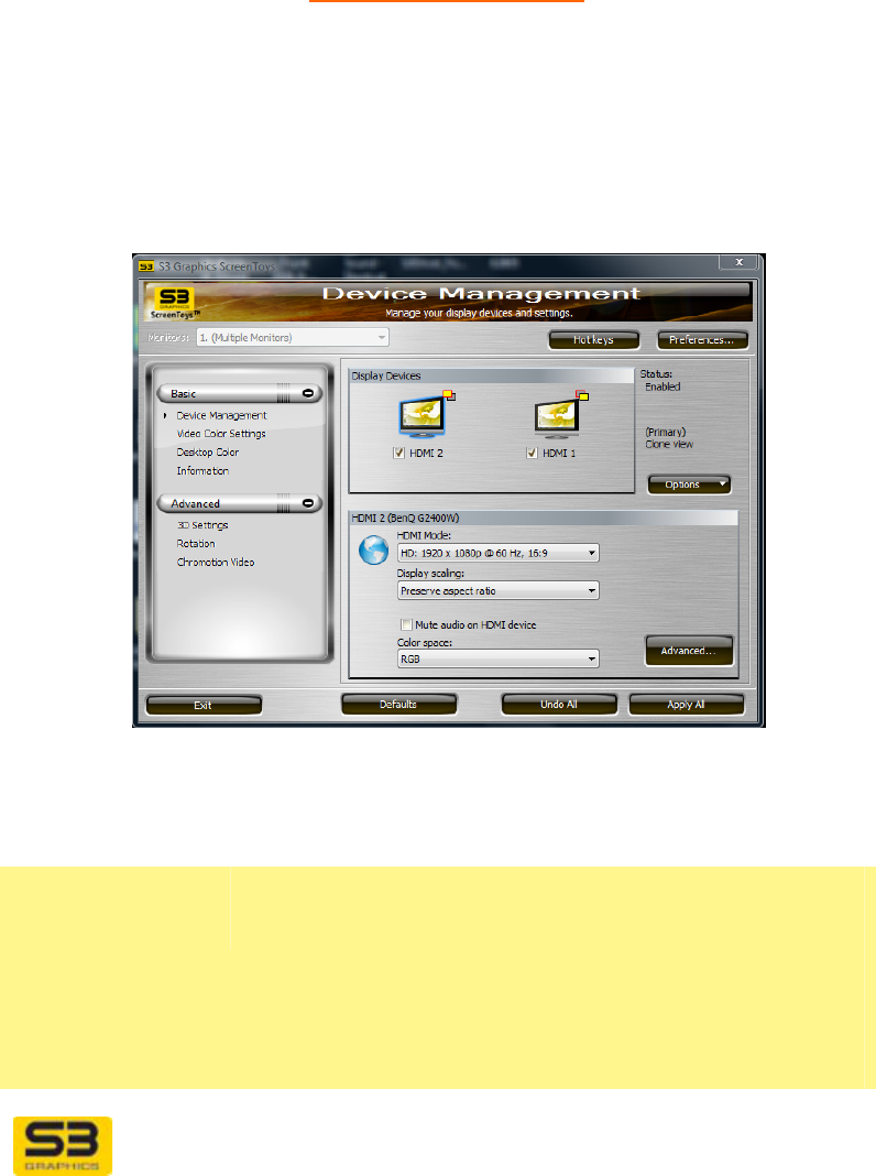
Refresh rate… Click Refresh rate… to launch the S3 Graphics Screen
Refresh Rate window. Under Windows Vista and
Windows XP you can use the utility to select from a
dropdown list of refresh rates for the current output
display device.
User Guide for Chrome 500 Series Graphics
SG195-A.1 10/20/2008
Page 79
7.5 Fine Tuning HDMI
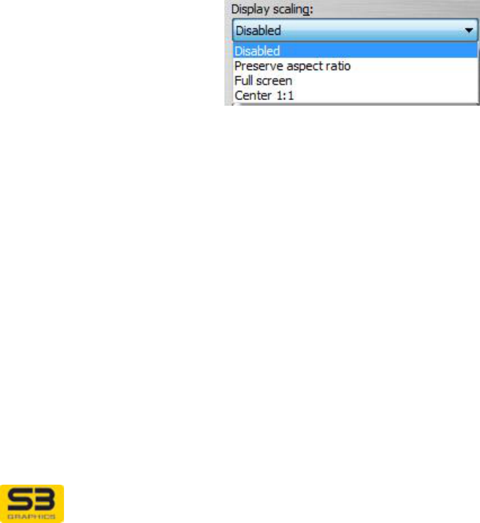
When an HDMI display device is detected as connected and active, you can
configure HDMI using S3 ScreenToys Device Management.
Note: S3 HD Audio must also be configured to ensure a satisfactory sound and
video synchronization. See Fine Tuning S3 HD Audio for detail.
ACCESS: To adjust HDMI, right click on the desktop and click from the menu to
select S3 ScreenToys. In the left menu column, select Basic, Device
Management. In the Display Devices area, click the HDMI icon. Next check the
Device Status checkbox underneath the icon. When the selected device icon
has a blue outline and checked box, available options for the device can be
configured. The lower HDMI Settings: area will show available options for HDMI
configuration.
OPTIONS:
The following options may be available for HDMI display output configuration:
Device Settings:
HDMI model info &
settings area
The HDMI Settings area title row will report the
manufacturer name and model detected for the selected
HDMI display device.
The following configuration options are available when
the HDMI device is connected and enabled and the
HDMI Device icon is selected.
User Guide for Chrome 500 Series Graphics
SG195-A.1 10/20/2008
Page 80
HDMI Mode
dropdown list HDMI Mode is a dropdown list of available HDMI
Formats.
This list is dynamically generated information
processed by the driver from data specified in the
HDMI monitor’s information. The driver also prunes
the list to those formats which do not exceed the
graphic board’s available digital interface
bandwidth.
Note: If you have a 16:9 wide screen device, 4:3
formats will appear on your screen with black areas
on the left and the right of the screen. If you have a
4:3 standard screen, 16:9 format types will appear
on your screen in letter-box mode, i.e., with black
areas on the top and the bottom of the screen.
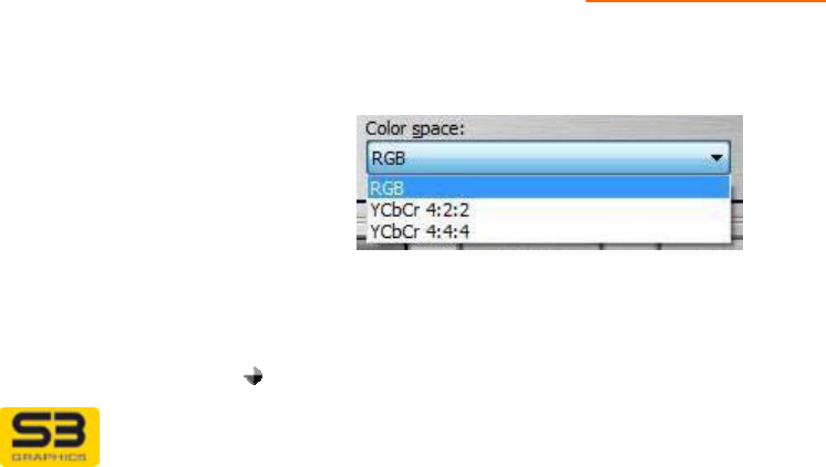
Display scaling
dropdown list
The Display scaling dropdown list allows you to let S3
Graphics software help set an optimized mode for your
HDMI output.
Preserve aspect ratio is the default setting. The S3
Graphics software will maintain the aspect ratio and up
scale the screen image as large as possible to the
device’s native resolution.
Note: Even if you have enabled the monitor’s built-in
scaling, the monitor’s scaling will not occur. The S3
Graphics driver does the expansion to the native display
resolution.
Select the Disabled list item to have S3 Graphics
software use the display resolution and refresh rate
requested you specify, without any GPU up scaling..
This setting is appropriate when you want to use the
monitor’s built-in scaling.
Select the Full screen list item to have S3 Graphics
software upscale the screen image to a full screen
image which matches the device’s native resolution. The
aspect ratio may not be maintained.
User Guide for Chrome 500 Series Graphics
SG195-A.1 10/20/2008
Page 81
Select the Center 1:1 list item to have S3 Graphics
software use the GPU upscale hardware to center the
display but do not do any upscaling.
Note: If you have set and saved a Custom Mode for this
device, the Custom Mode will be used, regardless of the
current Display scaling setting.
Auto Mode
checkbox
(Windows XP only)
The Auto Mode checkbox allows you to let S3
Graphics software own the selection of the optimized
mode for your HDMI-output.
Select the Auto Mode checkbox to have S3 Graphics
software automatically determine which HDMI Type is
optimized for your configuration.
Clear the Auto Mode checkbox if you want to decide
which HDMI Type should be selected. (This is the
current default setting for Windows XP. For Windows
Vista this option is not applicable.)
Mute S3 HD Audio
device checkbox The Mute S3 HD Audio device checkbox allows you
direct access to mute the audio portion of the HD audio-
video stream.
Select the Mute S3 HD Audio device check box to mute
the audio portion of the merged HD-formatted audio-
video stream.
Clear the Mute S3 HD Audio device checkbox to allow
the audio portion of the stream to play.
Note: For further information on S3 HD Audio control,
refer to the following section on Fine Tuning HD Audio.
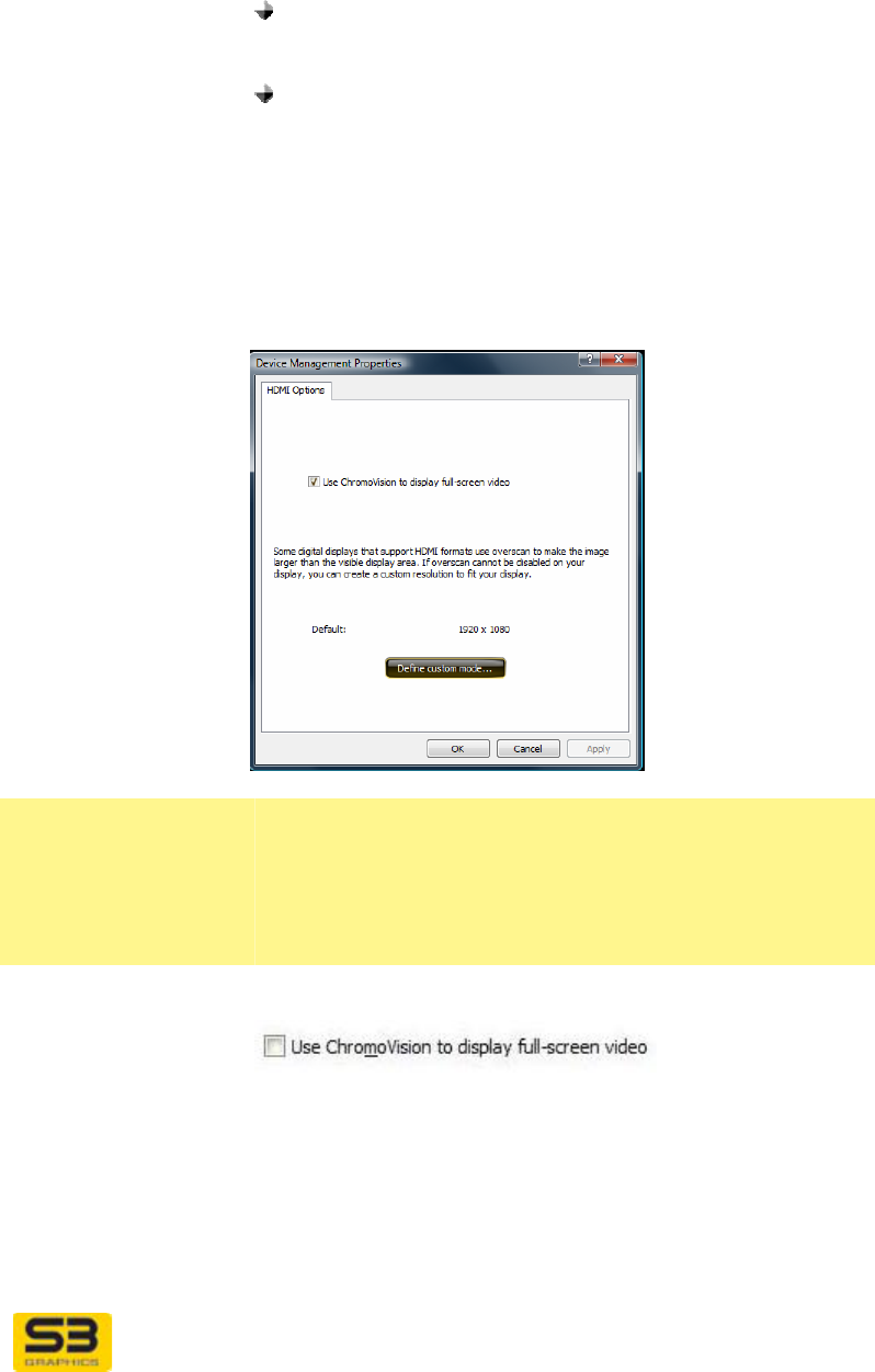
Color space
dropdown list The Color space dropdown list allows you to select
between three formats for your HDMI output. Video
pixels can be encoded in either RGB, YCbCr 4:4:4 or
YCbCr 4:2:2 formats.
Use this option when the output on the screen doesn’t
appear as expected.
Select:
RGB. RGB encoding is the default. It can be used for
User Guide for Chrome 500 Series Graphics
SG195-A.1 10/20/2008
Page 82
color depths of 24-bit and above.
YCbCr 4:4:4. It can be used for color depths of 24-
bit and above, and may provide greater color
sampling.
YCbCr 4:2:2. This format is not supported for color
depths greater than 24-bits.
Advanced… Click the Advanced button to open the HDMI Options
page.
7.5.1 Advanced: HDMI Options
HDMI Options
page These additional HDMI configuration options are
available for selection through the HDMI Options
window, accessible from the Advanced button located in
the HDMI settings area of the S3 ScreenToys Device
Management window.
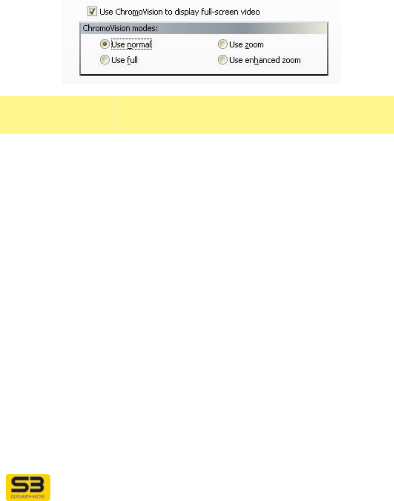
Use ChromoVision
to display full-
screen video
Click Use ChromoVision to display full-screen video)
checkbox to enable ChromoVision.
When you are using Windows Vista or Windows XP,
ChromoVision allows full screen playback on your HDMI
device while windowed video plays on another display
device associated with the Primary View. ChromoVision
is not available when there is only one display output
device, and is not available when you Extend the
desktop. You must be in Clone view.
User Guide for Chrome 500 Series Graphics
SG195-A.1 10/20/2008
Page 83
Refer to the Video Enthusiast section for additional
information about ChromoVision.
Overscan note The Options page includes text advising the user that
they may have the option to set a custom resolution for
their display.
Default: This area provides the default resolution for your HDMI
device.
Define custom
mode… button Click the Define custom mode… button to open a
dialog window which allows you to customize your HDMI
desktop size.
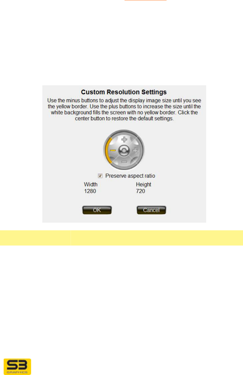
HDMI Define
custom mode This control occupies the full area for the device on the
desktop
Custom
Resolution
Settings:
Size
The Custom Resolution Settings control button allow
you to increase and decrease the horizontal and vertical
size of the display image. This does not change the
actual desktop size, but rather uses the hardware to
stretch or shrink the image visible on the HDMI.
Click the plus signs to increase the horizontal or vertical
size.
Click the minus signs to decrease size.
Click the middle round button to reset both horizontal
and vertical size to the default values.
Note: If the Size control is dimmed, size should be
adjusted using the Display Settings or CHROME menu

User Guide for Chrome 500 Series Graphics
SG195-A.1 10/20/2008
Page 84
desktop resolution adjustments.
Additional video sizing adjustment control is usually
available through the video quality controls built into the
HDMI itself.
Preserve aspect
ratio Select the Preserve aspect ratio check box to ensure
the HDMI image always maintains its original aspect
ratio (proportional relationship) between horizontal and
vertical size.
If the Preserve aspect ratio box is checked (default),
the aspect ratio is fixed (locked), the horizontal size
controls are disabled and you will only be able to adjust
the vertical size. Any adjustment made to the vertical
size of the display automatically causes an adjustment of
the horizontal size necessary to maintain the existing
aspect ratio.
If this box is not visible or dimmed, this option is not
available for your configuration.
Restore Default
Click the middle round yellow button to return to the
default HDMI size settings.
OK, Cancel Click OK to apply the changes and exit. Click Cancel to
exit the dialog without making any changes.

User Guide for Chrome 500 Series Graphics
SG195-A.1 10/20/2008
Page 85
7.6 Fine Tuning S3 HD Audio
Microsoft Windows Vista includes an HD Audio software driver. After the
installation of the S3 video driver, S3 HD Audio will be available for selection as
the default audio device. If the video driver is removed, then HD Audio will not be
available.
Note: If your video board does not include a connection for HDMI or DP, your
board may not support S3 HD Audio.
The audio volume control for video is usually adjusted either through the video
playback application, or through the audio output device.
You may wish to select your S3 HD Audio device as the default sound device. If
you do not, there will be no S3 HD Audio sound. Note that if you want to stop
using the S3 HD Audio you need to set another audio device as default.
To select S3 HD Audio device in Windows Vista:
• Open Control Panel. Select Hardware and Sound.
• Next select Sound and on the Playback tab you will see the available sound
devices.
• Select the desired HD Audio device and Set as Default device.
To select S3 HD Audio device in Windows XP:
• Be sure you have installed Service Pack 3.
• Open Control Panel. Select Sound.
• On the Playback tab you will see the available sound devices.
• Select the desired HD Audio device and Set as Default device.
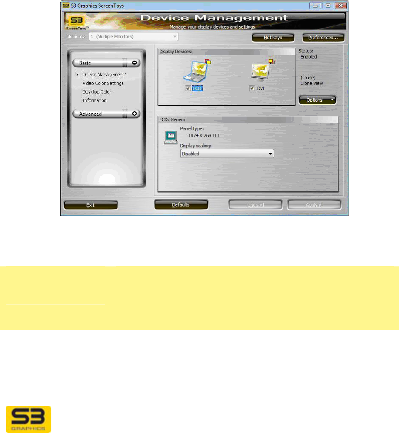
User Guide for Chrome 500 Series Graphics
SG195-A.1 10/20/2008
Page 86
7.7 Fine Tuning LCD
When the mobile system’s LCD panel is detected as connected and active, you
can configure the LCD using the S3 ScreenToys Device Management.
Adjustments you make are remembered by the S3 Graphics software even when
your system is sleeping or rebooted.
ACCESS: To adjust LCD, right click on the desktop and click from the menu to
select S3 ScreenToys. In the left menu column, select Basic, Device
Management. In the Display Devices area, click the LCD icon. Next check the
Device Status checkbox underneath the icon. When the selected device icon
has a blue outline and checked box, available options for the device can be
configured. The lower LCD settings area will show available options for LCD
configuration.
OPTIONS:
The following options may be available for fine tuning for LCD display output:
Device Settings:
LCD model info &
settings area
Reports LCD specific information.
If the manufacturer and model of the LCD is available, it
will be reported in the title row of this area.
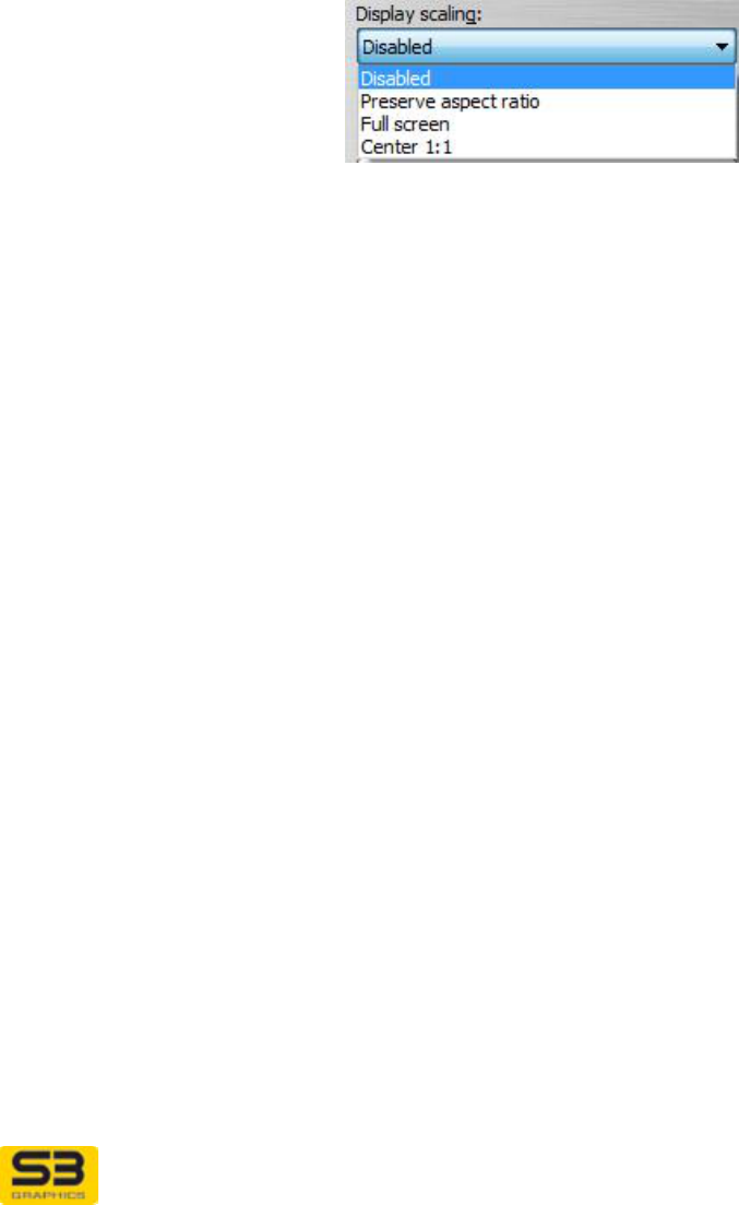
Panel Type Provides the native physical horizontal and vertical size
(in pixels) as well as the type of panel device that is
currently selected.
Display Scaling
image icon The icon shows an example of the currently checked
Display scaling option. Change the Display scaling
User Guide for Chrome 500 Series Graphics
SG195-A.1 10/20/2008
Page 87
option to observe the change in screen size that results
from changing the Display scaling setting.
Display scaling
dropdown list
The Display scaling dropdown list allows you to let S3
Graphics software help set an optimized mode for your
LCD output.
Preserve aspect ratio is the default setting. The S3
Graphics software will maintain the aspect ratio and up
scale the screen image as large as possible to the
device’s native resolution.
Note: Even if you have enabled the monitor’s built-in
scaling, the monitor’s scaling will not occur. The S3
Graphics driver does the expansion to the native display
resolution.
Select the Disabled list item to have S3 Graphics
software use the display resolution and refresh rate
requested you specify, without any GPU up scaling. This
setting is appropriate when you want to use the
monitor’s built-in scaling.
Select the Full screen list item to have S3 Graphics
software upscale the screen image to a full screen
image which matches the device’s native resolution. The
aspect ratio may not be maintained.
Select the Center 1:1 list item to have S3 Graphics
software use the GPU upscale hardware to center the
display but do not do any upscaling.

User Guide for Chrome 500 Series Graphics
SG195-A.1 10/20/2008
Page 88
SECTION 8 MORE DISPLAY SPECIFIC PAGES
In addition to the S3 ScreenToys Device Management settings page, the Basic
and Advanced menus provide access to general information about the graphics
subsystem and pages which provided settings to control Desktop Color and
Desktop orientation, Power management controls for power-sensitive systems,
Color and Chromotion filter controls for video, and Direct3D and OpenGL
controls for 3D. These controls are discussed in the next sections.
This section discusses two additional controls which are device-specific:
Desktop Color
Rotation
Later sections will cover those controls which are applied globally and are not
affected by the configuration of the attached displays.
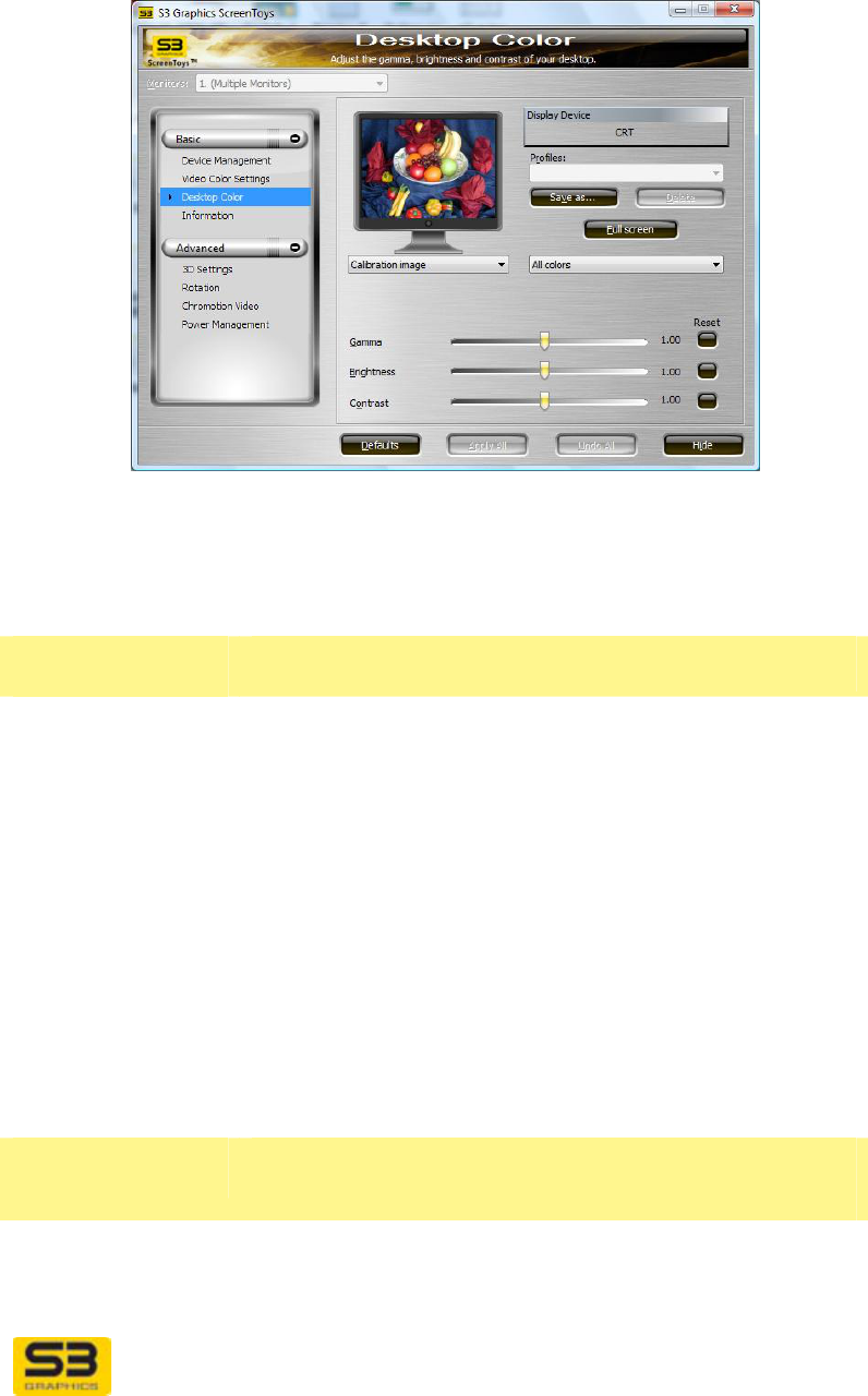
8.1 S3 ScreenToys Desktop Color
With S3 ScreenToys Desktop Color settings you can adjust the gamma,
brightness, and contrast of the GPU output signal to compensate for differences
between different DVI, CRT, HDMI and other display output devices. Different
display output devices will display the same output at different intensities, or
different levels of brightness, contrast and color.
You can make adjustments to Desktop color settings and then create and save
“profiles” or named collections of settings. Independent Desktop Color settings
can be applied for each current active display device when you have selected
multiple monitor Extend the Desktop using both of the GPU’s internal graphics
engines. If you choose not to configure Desktop Color settings yourself, default
settings are built into the software and are optimized for typical display devices.
ACCESS: To adjust Desktop Color for the active displays, right click on the
menu to select S3 ScreenToys, and then in the left menu panel, click Basic,
Desktop Color. The S3 ScreenToys Desktop Color page is also accessible
from the CHROME® menu accessible by right click on the S3 taskbar icon.
User Guide for Chrome 500 Series Graphics
SG195-A.1 10/20/2008
Page 89
OPTIONS:
Select the display for which you want to adjust color from the Monitors:
dropdown list in the upper left of the S3 ScreenToys Desktop Color page.
Configuration options include:
Display
dropdown list
This dropdown list menu will contain the configurable
displays.
Monitors: If only one display monitor is connected, this list will not
be visible. In Clone multiple monitor mode, the list will be
grayed and not selectable.
If two display monitors are connected, a dropdown
monitor list will be available for selection. Click the
arrow to the right of the Monitors: dropdown list menu
to show all connected display output devices (monitors).
The Monitors dropdown list will contain the device name,
if detected. Each display device will be further identified
shown as "N. Display device name", where N is a
number starting from 1. Select the device whose desktop
color you wish to configure. (You can test the selection
by experimentally moving a slider to detect which
monitor is currently configurable.)
Example and
Profiles area
This area displays an image to help you during the color
adjustment process and configuration profile controls.
Display Device The Display Device box on the right of this area will
report which display is the current configurable device,
by device type. You can change the configurable device
from the Monitors dropdown list if it is available.
User Guide for Chrome 500 Series Graphics
SG195-A.1 10/20/2008
Page 90
Calibration
monitor image This "monitor" image will display an image you select
from the list of calibration images. The visual reference
is intended to help you adjust the color.
Calibration
image list Click the arrow to the right of the Calibration image
dropdown list to display a menu of calibration pictures
available to display in the calibration monitor image.
Clicking on the monitor image repeatedly will also cycle
through the calibration images. Click on the image you
want. Pictures include:
Color curves display the gamma curve(s). This is
the default.
Calibration image shows a photographic image with
many shades of red, green, and blue. The image
gives a good "life-like" reference.
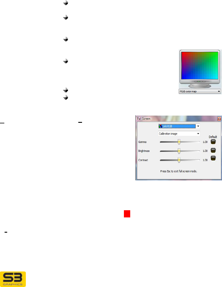
RGB color map shows a grid of colored squares
that span a good range of RGB
values.
RGB color ramp shows dark to
light stripes each of red, green,
blue, and white to allow better
adjustment of contrast.
Color bars 75% and 100%
A number of solid colors at 100% and 75%
saturation levels are also available.
Full screen
button Click Full Screen to
show the current
calibration picture in
full-screen. A miniature
version of the Desktop
color settings window
is shown on top of the
full screen calibration
image. Full screen
mode is useful when running displays at high resolutions
with small font sizes, where the calibration image area
may appear very small in normal mode.
Press Esc or click on U to close the Full Screen dialog.
Profiles Desktop Color profiles are global in nature, meaning that
all schemes created at any time, using any display
adapter, can be selected, even though different display
adapters will have their own settings.
Click on the arrow to the right of the Profiles dropdown
User Guide for Chrome 500 Series Graphics
SG195-A.1 10/20/2008
Page 91
list to see the menu of all Desktop Color Profiles
available for selection. Click on a profile to select it.
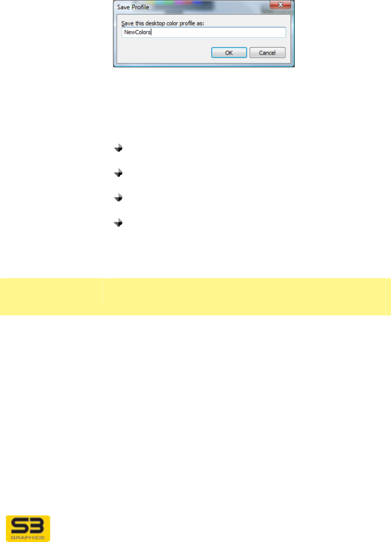
Save as… Click Save As… to save the current settings using the
existing Profile name or a new name. Click OK to
complete the save.
Delete Click Delete to delete the currently selected Desktop
Color Profile.
Adjustment list Click the arrow to the right of the Calibration dropdown
menu to show a list of color channel(s) to adjust.
Select Red to make further adjustments only to the
red channel.
Select Green to make further adjustments only to the
green channel.
Select Blue to make further adjustments only to the
blue channel.
Select All colors to make further adjustments to all
three channels together. For example, green and
blue adjustments will be changed to match the
adjustment for red.
Desktop Color
sliders
Use the three sliders controls in Desktop Color to
change gamma, brightness, and contrast.
Gamma slider Drag the slider thumb along the slider bar to the right to
increase the intensity of the color in the display output.
Drag the slider bar to the left to decrease the color
intensity of the display output.
Brightness slider Drag the slider thumb along the slider bar to the right to
increase the luminance or amount of light in the display
output. Drag the slider bar to the left to decrease the
brightness and darken the display output.
Contrast slider Drag the slider thumb along the slider bar to the right to
increase the level of difference between the light and
dark areas of the display output. Drag the slider bar to
the left to decrease the amount of contrast in the display
output.

User Guide for Chrome 500 Series Graphics
SG195-A.1 10/20/2008
Page 92
Reset buttons Click the black Reset button to the right of the slider to
Reset the value for the individual slider to its default.
Defaults Click the Defaults button at the bottom of the window to
return all gamma, brightness, and contrast settings to
the default for the current display Monitor.
User Guide for Chrome 500 Series Graphics
SG195-A.1 10/20/2008
Page 93
8.2 S3 ScreenToys Rotation
Rotation of the desktop screen image is available through the S3 Graphics S3
ScreenToys Rotation page.
ACCESS: To rotate your desktop screen image, right click on the desktop and
select to open the S3 ScreenToys window. In the left menu column, select
Advanced, Rotation. The S3 ScreenToys Rotation orientation options are now
available for selection. Rotation control is also accessible from the S3 taskbar
icon menu.
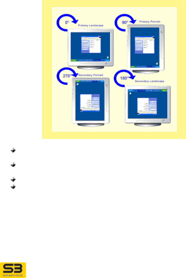
Image Positions
Portrait images are greater in the vertical direction than the horizontal,
and
Landscape images are greater in the horizontal direction than in the
vertical direction.
Primary refers to the main or normal screen orientation position.
Secondary orientations are 180 degrees off the Primary.
When the screen is rotated, the cursor also rotates in sync with the screen
orientation to maintain the same frame of reference as the desktop.
User Guide for Chrome 500 Series Graphics
SG195-A.1 10/20/2008
Page 94
Monitor orientation options:
OPTIONS:
Each connected and enabled device may be rotated independently. The Display
to be changed can be selected through the Monitors: dropdown list located in
the upper left corner of the S3 ScreenToys Rotation page. S3 ScreenToys
Rotation options are:
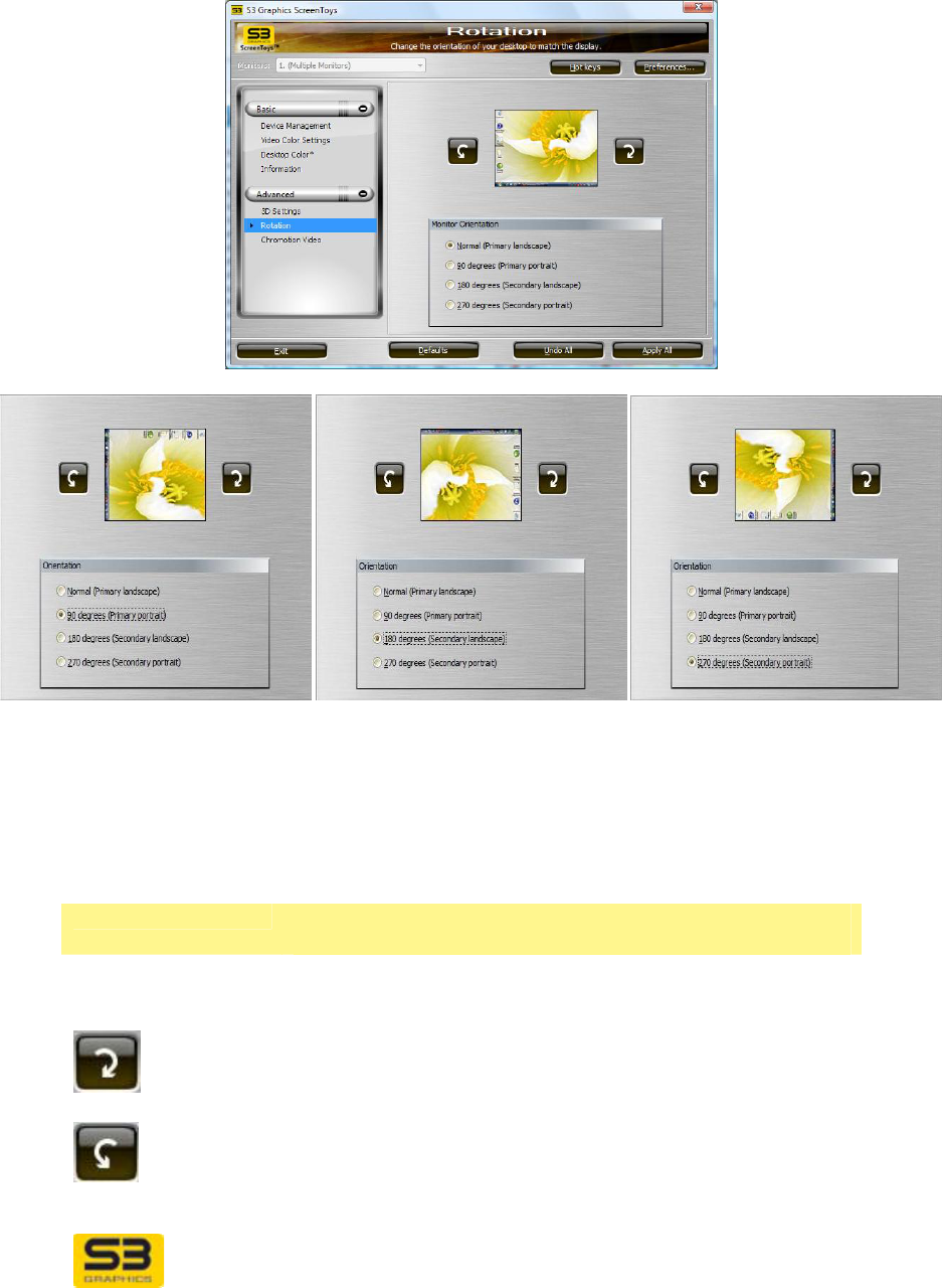
Image area Use this group to step through orientation options and
view the result.
Orientation
reference image View this bitmap image of a desktop to see the effects of
any proposed screen orientation selection.
CW
Click CW once to rotate the sample screen image
clockwise 90 degrees.
CCW
Click CCW once to rotate the sample screen image
counter-clockwise 90 degrees.

User Guide for Chrome 500 Series Graphics
SG195-A.1 10/20/2008
Page 95
Orientation area This group contains four radio buttons, one for each of
the orientations available for selection.
Normal (Primary
landscape) Click the Normal (Primary landscape) button to
orientate the screen image to the default rotation
position. This image has 0 degrees of rotation.
90 degrees
(Primary portrait)) Click the 90 degrees (Primary portrait) button to
orientate the screen image to a vertical format as if the
image were turned 90 degrees clockwise.
180 degrees
(Secondary
landscape)
Click the 180 degrees (Secondary landscape) button
to orientate the screen image to a horizontal format as if
the image were turned 180 degrees clockwise, or flipped
“upside-down.”
270 degrees
(Secondary
portrait))
Click the 270 degrees (Secondary portrait) button to
orientate the screen image to a vertical format as if the
image were turned 270 degrees clockwise (or 90
degrees counter-clockwise).
Rotation Resolution
Landscape modes are expressed as X by Y for compatibility with 0 or 180
degrees of rotation. Modes with Portrait Orientation are expressed as Y by X for
90 or 270 degrees of rotation. The minimum supported Portrait resolution for
Windows Vista and Windows XP is 768x1024, since the operating systems avoid
providing resolutions with a horizontal size less than 640.
For example, the following sample resolutions might appear in the List All
Modes box on the Monitor tab while in a Landscape Orientation:
800 by 600, High Color (16 bit), 60 Hertz
800 by 600, True Color (32 bit), 60 Hertz
1024 by 768, High Color (16 bit), 60 Hertz
1024 by 768, True Color (32 bit), 60 Hertz
The following are sample modes that would be selectable while you are in a
Portrait Orientation:
768 by 1024, High Color (16 bit), 60 Hertz
768 by 1024, True Color (32 bit), 60 Hertz
If you are in an 800x600x32 landscape resolution before a 90 degree rotation,
the actual resolution you will have after rotation is a portrait 600x800x32. When
you reopen the Display Settings window, the lowest resolution available for
selection will be 768x1024x8, which is different than the actual resolution. If you
select OK, then the resolution will be changed.
User Guide for Chrome 500 Series Graphics
SG195-A.1 10/20/2008
Page 96
SECTION 9 TOOLS FOR THE VIDEO ENTHUSIAST
9.1 Video Requirements
Install up-to-date versions of Microsoft’s DirectX and Media Player for your
Windows Vista or Windows XP.
DirectX Updates
Your S3 Graphics software is designed to take full advantage of the
advanced features available with DirectX. For the best possible performance
and visual experience, be sure you have installed DirectX and are using a
level compatible with your driver.
http://windowsupdate.microsoft.com/
Or visit the Microsoft download site:
http://www.microsoft.com/downloads/
and click on the Download Category DirectX.
Windows Media Series
Your S3 Graphics software is designed to take full advantage of the
advanced features available with Windows Media Series Codec and Player.
For the best possible performance and visual experience, get the latest
version of the Windows Media Series from the Microsoft Windows Update
site:
http://windowsupdate.microsoft.com/
Or visit the Microsoft download site:
http://www.microsoft.com/downloads/
and click on the Download Category Windows Media.

User Guide for Chrome 500 Series Graphics
SG195-A.1 10/20/2008
Page 97
9.2 Video Viewing with Application Software
The advanced high quality ChromotionHD 2.0 programmable video engine of the
CHROME 500 Series GPUs is fully compatible with Microsoft DirectX-VA 2.0
media acceleration and supports Protected Video Playback (PVP) of a wide
range of video codecs, including Windows Media VideoTM 9 HD (WMV9-HD),
MPEG-2 HD, VC-1, and H.264 (MPEG-4 AVC). High definition playback of Blu-
ray Discs is possible with lower CPU utilization. PVP support for HD Premium
content includes PVP-UAB (User-Accessible Bus) and display output protection.
Hardware assisted video playback is available with compatible releases from the
following software DVD application vendors:
Intervideo
Cyberlink
Windows Media Player for Windows XP (with a 3rd party DVD codec)
Windows Vista Home Premium and Ultimate Editions (include Media
Center which has a Microsoft DVD codec)
S3 Graphics GPUs can be used with video playback applications on systems
with hardware to support advanced playback, such as a DVD or a Blu-ray disc
drive.
You can show your video images within a scalable window on any output device
connected to your PC: HDMI, DVI, CRT or LCD. Enable ChromoVision and you
will be able to display video playback full-screen on HDMI or DP at the same time
your playback runs in a scalable window on your CRT, DVI or second HDMI (if
your two devices are configured in Clone view to share the desktop’s Primary
View).
ArtisticLicense Effects, such as Emboss and Neon Edges, can be applied to your
video playback images using the S3 ScreenToys Chromotion Video utility.
User Guide for Chrome 500 Series Graphics
SG195-A.1 10/20/2008
Page 98
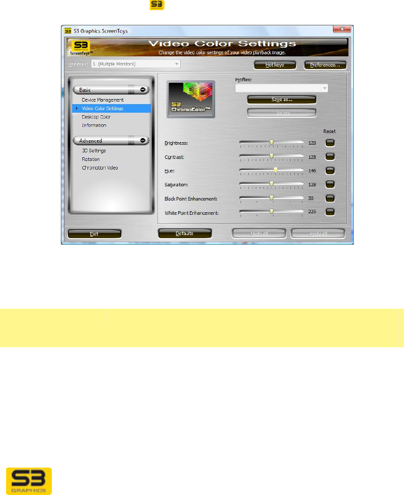
9.3 S3 ScreenToys Video Color Settings
With S3 ScreenToys Video Color Settings you can adjust the brightness,
contrast, hue and saturation of the display of video. S3 ScreenToys Video Color
Settings include ChromoColor™ support using the front-end pixel shader for
these adjustments.
ACCESS: To adjust video settings, right click on the desktop and click from the
menu to select S3 ScreenToys. From the left panel Basic menu, select Video
Color Settings. This utility is also accessible from the CHROME® menu
available on right-click of the taskbar icon menu.
OPTIONS: S3 ScreenToys Video Color Settings for color adjustment of video
may include the following.
Upper area Video settings are applied to the video stream currently
being assisted by hardware and are applied
irrespectively of the Monitors setting.
Monitors:
droplist If only one display monitor is connected, this list will not
be selectable.
If two display monitors are connected, a dropdown
monitor list will be available for selection. Click the
arrow to the right of the Monitors: dropdown list to
show a menu of all connected display output devices
(monitors). Each display device is shown as "N. Display
device name", where N is a number starting from 1.
User Guide for Chrome 500 Series Graphics
SG195-A.1 10/20/2008
Page 99
Select the device whose video adjustments you wish to
configure. (You can test the selection by experimentally
moving a slider to detect which monitor is currently
configurable.)
ChromoColor
image This image shows a graphic. This is a non-functional
user interface element.
Profiles area Video Color Settings Profiles can be created at any time,
and saved for future re-use.
Profiles Click on the arrow to the right of the Profiles: dropdown
list which provides a menu of all Video Color Settings
schemes available for selection. Click on a profile to
select it.
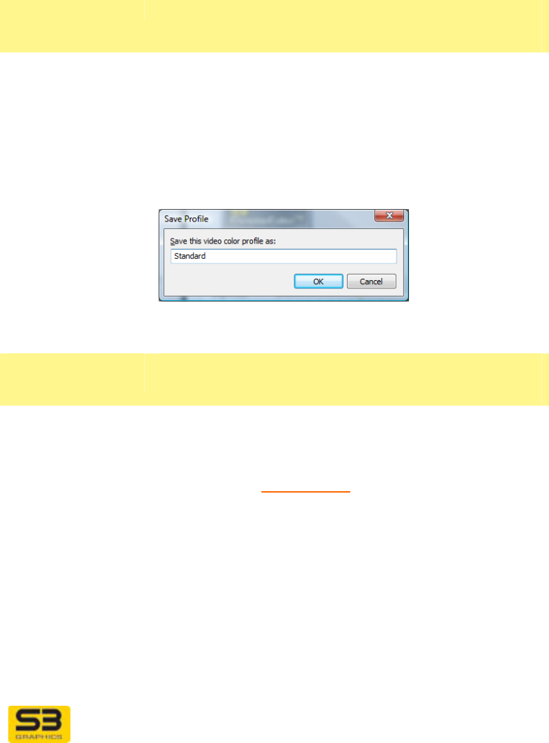
Save as… Click Save as… to save the current settings using the
existing profile name or a new name. Click OK to finish
your save.
Delete Click Delete to delete the currently selected profile.
Video Color
sliders area
Sliders Use the four slider bars in Video Color Settings to
change brightness, contrast, hue and saturation.
Refer to the S3 ScreenToys Basics for general
instructions on using a slider.
Brightness slider Drag the slider thumb along the bar to the right to
increase the luminance or amount of light in the display
output. Drag the slider bar to the left to decrease the
brightness and darken the display output.
Contrast slider Drag the slider thumb along the bar to the right to
increase the level of difference between the light and
dark areas of the display output. Drag the slider bar to
the left decrease the amount of contrast in the display
output.
User Guide for Chrome 500 Series Graphics
SG195-A.1 10/20/2008
Page 100
Hue slider Drag the slider thumb along the bar to the right to adjust
the hue of the display output towards purple. Drag the
slider bar to the left to make the hue greener.
Saturation slider Drag the slider thumb along the bar to the right to
increase the intensity of the colors in the display output.
Drag the slider thumb along the bar to the left to
decrease the color intensity of the display output.
Reset Click the Reset button to the right of each slider to return
the corresponding setting to the default.
Tonal
Adjustments
Use the Tonal Adjustments sliders to set threshold levels
which will change the dynamic ranges for shadows
(darks) and highlights (lights) in a video image.
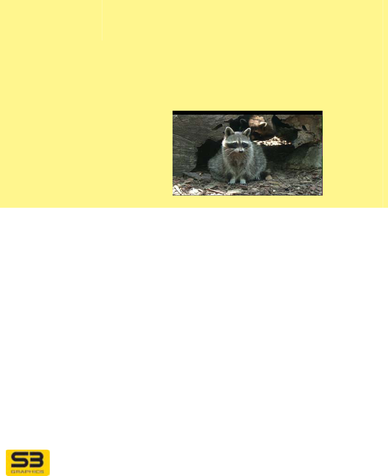
The images below show the types of changes in gray
scale that can be applied to the highlight and shadow
areas of an image by manipulating the Tonal
Adjustments slider thumbs. For reference, the original
image is:
Black Point
Enhancement
slider
The Black Point Enhancement control allows you to
adjust the range of black values which are displayed in
the shadow areas of the whole image. The adjustment
lets you expand the value range to make the darks in the
image appear more intense (deeper darks) or clip the
range to make the shadows lighter (brighter and lower
contrast).
Move the Black Point Enhancement slider thumb along
the bar to the left to decrease the Black Point
Enhancement threshold. This will decrease the
darkness of the shadows and thus lighten the shadows
in the image.
Move the Black Point Enhancement slider thumb along
the bar to the right to increase the Black Point
Enhancement threshold. This will increase the darkness
of the shadows and thus deepen the shadows in the
image. In the example below the Black Point threshold

User Guide for Chrome 500 Series Graphics
SG195-A.1 10/20/2008
Page 101
value has been increased, and the overall image
shadows appear darker.
Original:
Black Point Threshold increased:
White Point
Enhancement
slider
The White Point Enhancement control allows you to
adjust the range of white values which are displayed in
the highlight areas of the image. The adjustment lets you
expand the value range to make the whites in the image
appear either more intense (whiter whites) or clip the
value range to make the highlights darker (darker with
lower contrast).
Move the White Point Enhancement slider thumb along
the bar to the left to decrease the White Point
Enhancement threshold. This will decrease the
brightness of the highlights and thus darken the
highlights in the image.
Move the White Point Enhancement slider thumb along
the bar to the right to increase the White Point
Enhancement threshold. This will increase the
brightness of the highlights in the image. In the example
below the White Point threshold value has been
increased, and the overall image appears lighter.
Original:
White Point Threshold increased:
User Guide for Chrome 500 Series Graphics
SG195-A.1 10/20/2008
Page 102
9.4 S3 ScreenToys ChromoVision for HDMI
ACCESS: To enable ChromoVision capabilities for your HDMI device, visit the
Advanced/Options settings page accessible from the S3 ScreenToys Device
Management window. In the Display Devices area, click the HDMI icon. Next
check the Device Status checkbox underneath the icon. In the lower device
settings area, click the Advanced button. Locate the ChromoVision checkbox.
ChromoVision
options ChromoVision configuration options are usually available
for selection through the Options window.
Use ChromoVision
to display full-
screen video
Click the Use ChromoVision to display full-screen
video checkbox to enable ChromoVision.
When you are using Windows Vista or Windows XP,
ChromoVision allows full screen playback on your digital
HD device, while windowed video plays on another
display device associated with the Primary View. When
enabled, you can move and resize a video window on
your primary DVI or CRT device, and full screen video
will continue on your secondary HDMI, device.
You must be in Clone mode. ChromoVision is not
available when there is only one display output device,
and is not available when you Extend the desktop.
ChromoVision
Modes (for wide
screen devices)
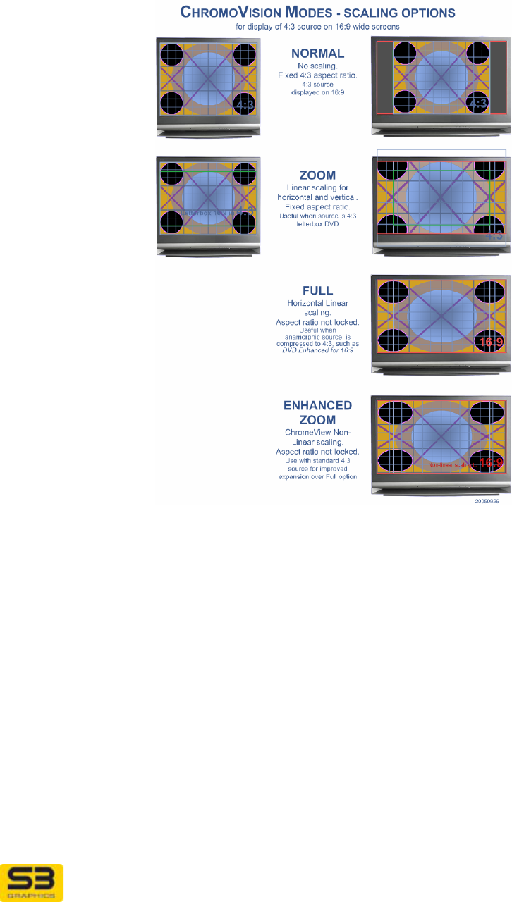
When ChromoVision is enabled (the ChromoVision
(full-screen video) check box is selected) and the
native aspect ratio of your display device is 16:9, then
the ChromoVision Modes options may be available for
optimizing viewing of 4:3 source content on your wide-
screen 16:9 display device.
These modes will not appear if you are not in Clone
mode or if your HDMI display device does not have a
native 16:9 aspect ratio.

User Guide for Chrome 500 Series Graphics
SG195-A.1 10/20/2008
Page 103
Normal Select Normal to display 4:3 source on 16:9 wide
screen with no scaling and no change to aspect ratio.
With Normal view, vertical black bars will appear on
both sides of the 4:3 image to fill the unused areas of
the wide screen.
Zoom Select Zoom to display letterboxed 4:3 source which
would otherwise show black bars all around the wide
screen image (such as a 4:3 letterbox DVD). Zoom
uses equal amounts of horizontal and vertical linear
scaling to expand the image to fill the wide screen 16:9
area. There is no change to the aspect ratio.
Full Select Full to display source material that has been
horizontally compressed during encoding, such as
anamorphic DVDs that are enhanced for 16:9. Full uses
linear scaling to horizontally and vertically stretch the 4:3
source to fit the 16:9 wide screen. This option changes
the aspect ratio.
Enhanced zoom
(ChromeView) Select Enhanced zoom to display standard 4:3 source
material that has not been horizontally compressed
during encoding. Enhanced zoom uses S3 Graphics’
customized ChromeView non-linear scaling algorithms to
provide optimal horizontal expansion of standard 4:3
source onto the 16:9 wide screen. ChromeView
Enhanced zoom is designed to provide less expansion
in the central image area where viewers usually focus
their attention. This option changes the aspect ratio.
User Guide for Chrome 500 Series Graphics
SG195-A.1 10/20/2008
Page 104
User Guide for Chrome 500 Series Graphics
SG195-A.1 10/20/2008
Page 105
9.5 S3 ScreenToys Chromotion Video
S3 Graphics’ hardware support for video acceleration is optimized for
compatibility with DirectX Video Acceleration (DXVA). The Chromotion Video
Engine provides IDCT support and post-processing capabilities for de-interlacing,
subpicture blending, video scaling, rotation, color conversion and video effects.
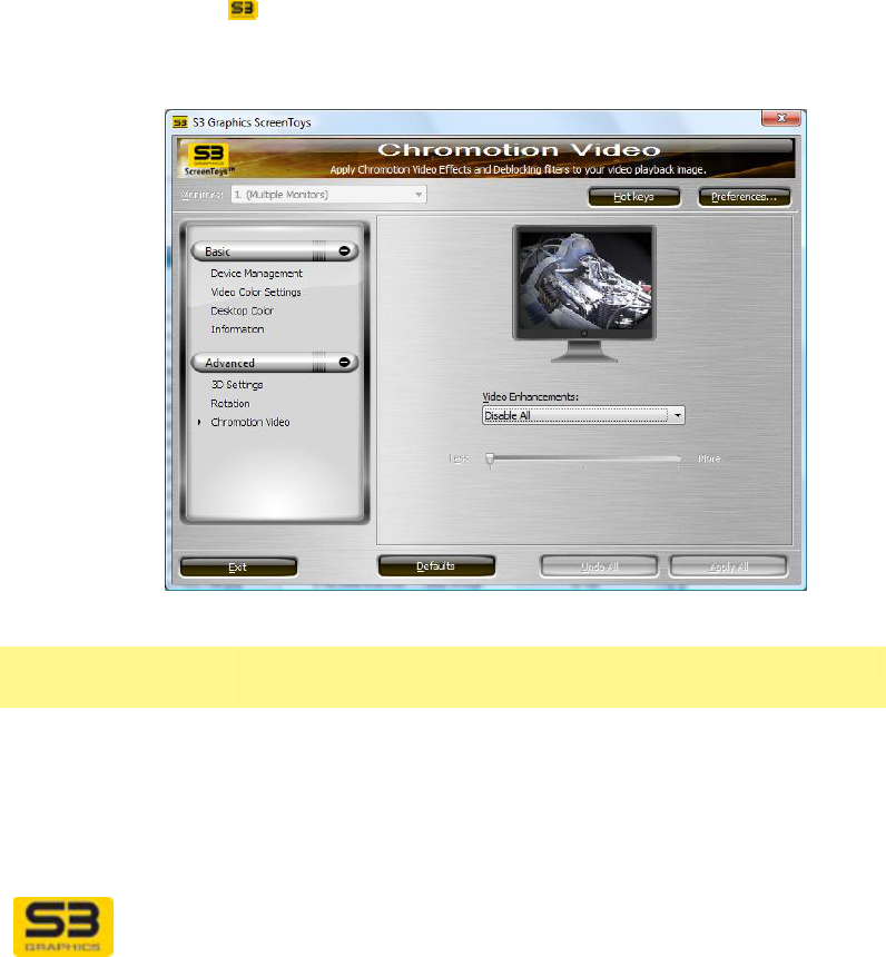
S3 ScreenToys Chromotion Video settings window allows you to apply real
time Chromotion Video Effects or Chromotion Video Deblocking to video images
playing on your desktop.
ACCESS: To use S3 ScreenToys Chromotion Video, right click on any
unpopulated area of the Desktop. Click S3 ScreenToys. From the Advanced
dropdown list menu in the left panel, click Chromotion Video. S3 ScreenToys
Chromotion Video is also accessible from the CHROME® menu available on
right-click of the S3 taskbar icon. Once the S3 ScreenToys Chromotion
Video settings window appears, the Chromotion Video effects and deblocking
filters will be available for configuration.
OPTIONS: S3 ScreenToys Chromotion Video settings options are:
Upper area
Effects monitor
image This "monitor" image shows a graphic preview image of
the artistic effects settings currently selected.
These are static images and change with the effect
option but do not reflect all changes in slider steppings.

User Guide for Chrome 500 Series Graphics
SG195-A.1 10/20/2008
Page 106
Effect/Filter
dropdown list Select an effect or filter from this dropdown list. Then
use the slider to set a value for the amount of visual
effect to be used during display of any video playback.
A slider bar allows you to adjust the amount or intensity
of the effect.
The slider thumb can be moved to the right to increase
(More) or the left to decrease (Less) the amount of the
effect. Each filter may have a different number of
allowed steps between left (Less) and right (More).
Disable All Click Disable All to remove any Deblocking filters or
Artistic License effects currently applied. The slider bar
is unavailable.
Emboss Click Emboss to produce output where most of the
image is displayed in (gray) tonal values. Edges retain
their original color. This makes the image resemble an
engraved stone relief image. (three step)
Neon Edges Click Neon Edges to produce a high-contrast image,
similar in effect to that of solarization in a photographic
print. Most of the image will have a very dark value (low
brightness) except for the edges between areas. The
edges are expressed as bands of bright, neon-like
colors. (three step)
Soft Focus Click Soft Focus to produce output where sharp edges
are removed to blur the image and produce a hazy
effect. Soft focus is also sometimes referred to as
Gaussian blur. This effect is often used by
photographers to soften facial details in portraiture.
(two step)
Sharpen Click Sharpen to produce output where the edges of
objects appear crisper. This is accomplished through
manipulation of the differences in contrast level between
the edge components. (multiple stepping)

User Guide for Chrome 500 Series Graphics
SG195-A.1 10/20/2008
Page 107
Complex Picture
Smoothing
Click Complex Picture Smoothing to use offset
deblocking which affects both the block boundaries and
the inside of the block. Use this method for flat images.
Complex Picture Smoothing should resolve image
artifacts propagated from the previous frame.
Move the slider thumb along the bar to the right to
increase the amount of the applied effect. (seven step).
User Guide for Chrome 500 Series Graphics
SG195-A.1 10/20/2008
Page 108
SECTION 10 TOOLS FOR THE 3D ENTHUSIAST
Use the S3 ScreenToys 3D settings configuration tool to configure or toggle
3D-related and capabilities to compensate for differences in the requirements
and behaviors of various Direct3D and OpenGL applications.
All 3D configuration page views include the following components:
Upper area
Monitor image This "monitor" image shows a graphic image. This is a
non-functional user interface element.
API logo or
image Displays the 3D API or option currently configurable.
3D Interface
By selecting from the 3D Interface list, you can specify
which set of available 3D configurations options you
wish to select. Current sets include:
Direct3D Select Direct3D to configure adjustments related to
Microsoft’s Direct3D API.
OpenGL Select OpenGL to configure adjustments related to the
OpenGL API for 3D graphics.
User Guide for Chrome 500 Series Graphics
SG195-A.1 10/20/2008
Page 109
10.1 S3 ScreenToys 3D settings for Direct3D
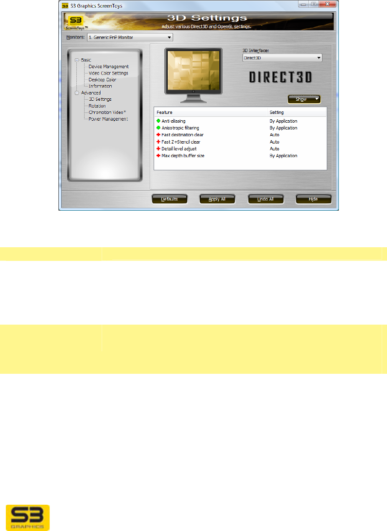
Use the S3 ScreenToys 3D settings page with the 3D Interface option set to
Direct3D to configure or toggle Direct3D-related capabilities to compensate for
differences in the requirements and behaviors of various Direct3D applications.
ACCESS: To adjust 3D settings for Direct3D, right click on the desktop and
select S3 ScreenToys from the menu. From the Advanced dropdown list menu
in the left panel, select 3D settings. This utility is also accessible from the
CHROME® menu available on right-click of the S3 taskbar icon. Once the S3
ScreenToys 3D settings window appears, select Direct3D from the 3D
Interface list and options for Direct3D configuration will be available.
Note: After you have completed your changes, please close and reopen your 3D
application. Different applications behave differently and some feature settings
may be initialized by the application on at launch time.
OPTIONS:
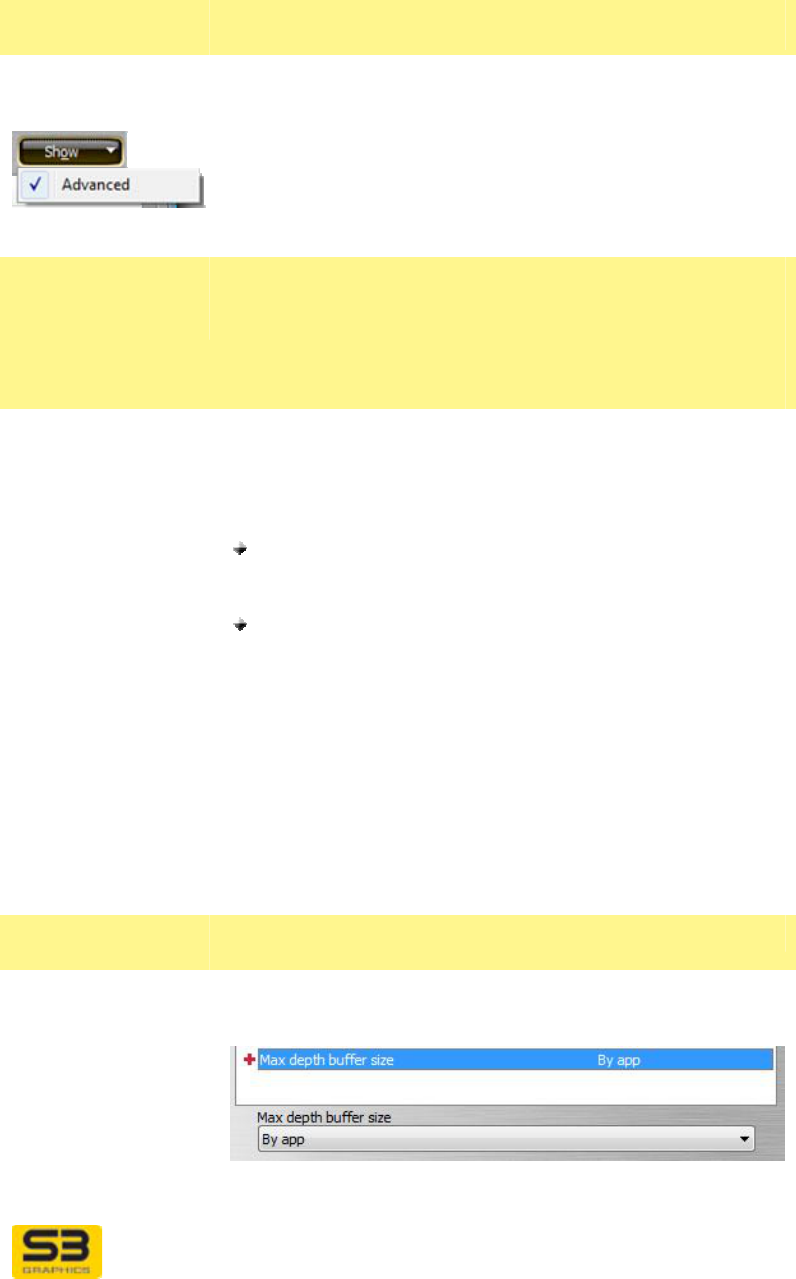
S3 ScreenToys 3D settings options for Direct3D include:
Upper area
Monitor image This "monitor" image shows a graphic image. This is a
non-functional user interface element.
3D Interface Select Direct3D from the list of 3D APIs and options.
This makes the Direct3D adjustments configurable.
Direct 3D bitmap Displays the 3D API to which the adjustments
configurable on this utility page will be applied.
User Guide for Chrome 500 Series Graphics
SG195-A.1 10/20/2008
Page 110
Direct3D general
area
Options in this area allow you to restore default settings,
and to select an expertise level for option visibility.
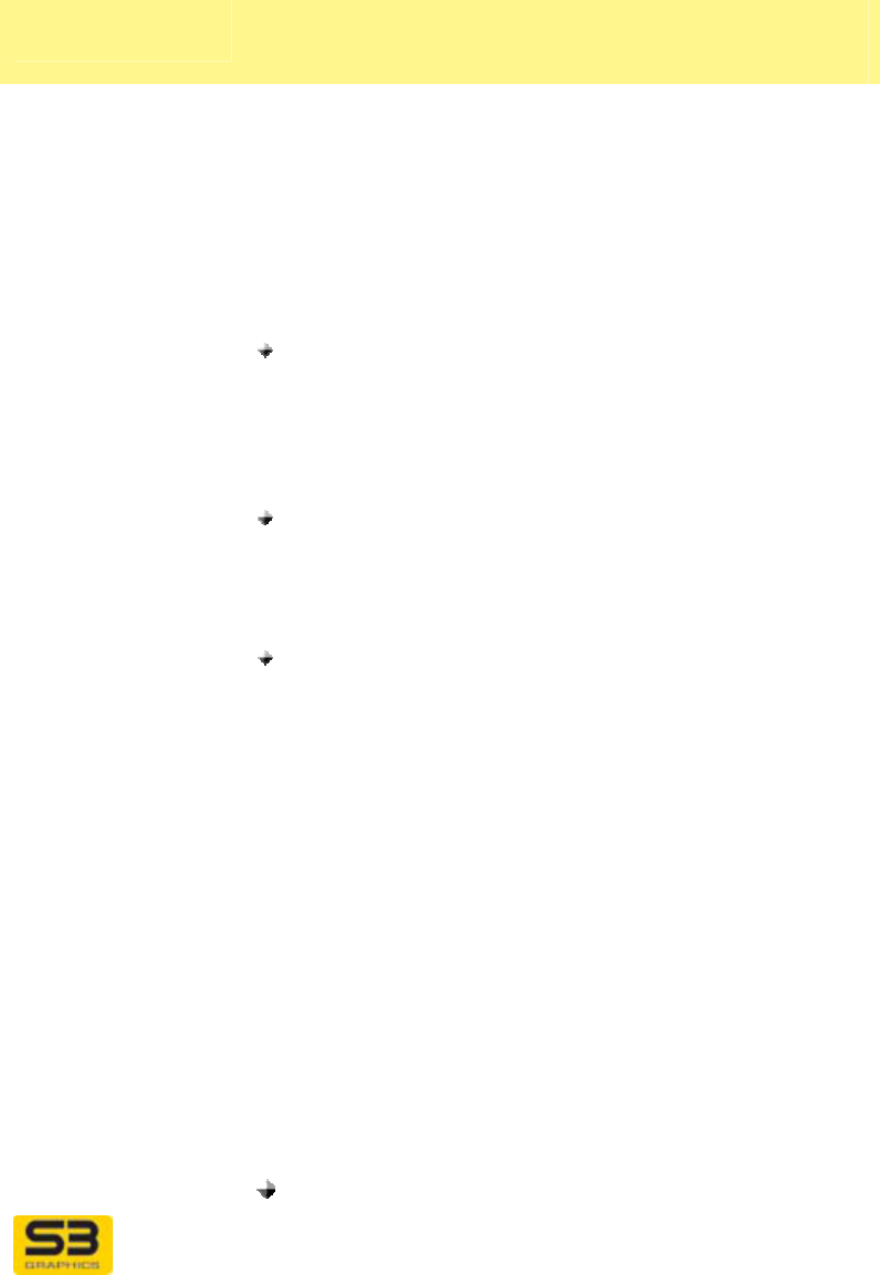
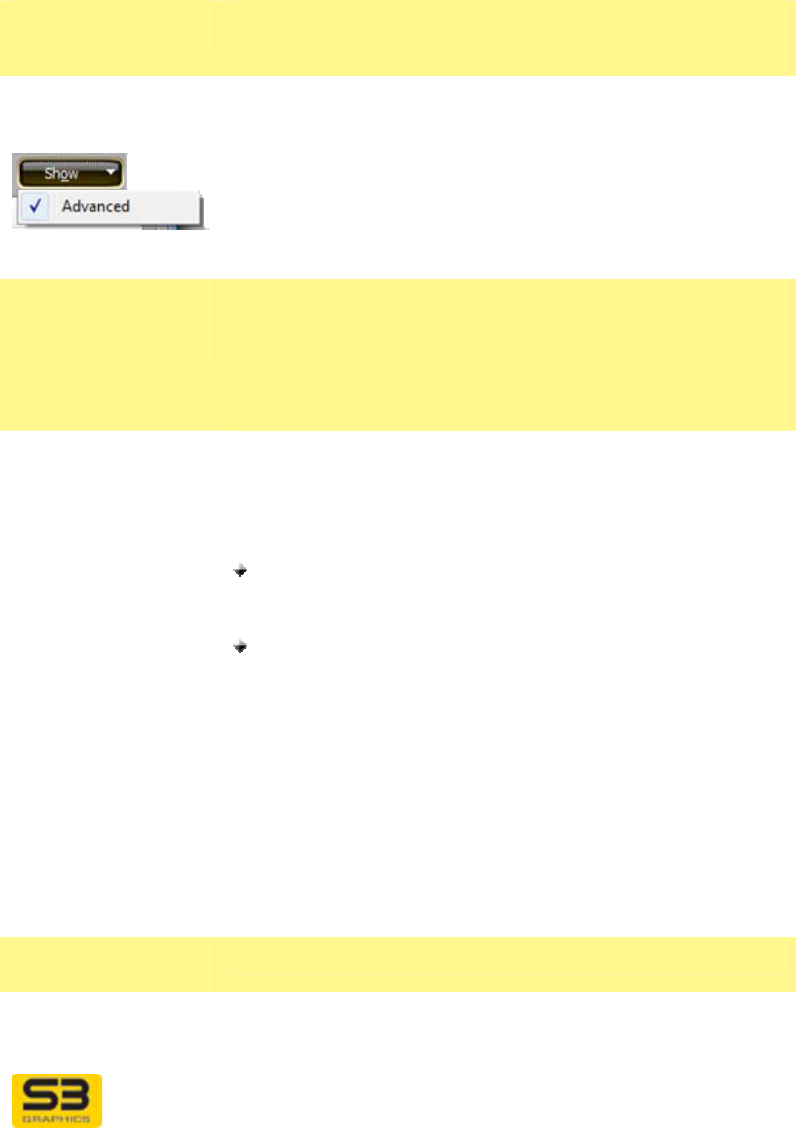
Show dropdown
button
Click Show button to display a dropdown list of user
expert levels. Click Advanced to display the settings
associated with these expert levels. When a check
precedes the Advanced level name in the Show menu,
that level’s features and settings will be listed as
available for adjustment through the Features and
Settings table on this utility page.
Feature and
Settings detail
area
Selected features and associated settings are saved
automatically and maintained by the driver. If a new
driver is installed, custom setting values must be re-
established. Settings are not affected by changes in
resolution, refresh or display output device changes.
Feature column The Feature list contains options available for
adjustment. The visible list can be expanded or reduced
using the Show button described above.
Feature Expert Levels include:
Standard settings are preceded by a green circular-
shaped icon zand are always available and cannot
be filtered from the Setting list.
Advanced settings are preceded by a red cross-
shaped icon + in the Settings Table. The red color
warns you that manipulating these settings should be
done with great care, as risk of creating an unstable
graphics environment increases when manipulating
these settings.
Setting column The Setting column reports the values you have
currently selected. These are not active values until after
you have clicked Apply to set your new parameters, and
re-launched your Direct3D application.
Setting
Adjustment area
Setting value
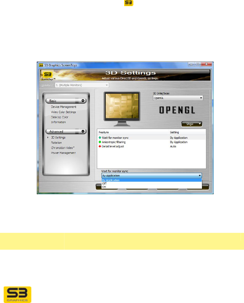
dropdown list When an item is highlighted in the Feature list, the area
below the Feature list will display the name of the
highlighted feature.
Click on the down arrow to the right of the dropdown
list to display a menu of available setting values that can
User Guide for Chrome 500 Series Graphics
SG195-A.1 10/20/2008
Page 111
be set for the selected feature. Click on your choice to
change a value. Your new value will appear in the
Setting column, but will not become the active value
until you click Apply and re-launch your Direct3D
application.
Features -
Standard
These Standard Features and associated settings are
available for adjustment.
Wait for monitor
sync Sometimes called Wait for Vsync, this feature option
controls whether or not buffer swaps and other activities
should be synchronized to the display’s Vertical
Synchronization or Vertical Retrace Signal and blanking
period, during which the display blanks as it retraces its
way from the bottom right to the upper left corner of the
screen.
Setting options include:
By App (default) – Select By App if you want the
Wait for monitor sync setting to change on
application requests. If Vsync OFF is requested, the
back buffer is flipped without waiting for vertical
retrace. If the application requests VSync ON, then
the back buffer is flipped while in vertical retrace.
ON – Select ON to always force a wait for monitor
sync. This option will reduce “tearing” artifacts.
Synchronizing with the vertical retrace constrains the
frame rate so that it does not exceed the refresh
rate.
OFF – Select OFF to allow buffer swaps to be
processed without waiting for vertical
synchronization. When a buffer flip occurs at a
different time than during the vertical blanking period,
visual artifacts, often described as “tearing” or
“shearing” may be apparent. Note that while visual
artifacts will probably occur with this setting, the
frame rate may increase.
Anti-aliasing Anti-aliasing is a technique to reduce jagged edges
(“jaggies”) of polygons and lines. Pixels on either side of
edges are sampled and then rendered as a blend of the
adjoining colors to smooth the appearance of the edge.
When anti-aliasing is enabled, images are less likely to
display “staircase” edges and broken lines. Sampling
results can be downscaled to the original size, producing
sub-samples of high quality.
Setting options include:
By App (default) – Select By App to allow the

User Guide for Chrome 500 Series Graphics
SG195-A.1 10/20/2008
Page 112
application to specify which level of super-sampling
should be applied. Otherwise, the driver selects an
optimized value. This is the default.
OFF – Select OFF to disable anti-aliasing. Image
quality usually suffers, but performance may
increase because less pixel processing occurs.
2X, 4X, 8X – Select a level to enable optimized
super-sampled anti-aliasing. This will provide
optimized anti-aliasing and still have only a minimal
impact on performance speed.
Anisotropic
filtering Anisotropic (which means non-uniform shape) filtering is
a filtering technique more advanced than trilinear and is
a technique which is useful for quadrilateral shaped and
angled areas of a texture image. A shaper image is
accomplished by interpolating and filtering multiple
samples from one or more MIP maps to better
approximate very distorted textures. Anisotropic can be
used in conjunction with bilinear or trilinear filtering as
well as MIP map filtering. While trilinear filtering is
capable of producing fine visuals, it only samples from a
square area, which is not the ideal sampling area for all
cases. Anisotropic filtering averages sixteen texture
samples, or taps, in a non-square, rectangular or
parallelogram shaped texture sampling pattern whose
length varies in proportion to the orientation of the
stretch effect. This sampling rate is four times the
sampling level of bilinear filtering and twice the sampling
level of trilinear filtering.
Textures applied to a sloped surface will not look fuzzy,
which is especially useful when rendering shapes with a
high degree of surface tilting in the X-Y-Z planes. Full
use of the anisotropic filtering capabilities may impact
performance.
Setting options include:
By App (default) – Select By App if you want S3
Graphics software to use the anisotropic filtering
level requested by the application. Not all
applications request anisotropic filtering, and S3
Graphics software does not perform anisotropic
filtering unless requested. This is the default.
OFF – Select OFF to force anisotropic filtering to be
always off.
2X – Select 2X to enable anisotropic filtering at its
lowest level. With this setting, 16 texture samples
(taps) selected from a non-square pattern will be
averaged to generate one texture element (texel)

User Guide for Chrome 500 Series Graphics
SG195-A.1 10/20/2008
Page 113
that is then applied to a single pixel.
3X,4X,…– Select intermediate sampling levels to
match your preferred balance between quality and
performance. The higher the sampling level, the
greater the degree of filtering. Visual quality will
improve at the expense of performance.
16X – Select 16X to force use of classic anisotropic
sampling using 128 taps in a non-square sampling
pattern. This level of filtering will produce very high
quality visual output, usually with a decrease in
rendering speed.
Features:
Advanced
Warning: Configuration of the following fetaures should
be done only by experienced users, as unexpected
behaviors or appearance may result.
Fast destination
clear Outputs from texture filtering and pixel shading activities
are sent to rendering target destination buffers. S3
Graphics hardware can quickly respond to a DirectX
application’s request to clear a destination buffer by
providing a hardware-assisted fast clear mechanism for
the clearing operation. Efficient clearing of the
destination buffers helps speed target rendering.
Setting options include:
Auto (default) – Select Auto if you want S3
Graphics software to own the decision whether it is
appropriate to use hardware assisted fast clear of
the destination buffer. Hardware assist is usually
enabled (ON).
ON – Select ON to force use of Fast Destination
Clear for optimum performance. All requests to clear
the destination buffer are done through hardware.
This will usually speed rendering, and is the
preferred setting. If an application has display issues
with the fast clear, then you may wish to disable this
feature to improve visual quality for that specific
application.
OFF – Select OFF to disable Fast Destination Clear.
Requests will use a traditional method and clear the
whole destination buffer. This will result in a slower
clearing cycle, but may resolve unexpected visual
quality issues.
Fast Z + Stencil
clear This option can be used to enable or disable the use of
S3 Graphics’ hardware-assisted fast clearing
mechanism for the Z and Stencil buffers.
The Z buffer is an area of video memory which stores a

User Guide for Chrome 500 Series Graphics
SG195-A.1 10/20/2008
Page 114
3D object’s value on the Z (depth) axis. S3 Graphics
software decides whether to make certain components
of an image visible or hidden to the viewer, based on
values in the Z-buffer.
The stencil buffer holds additional information for each
pixel about whether or not to draw it. Stencils can be of
any shape and can be thought of as a mask with cutouts
that allow an image to be seen through the cutout.
Stenciling is particularly useful in creating special
volumetric effects such as shadow volumes from
multiple light sources. The stencil buffer must interact
closely with the Z buffer.
Hardware assist speeds the clearing of the Z and Stencil
buffers for more efficient rendering.
Setting options include:
Auto (default) – Select Auto to allow S3 Graphics
software to own the decision whether it is
appropriate to use hardware assisted fast clearing of
the Z and/or Stencil buffers. Usually Fast Z clear is
enabled (ON).
ON – Select ON to force Fast Z clear to always ON,
so that all requests to clear the Z and Stencil buffers
will always be processed through hardware. This will
usually speed rendering, and is the preferred setting.
OFF – Select OFF to disable hardware Fast Z clear
and to force clearing of the Z and Stencil buffers
using traditional methods. This will result in a slower
clearing cycle, but may resolve unexpected visual
quality issues. If you suspect an application has
quality issues with Fast Clear, then you may try
disabling this feature to see if it improves visual
quality for that specific application.
Detail level adjust The number of levels or steps available for use between
the largest and the smallest MIP map image can be
specified by applications and driver software. Called the
MIP map Level of Detail (LOD) bias, settings are
selectable and can produce results ranging from high
speed performance to high visual quality.
“MIP mapping” is actually an abbreviation for the Latin
phrase Multum im Parvum, which means “many in less.”
MIP mapping textures will increase quality and detail by
generating and storing scaled versions of a texture
image. When the texture is rendered in a 3D scene, MIP

User Guide for Chrome 500 Series Graphics
SG195-A.1 10/20/2008
Page 115
map levels computed by trilinear texturing are available
for use by the Direct3D application.
High quality images will be sharper and more aliased
and will result from the use of a higher number of MIP
map levels. Blurrier images result from using a smaller
number of intermediary MIP map levels. Because less
texture data is used, higher performance is associated
with fewer MIP map levels.
Setting options include:
Auto (default) – Select Auto to let S3 Graphics
software provide optimized control of adjustments for
Level of Detail bias.
0 (Quality) – Select 0 (Quality) to use the highest
available visual quality, using the maximum Level of
Detail bias. This number tells S3 Graphics software
to use the highest number of MIP map levels
possible. This setting will produce the greatest level
of visual quality and detail, but will often have a
significant impact on rendering speed, as much
texture data is processed.
1, 2, 3, 4, 5, 6, 7…– Select any intermediate level to
achieve your optimal balance between quality and
performance.
8 (Performance) – Select 8 (Performance) to tell S3
Graphics software to use the smallest number of MIP
map levels available. This setting will produce higher
speed performance at the expense of visual quality.
Max depth buffer
size Use this setting to control the maximum precision
available for the Depth Buffer (Z buffer). Visual quality
increases with the greater precision available when
using higher bit buffers. There may be a slight
corresponding decrease in rendering speed.
Setting options include:
By App (default) – Select By App if you want S3
Graphics software to provide the depth buffer size
requested by the application. This is the default.
16-bit – Select 16 for force a 16 bit depth buffer.
Applications may request a 16 bit depth buffer. This
depth will provide the fastest rendering speed.
Because this is the least precise format, it has the
potential for decreased visual quality, especially by
creating surface artifacts in distant objects.
24-bit – Select 24 to force a 24 bit depth buffer,
which would be a buffer with single precision floating

User Guide for Chrome 500 Series Graphics
SG195-A.1 10/20/2008
Page 116
point without a low byte for the mantissa.
32-bit – Select 32 to force a 32 bit depth buffer. The
32 bit depth buffer will provide the greatest level of
precision possible, using a standard single precision
floating point format. While this buffer precision will
provide high visual quality, rendering speed will be
slower.
Note: Forcing a buffer depth may produce noticeable
artifacts. For example, if precision is degraded by
substituting a 16 bit depth buffer, artifacts would be
visible in the resulting images.
User Guide for Chrome 500 Series Graphics
SG195-A.1 10/20/2008
Page 117
10.2 S3 ScreenToys 3D Settings for OpenGL
Use the S3 ScreenToys 3D Settings page with the 3D Interface dropdown list
set to OpenGL to configure or toggle OpenGL-related capabilities to compensate
for differences in the requirements and behaviors of various OpenGL
applications.
ACCESS: To adjust OpenGL configuration settings, right click on the desktop
and select S3 ScreenToys from the menu. In the Advanced dropdown list in the
left panel, click 3D settings. This utility is also accessible from the CHROME®
menu accessible on right-click of the S3 taskbar icon. Once the S3
ScreenToys 3D settings window appears, from the 3D Interface list, select
OpenGL and feature options for OpenGL configuration will be available.
Note: After you have completed your changes, please close and reopen your 3D
application. Different applications behave differently and some feature settings
may be initialized by the application on at launch time.
OPTIONS:
S3 ScreenToys 3D settings for OpenGL include:
Upper area
Monitor image This "monitor" image shows a graphic image. This is a
non-functional user interface element.
3D Interface Select OpenGL from the dropdown list of 3D APIs and
User Guide for Chrome 500 Series Graphics
SG195-A.1 10/20/2008
Page 118
options. This makes the OpenGL adjustments
configurable.
OpenGL Displays the 3D API to which the adjustments
configurable on this utility page will be applied.
OpenGL general
area
Options in this area allow you to restore default settings,
and to select an expertise level for option visibility.
Show dropdown
button
Click Show button to display a dropdown list of user
expert levels. Click Advanced to display the settings
associated with these expert levels. When a check
precedes the Advanced level name in the Show menu,
that level’s features and settings will be listed as
available for adjustment through the Features and
Settings table on this utility page.
Feature and
Settings detail
area
Selected features and associated settings are saved
automatically and maintained by the driver. If a new
driver is installed, custom setting values must be re-
established. Settings are not affected by changes in
resolution, refresh or display output device changes.
Feature column The Feature list contains options available for
adjustment. The visible list can be expanded or reduced
using the Show button described above.
Feature Expert Levels include:
Standard settings are preceded by a green circular-
shaped icon zand are always available and cannot
be filtered from the Setting list.
Advanced settings are preceded by a red cross-
shaped icon + in the Settings Table. The red color
warns you that manipulating these settings should be
done with great care, as risk of creating an unstable
graphics environment increases when manipulating
these settings.
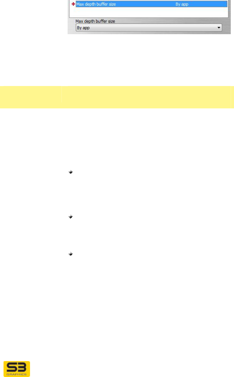
Setting column The Setting column reports the values you have
currently selected. These are not active values until after
you have clicked Apply to set your new parameters, and
re-launched your Direct3D application.
Setting
Adjustment area
Setting value
dropdown list When an item is highlighted in the Feature list, the area
below the Feature list will display the name of the
highlighted feature.
User Guide for Chrome 500 Series Graphics
SG195-A.1 10/20/2008
Page 119
Click on the down arrow to the right of the dropdown
list to display a menu of available setting values that can
be set for the selected feature. Click on your choice to
change a value. Your new value will appear in the
Setting column, but will not become the active value
until you click Apply and re-launch your Direct3D
application.
Features -
Standard
These Standard Features and associated settings are
available for adjustment.
Wait for monitor
sync Sometimes called Wait for Vsync, this option controls
whether or not buffer swaps and other activities should
be synchronized to the display’s Vertical Synchronization
or Vertical Retrace Signal and blanking period, during
which the display blanks as it retraces its way from the
bottom right to the upper left corner of the screen.
Setting options include:
By App (default) – Select By App if you want the
Wait for monitor sync setting to change on
application requests. If Vsync OFF is requested, the
back buffer is flipped without waiting for vertical
retrace. If the application requests VSync ON, then
the back buffer is flipped while in vertical retrace.
ON – Select ON to always force a wait for monitor
sync. This option will reduce “tearing” artifacts.
Synchronizing with the vertical retrace constrains the
frame rate so that it does not exceed the refresh
rate.
OFF – Select OFF to allow buffer swaps to be
processed without waiting for vertical
synchronization. When a buffer flip occurs at a
different time than during the vertical blanking period,
visual artifacts, often described as “tearing” or
“shearing” may be apparent. Note that while visual
artifacts will probably occur with this setting, the
frame rate may increase.
Anisotropic
filtering Anisotropic (which means non-uniform shape) filtering is
a filtering technique more advanced than trilinear, which
is useful for quadrilateral shaped and angled areas of a
texture image. A shaper image is accomplished by
interpolating and filtering multiple samples from one or

User Guide for Chrome 500 Series Graphics
SG195-A.1 10/20/2008
Page 120
more MIP maps to better approximate very distorted
textures. Anisotropic can be used in conjunction with
bilinear or trilinear filtering as well as MIP map filtering.
While trilinear filtering is capable of producing fine
visuals, it only samples from a square area, which is not
the ideal sampling area for all cases. Anisotropic filtering
averages sixteen texture samples, or taps, in a non-
square, rectangular or parallelogram shaped texture
sampling pattern whose length varies in proportion to the
orientation of the stretch effect. This sampling rate is four
times the sampling level of bilinear filtering and twice the
sampling level of trilinear filtering.
Textures applied to a sloped surface will not look fuzzy,
which is especially useful when rendering shapes with a
high degree of surface tilting in the X-Y-Z planes. Full
use of the anisotropic filtering capabilities may impact
performance.
Setting options include:
By App (default) – Select By App if you want S3
Graphics software to use the anisotropic filtering
level requested by the application. Not all
applications request anisotropic filtering, and S3
Graphics software does not perform anisotropic
filtering unless requested. This is the default.
OFF – Select OFF to force anisotropic filtering to be
always off.
2X – Select 2X to enable anisotropic filtering at its
lowest level. With this setting, 16 texture samples
(taps) selected from a non-square pattern will be
averaged to generate one texture element (texel)
that is then applied to a single pixel.
3X, 4X, …, 15X – Select intermediate sampling
levels to match your preferred balance between
quality and performance. The higher the sampling
level, the greater the degree of filtering. Visual
quality will improve at the expense of performance.
16X – Select 16X to force use of classic anisotropic
sampling using 128 taps in a non-square sampling
pattern. This level of filtering will produce very high
quality visual output, usually with a decrease in
rendering speed.

User Guide for Chrome 500 Series Graphics
SG195-A.1 10/20/2008
Page 121
Features:
Advanced
Warning: Configuration of the following features should
be done only by experienced users, as unexpected
behaviors or appearance may result.
Detail level adjust The number of levels or steps available for use between
the largest and the smallest MIP map image can be
specified by applications and driver software. Called the
MIP map Level of Detail (LOD) bias, settings are
selectable and can produce results ranging from high
speed performance to high visual quality.
Also known as “MIP mapping” is actually an abbreviation
for the Latin phrase Multum im Parvum, which means
“many in few.” MIP mapping textures increases quality
and detail by generating and storing scaled versions of a
texture image. When the texture is rendered in a 3D
scene, MIP map levels computed by trilinear texturing
are available for use by the OpenGL application.
High quality images will be sharper and more aliased
and will result from the use of a higher number of MIP
map levels. Blurrier images result from using a smaller
number of intermediary MIP map levels. Because less
texture data is used, higher performance is associated
with fewer MIP map levels.
Setting options include:
Auto (default) – Select Auto to let S3 Graphics
software provide optimized control of adjustments for
Level of Detail bias.
0 (Quality) – Select 0 (Quality) to use the highest
available visual quality, using the maximum Level of
Detail bias. This number tells S3 Graphics software
to use the highest number of MIP map levels
possible. This setting will produce the greatest level
of visual quality and detail, but will often have a
significant impact on rendering speed, as much
texture data is processed.
1, 2, 3, 4, 5, 6, 7…– Select any intermediate level to
achieve your optimal balance between quality and
performance.
8 (Performance) – Select 8 (Performance) to tell S3
Graphics software to use the smallest number of MIP
map levels available. This setting will produce higher
speed performance at the expense of visual quality.
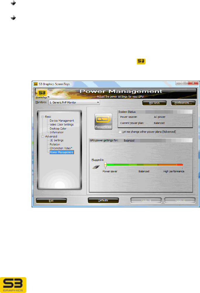
User Guide for Chrome 500 Series Graphics
SG195-A.1 10/20/2008
Page 122
SECTION 11 POWER MANAGEMENT CONTROLS
The S3 ScreenToys Power Management controls provide an aid for conserving
power on notebook (laptop) and other power-sensitive systems. It is available on
selected systems running Windows Vista and Windows XP.
11.1 S3 ScreenToys Power Management
S3 ScreenToys Power Management has two basic modes for controlling the
level of power conservation:
Automatic Power Conservation Mode (Default setting) which lets the
S3 Graphics software decide the optimal setting for you.
Manual Power Conservation Mode which allows you to use a slider bar
to change between settings that conserve power (but reduce speed) or
increase speed (but use more power).
ACCESS: If your configuration supports power management through S3
ScreenToys Power Management, a menu option will be available through the
CHROME menu accessible by right click on the taskbar icon, or from the
Advanced menu on the S3 ScreenToys window.
OPTIONS:
S3 ScreenToys Power Management options are applied globally, regardless of
display configuration. You cannot adjust settings unless you have selected the
Let me change other power plans (Advanced) checkbox.
User Guide for Chrome 500 Series Graphics
SG195-A.1 10/20/2008
Page 123
System Status This area shows the current graphics power
management status.
Power Source The power source may be reported as:
AC power
Battery, or
Unknown.
If the power source is not Battery, then the Battery and
hours remaining options are blank and disabled.
Battery remaining If the power source is Battery, then the battery life
remaining (as a percentage) is shown.
Hours remaining If the power source is Battery, then the time remaining
for the available battery power is shown. The time will be
shown in hours. If the operating system reports both
minutes and hours, then minutes will also be displayed.
Current Power
Plan This shows the currently selected Power Plan.
See below for detail description of the available power
plans.
Let me change… Click the checkbox Let me change other power plans
(Advanced) to disable the Automatic (default) power
setting and enable Manual power setting.
If power management options are not configurable on
this system, this option will be dimmed and not available.
Uncheck this option to use the default Automatic settings
optimized for your system. When this option is
unchecked or when it is dimmed and not available, the
slider is not available for adjustment. S3 Graphics
software will automatically:
provide maximum speed when the graphics engines
are active,
or
conserve power when engines are idle.
If your system supports automatic power management,
and you have not previously manually specified a
preferred S3 ScreenToys Power management power
savings setting, automatic power management will be
enabled by default.
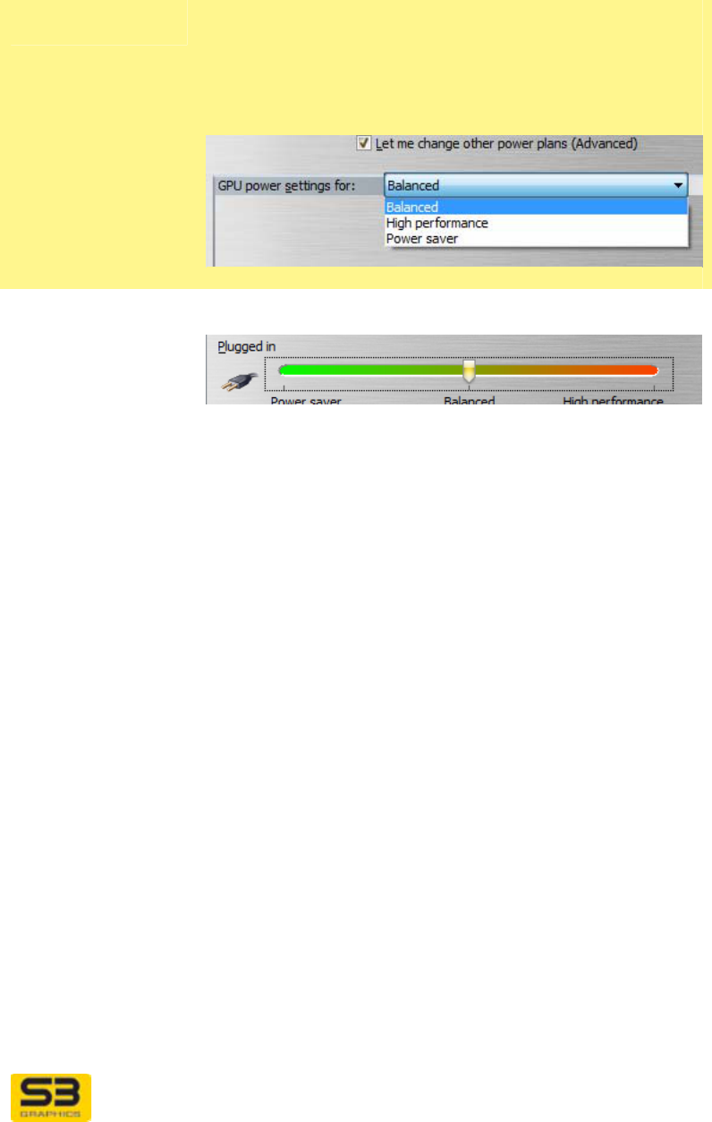
User Guide for Chrome 500 Series Graphics
SG195-A.1 10/20/2008
Page 124
GPU Power
Settings area When the Let me change… checkbox is checked, you
are in Advanced manual mode and the slider bar will
be available to adjust and change power settings.
A dropdown list will appear along the area’s title bar,
which will contain a menu of the available power options.
Power source
bitmap A bitmap to the left of the slider bar represents the
current power source.
Power setting
slider (Advanced
manual mode)
In Advanced Manual Power Management Mode, the
slider bar is available and allows you to manually change
conservation levels. One end of the slider bar is
associated with high power conservation and the other
end of the slider scale is associated with high
performance/speed.
Move the slider bar to the left towards the green Power
Saver (left) side to conserve power (reduces speed).
Move the slider bar to the right towards the red High
Performance (right) side to increase performance and
speed (and power consumption).
When you select a power setting via the slider bar and
apply it, S3 Graphics software will remember and restore
the specified power setting during normal operation and
at re-boot and resume. This setting is applied regardless
of your current power source (AC or battery).

User Guide for Chrome 500 Series Graphics
SG195-A.1 10/20/2008
Page 125
Power Plans Below are the power plans which may be available.
Power Saver
setting Use the Power Saver setting to reduce power
consumption. This setting will reduce speed and may
lower performance.
Balanced setting The Balanced setting provided the default setting
provided by the driver to provide an optimal balance
between power consumption and high performance.
High Performance
setting Increase the High Performance setting by moving the
slider bar to the right. Selecting maximum speed will
provide maximum speed, regardless of the current
power source.
When the power source is battery and you have selected
the maximum speed setting, you will have maximum
drain on the battery. This will significantly shorten the
time you will be able to run the system before the battery
needs recharging.
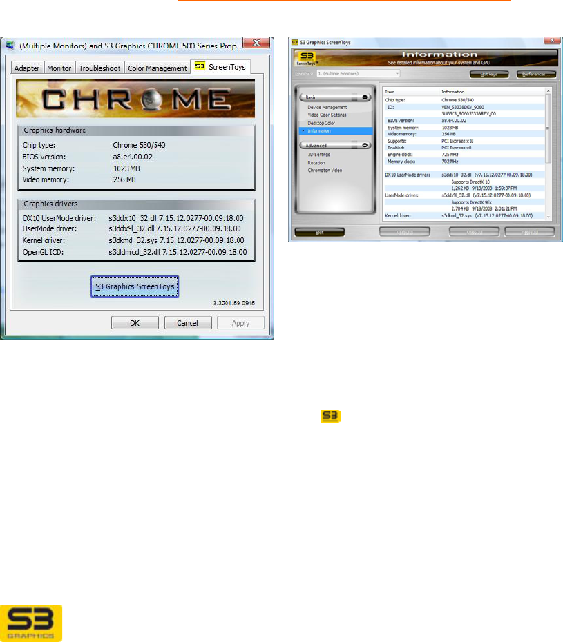
User Guide for Chrome 500 Series Graphics
SG195-A.1 10/20/2008
Page 126
SECTION 12 DISPLAY IDENTIFICATION & INFORMATION
Use S3 ScreenToys Information, Control Panel System tools or WinS3ID to
identify your Display Adapter. This information is useful when troubleshooting or
locating compatible driver updates.
12.1 S3 ScreenToys Information
S3 ScreenToys Information page and tab both tell you information about the S3
Graphics adapter and associated software. The S3 ScreenToys tab has been
discussed previously, see Display Settings Advanced S3 ScreenToys tab. The
Information page contains additional information.
ACCESS: To use the S3 ScreenToys Information page, right click on any
unpopulated area of the Desktop. Click S3 ScreenToys. From the left panel
Basic menu select Information. This utility is also accessible from the
CHROME® menu available on right-click of the taskbar icon menu. The
Information settings panel will now be available for viewing.
OPTIONS: The S3 ScreenToys Information page settings area includes the
following items which are also reported on the Display Settings Advanced S3
ScreenToys tab. Additional detail is provided, such as Memory Clock and Engine
Clock.
User Guide for Chrome 500 Series Graphics
SG195-A.1 10/20/2008
Page 127
System
Configuration
area
This area includes information related to the system and
BIOS configuration.
Chip type Shows the S3 Graphics chip type name.
ID string Shows the PCI Vendor ID, Device ID, Subsystem ID and
Subsystem Vendor ID for the graphics hardware.
BIOS version Shows the S3 Graphics video BIOS version.
System memory Shows the amount of detected system memory.
Video memory Shows the amount of detected video memory.
Bus information Shows the bus interface standard for this Hardware (for
example, PCI Express x16), and the current enabled
capability.
Engine clock
Memory clock Shows the graphics engine clock setting and the clock
setting for the graphics memory.
S3 Driver area This area includes information about the display drivers.
File data is provided, such as the file size and date/time.
(XP: names will be different)
DirectX 10
UserMode and
UserMode driver
Shows the S3 Graphics Windows Vista User Mode
display driver filename, version number and DirectX
level.
Driver version numbers are divided into two portions
separated by a hyphen. The first portion is the version
number following Microsoft’s conventional format. The
portion after the hyphen is S3 Graphics internal version
number.
Kernel driver Shows the S3 Graphics Windows Vista Kernel Mode
driver filename and version number.
OpenGL ICD Shows the S3 Graphics Installable Client Driver for
OpenGL filename and version number.
The following additional items are found on the S3 ScreenToys Information
settings area. (These are not found on the Display Settings Advanced S3
ScreenToys tab, but many may be found using system reporting tools provided
with the operating system, such as are accessible from Control Panel.)
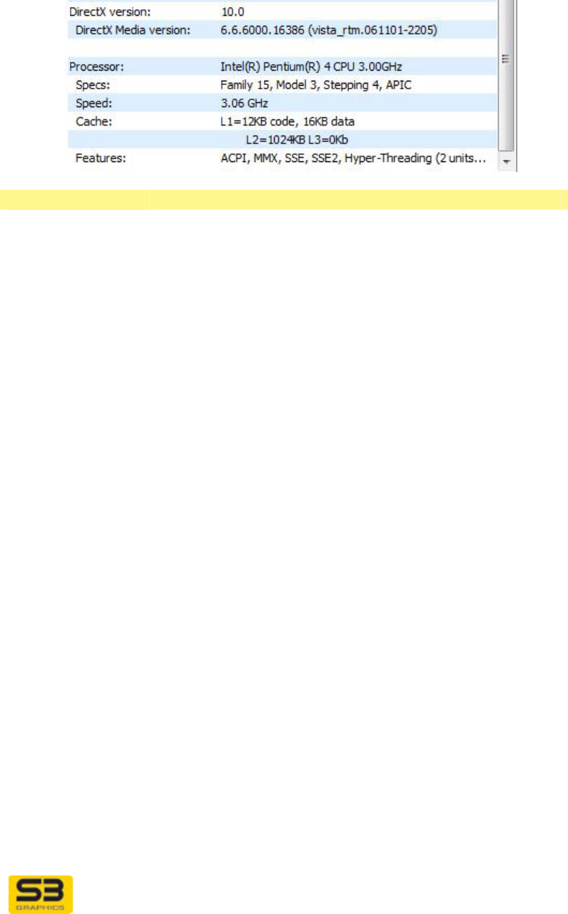
User Guide for Chrome 500 Series Graphics
SG195-A.1 10/20/2008
Page 128
Additional Info:
Direct X version Reports the version of Direct X installed in the system.
Direct X Media
version Display the current version number of the installed Direct
X Media files.
Processor
information These lines contain detailed information about the
system processor, including manufacturer, speed, cache
detail and key features.
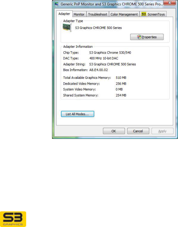
User Guide for Chrome 500 Series Graphics
SG195-A.1 10/20/2008
Page 129
12.2 Information from Control Panel System
To use Windows Vista or Windows XP Control Panel System information to
identify your graphics device:
• In Windows Vista, click Start. Right click on Computer, click Manage. In
the left panel, select Device Manager, or
• In Windows Vista, click Start, click System & Maintenance, then click
System. In the left panel Tasks list, select Device Manager, or
• In Windows XP, click Start, click Control Panel, double-click the System
icon. This opens the System Properties window. Click Hardware tab,
then click Device Manager button.
Click the plus sign in the box preceding Display adapters. Double-click S3
Graphics CHROME 500 Series (or specific product name). Information
regarding your adapter is now accessible through the General, Driver and
Resources tabs.
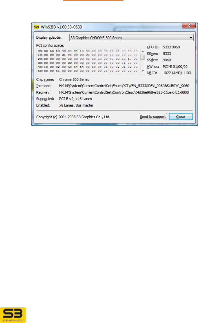
User Guide for Chrome 500 Series Graphics
SG195-A.1 10/20/2008
Page 130
12.3 WinS3ID for Chip Identification
WinS3ID is a Windows-compatible utility that you can run to identify the S3
Graphics product installed in your system, even when no S3 Graphics software
drivers are installed. This tool is not included in driver packages, but is available
for download from the www.s3graphics.com drivers download access page.

User Guide for Chrome 500 Series Graphics
SG195-A.1 10/20/2008
Page 131
SECTION 13 MAINTENANCE GUIDE
13.1 Finding Driver Updates
Periodic software updates may be issued by your vendor as new features or bug
fixes become available.
Places to check for driver updates available for installation with your hardware
might include:
Your OEM (Original Equipment Manufacturer) board vendor’s website. This is
often the only location where drivers customized for specific OEM hardware
are available.
Microsoft Windows Update is an online extension to Windows that delivers
driver updates to Windows XP, Windows Vista and related operating systems.
http://update.microsoft.com/microsoftupdate/v6/default.aspx?ln=en-us
To look specifically for updates compatible with your graphics board, follow
the on-screen directions to scan or review available drivers. Follow the online
directions to complete your update.
Your chipset adapter manufacturer’s website: www.s3graphics.com. S3
Graphics provides standard drivers which may not be customized to your
specific hardware.
13.2 Installing Driver Updates
Driver update packages from S3 Graphics include a compatible set of display
drivers and multi-language utility applets as well as an install tool for easy
installation.
A software driver update can be performed by running SETUP.EXE from the S3
Graphics software package. Rebooting the system ensures that you have fully
initialized the update.
Step 1. Copy a S3 Graphics Driver Update package that is compatible
with your hardware to a CD or to a folder on your hard disk. Driver
packages are often compressed. If you do not see SETUP, double
click on the executable file to expand the package prior to
installation.
Step 2. Click Start, Run, and Browse to the location of SETUP.EXE.
Click Open.
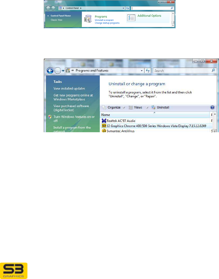
User Guide for Chrome 500 Series Graphics
SG195-A.1 10/20/2008
Page 132
Step 3. Follow the install tool’s direction. Steps for this install are similar to
those outlined for initial installation using your vendor supplied CD,
except that the hardware is already in use.
Step 4. Click Start, Shutdown, Restart to fully initialize your update.
13.3 Software Removal
Use one of the following procedures if you want to remove your S3 Graphics
software.
13.3.1 Software Removal with Vista Uninstall
Step 1. With Windows Vista: Click Start, then Control Panel.
Step 2. Click Programs/Uninstall a program to open the Uninstall or
change a program window.
Step 3. Scroll through the list of programs available for automatic removal
and click S3 Graphics CHROME 500 Series Windows Vista
Display follow by version number. Note: the Display driver title
may vary.
Step 4. Click Uninstall This launches the uninstall program for the S3
Graphics CHROME 500 Series Windows Vista Display.
Step 5. Follow the instructions. Once the wizard has finished, the driver
and utility removal will be complete only after a system restart.
Review the following step before selecting restart.
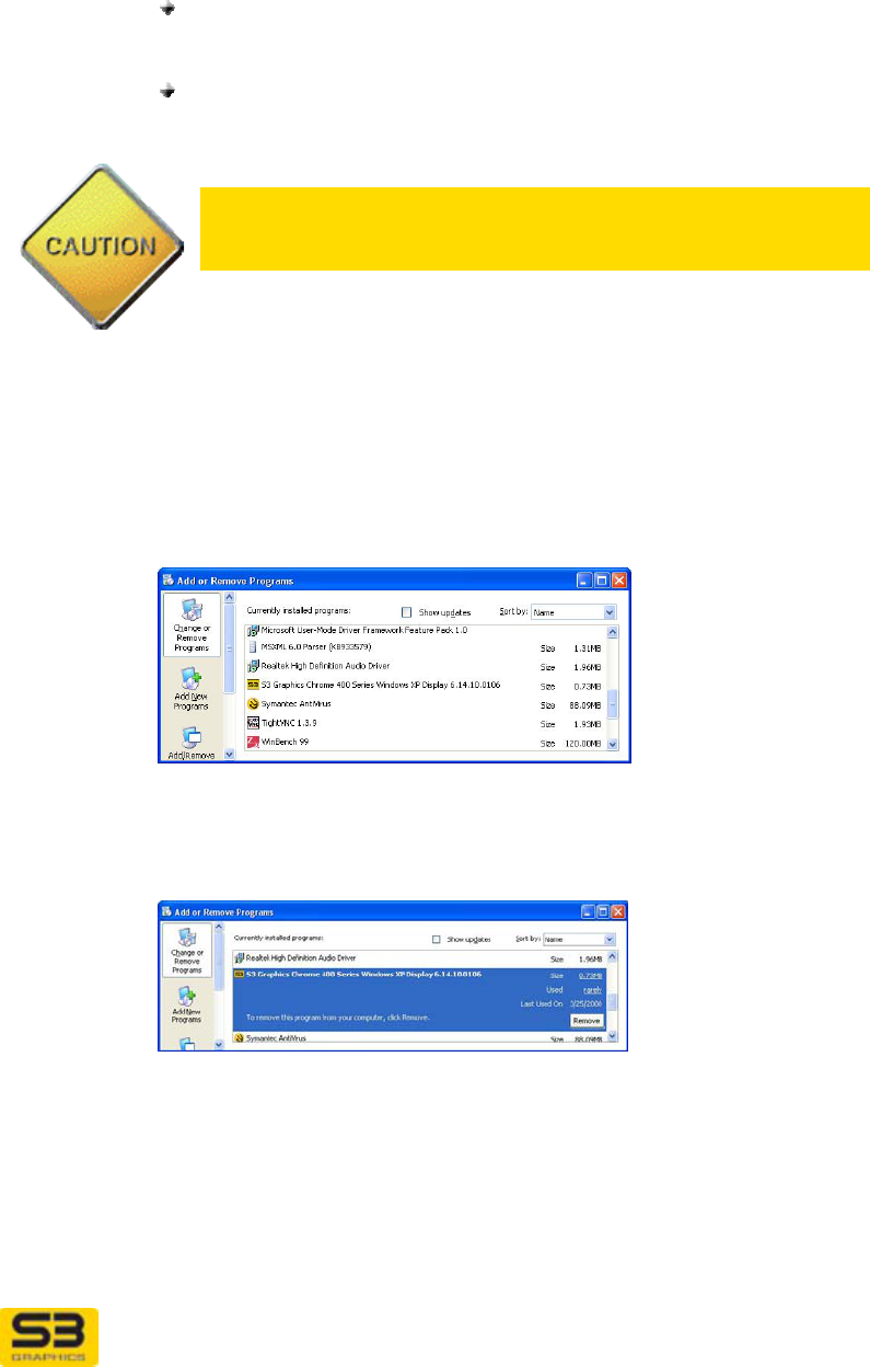
User Guide for Chrome 500 Series Graphics
SG195-A.1 10/20/2008
Page 133
Step 6. For the changes to take full effect, you must now reboot.
If you are going to physically remove your S3 Graphics
hardware: Click Start, Shutdown, Shutdown. Remove the
board from your system now before rebooting the computer.
If you will keep your current S3 Graphics hardware in the
computer: Click Start, Shutdown, Restart. Your computer will
restart.
Caution: Windows will not physically delete the S3Graphics
Driver and Utilities files. After reboot, Windows may be able to
identify your hardware and will try to reinstall the drivers.
13.3.2 Software Removal with XP Add/Remove Programs
Step 7. With Windows XP: Click Start, then Settings, Control Panel.
Step 8. Double-click Add or Remove Programs to open the Add or
Remove Programs window.
Step 9. Scroll through the list of programs available for automatic removal
and click S3 Graphics CHROME 500 Series Windows XP
Display follow by version number. Note: the Display driver title
may vary.
Step 10. Click Change/Remove. This launches the uninstall program for
the S3 Graphics CHROME 500 Series Windows XP Display.
Step 11. Follow the instructions. Once the wizard has finished and the
system is restarted, the driver and utility removal is complete.
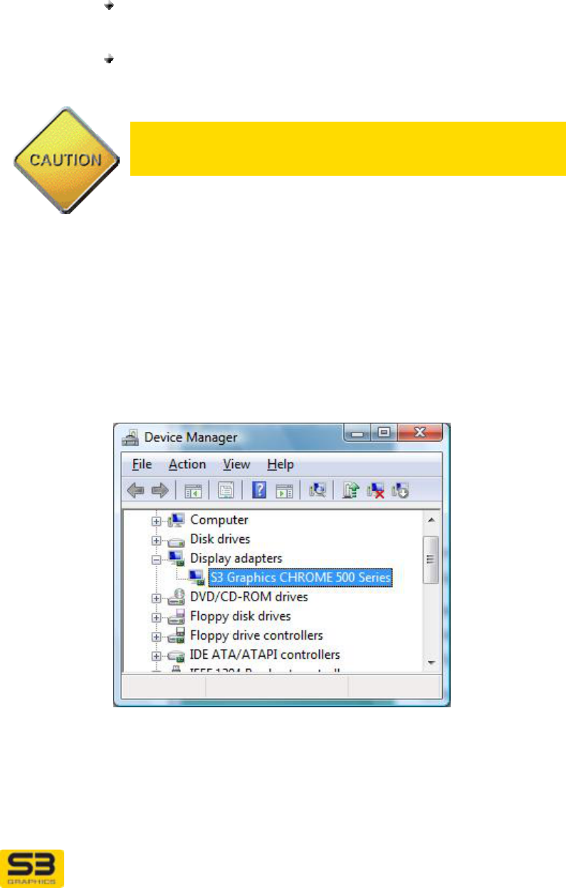
User Guide for Chrome 500 Series Graphics
SG195-A.1 10/20/2008
Page 134
Step 12. For the changes to take full effect, you must now reboot.
If you are going to physically remove your S3 Graphics
hardware: Click Start, Shutdown, Shutdown. Remove the
board from your system now before rebooting the computer.
If you will keep your current S3 Graphics hardware in the
computer: Click Start, Shutdown, Restart. Your computer will
restart.
Caution: Windows will not physically delete the S3Graphics
Driver and Utilities files. After reboot, Windows may be able to
identify your hardware and will try to reinstall the drivers.
13.3.3 Software Removal Using Device Manager
Step 1. Vista: Click Start. Right click Computer. Click Manage.
XP: Right click My Computer. Click Manage.
Step 2. The Computer Management window will appear. In the left panel,
click Device Manager.
Step 3. The right panel of the window will display a list of devices.
Step 4. Click the plus sign in the box preceding Display adapters.
Double-click S3 Graphics CHROME 500 Series (or other device
you wish to remove). Click Driver tab. Click Uninstall.
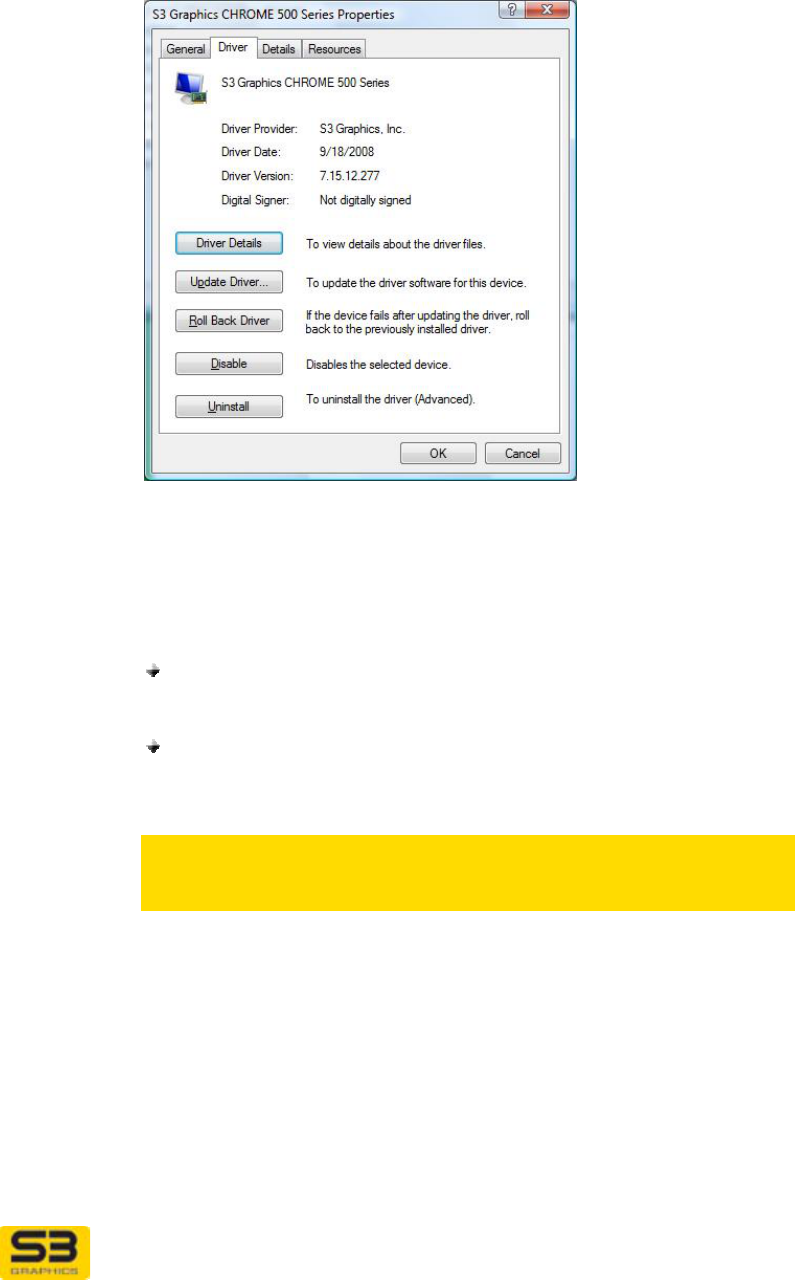
User Guide for Chrome 500 Series Graphics
SG195-A.1 10/20/2008
Page 135
Step 5. The Confirm Device Removal window will appear. Click OK.
Step 6. The System Settings Change window will appear, asking “Do
you want to restart your computer now?” Select No.
Step 7. For the changes to take full effect, you must now reboot.
If you are going to physically remove your S3 Graphics
hardware: Click Start, Shutdown, Shutdown. Remove the
board from your system now before rebooting the system.
If you will keep your current S3 Graphics hardware in the
computer. Click Start, Shutdown, Restart. Your computer will
restart.
Caution: Windows will not physically delete the S3 Graphics
Driver and Utilities files. After reboot, Windows may be able to
identify your hardware and will try to reinstall the drivers.
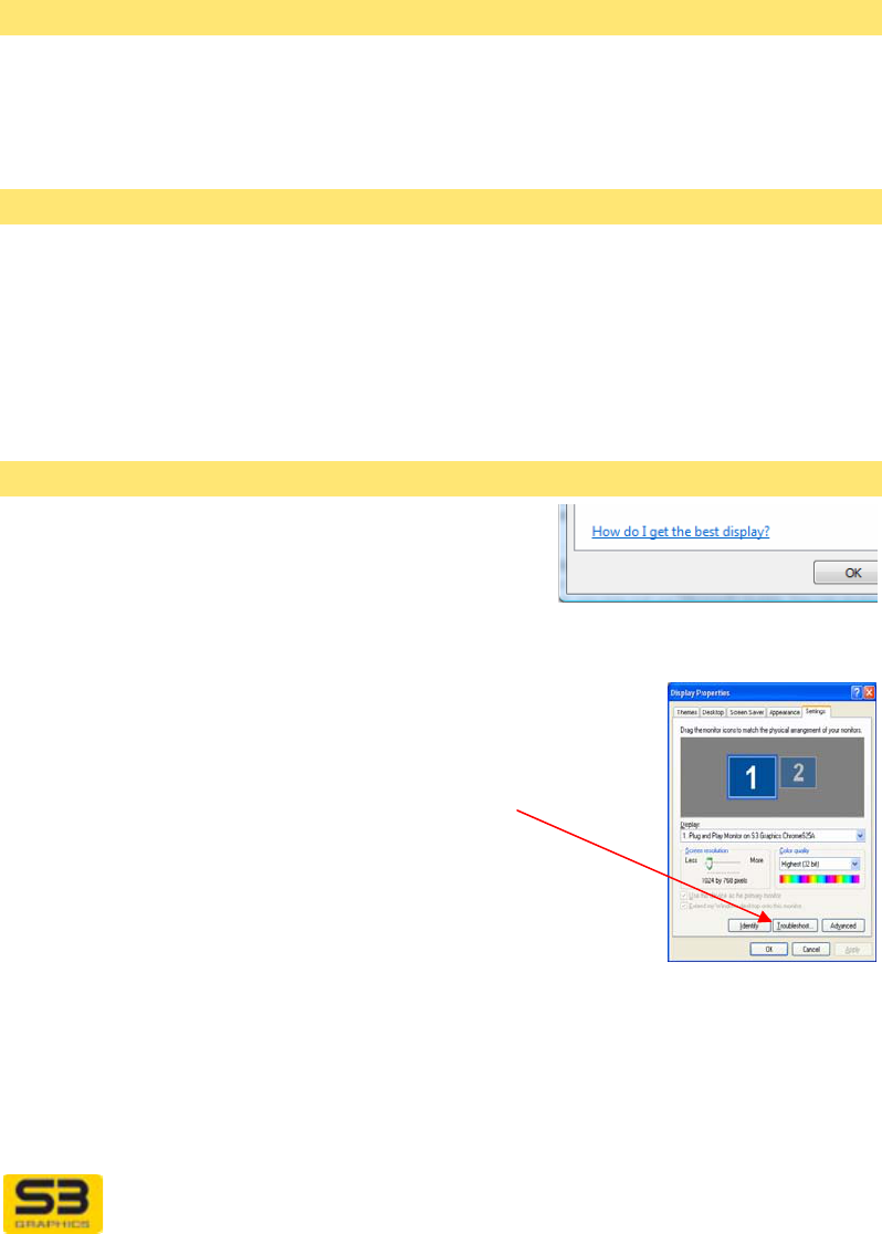
User Guide for Chrome 500 Series Graphics
SG195-A.1 10/20/2008
Page 136
SECTION 14 TROUBLESHOOTING
Below are some of the common answers and solutions available for questions
and problems that can occur with display driver installation and use.
No Display on System Boot
Verify that your graphics card is properly seated in its slot.
Verify that all display cables are properly connected to your card.
Verify that connected displays are plugged-in and receiving power.
Lost Monitor Information
If you are using an older model monitor, a BNC cable, a dongle, or a switch box,
important data from your CRT, DVI or HDMI monitor may not be transmitted to
your S3 Graphics adapter.
WORKAROUND: Use standard cables and DDC compatible display devices
which are capable of transmitting information to the adapter.
Use Video Display Help
The How do I get the best display? hyperlink
on the Windows Vista Display Settings page
provides a link to Windows Help and Support
information provided by Microsoft.
For Windows XP the similar link is Troubleshoot button for
Windows XP: To launch the Video Display Troubleshooter
in Windows XP, right click on any unpopulated area of the
Desktop. Click Properties. The Display Properties
window appears. Click Troubleshoot to launch the Help
and Support Center window for the Video Display
Troubleshooter provided by the operating system.
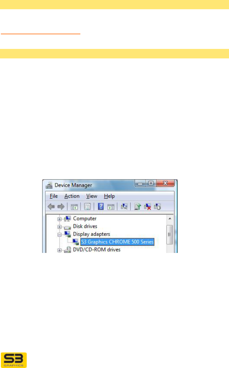
User Guide for Chrome 500 Series Graphics
SG195-A.1 10/20/2008
Page 137
HOW TO References
Many answers to common Windows questions are provided in the searchable
Microsoft Knowledge Base.
http://support.microsoft.com/ then click on Search Knowledge Base
Windows Driver Roll Back feature
If you encounter problems after updating your drivers under Windows Vista or XP,
you may use the Driver Roll Back feature to reinstall the previous “good” driver
and restore any driver settings that were changed when the new driver was
added.
To roll back to the previous version of a driver
Step 1. In Windows Vista or Windows XP, click Start, then Control Panel.
Step 2. In Windows Vista, click System & Maintenance, then click
System. In the left panel Tasks list, select Device Manager.
In Windows XP, double-click the System icon. This opens the
System Properties window. Click Hardware tab, then click
Device Manager button.
This opens the Device Manager window.
Step 3. Click the plus sign in the box preceding Display adapters.
Double-click S3 Graphics CHROME 500 Series (or other name
that matches your board or chip). Click Driver tab. Click Roll
Back Driver.
Note that the Driver Roll Back feature will be dimmed and will not
be available if this is the first driver installed for the device.
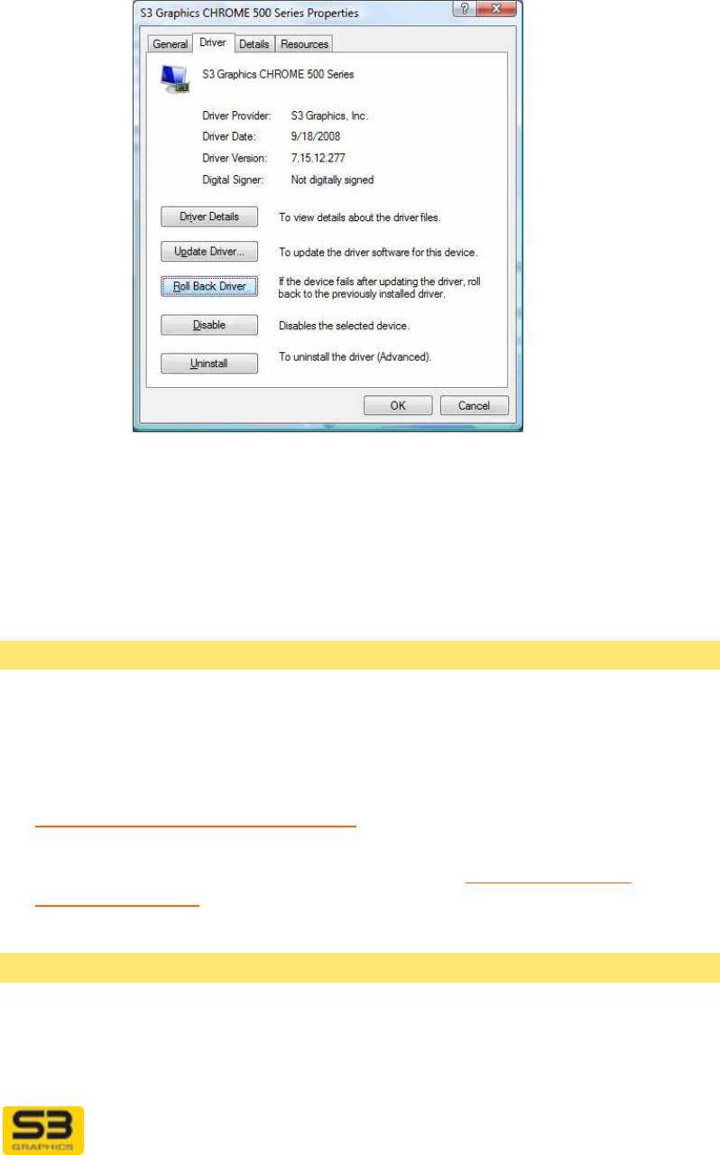
User Guide for Chrome 500 Series Graphics
SG195-A.1 10/20/2008
Page 138
Step 4. You will be prompted to confirm that you would like to roll back to
the previous driver. Click Yes.
Step 5. Windows will then restore the files and settings for the previously
installed display driver. Once the previous driver is restored, click
Close. You will then be prompted to restart your computer to
complete the driver roll back.
Software Updates
Windows Updates
Your S3 Graphics software has been tested with versions of the Windows
operating systems available at the time of the software’s release. Operating
system updates are available periodically from the Microsoft Windows Update
site:
http://windowsupdate.microsoft.com/
See also the additional updates discussed in the Tools for the Video
Enthusiast Section.
DirectX Diagnostic Tool
You can test the functionality of DirectX and view information about your system
and display hardware using the DirectX Diagnostic Tool.

User Guide for Chrome 500 Series Graphics
SG195-A.1 10/20/2008
Page 139
Step 1. Windows Vista: Click the Start button.
In the search box that appears just above the Start button (for
Windows XP, click Run), and type dxdiag.
This opens the DirectX Diagnostic Tool window.
Step 2. Click Display tab. (If you are using Multi-Monitor, then there may
be more than one Display tab.) On each Display page you can
view information about the currently installed hardware and drivers
for that device.
Step 3. With Windows XP only, you can click on the Test DirectDraw
and/or Test Direct3D buttons to verify that DirectX features are
working properly for that particular display. If you suspect that
there is a problem with a particular DirectX feature on your system,
you can temporarily disable hardware acceleration for DirectDraw,
Direct3D, or AGP Textures independently.

User Guide for Chrome 500 Series Graphics
SG195-A.1 10/20/2008
Page 140
SECTION 15 GLOSSARY
This glossary includes definitions for only a few of the terms used in the S3
Graphics User Manuals. Numerous on-line glossaries are available if the
graphics term you are looking for is not listed below.
Brightness - Visually, brightness reflects the intensity (or luminance) of the
image going from darker to lighter. In S3 ScreenToys Desktop color, brightness
represents the lowering or raising of the gamma curve. Brightness adjustments
cause all values on the gamma curve to move down or up by the same amount.
Contrast - Visually, contrast reflects the ratio between the lightest and darkest
elements in the image going from low contrast to high contrast. In S3
ScreenToys Desktop color, contrast represents the angle of the gamma curve.
Contrast adjustments decrease or increase the angle of the gamma curve while
keeping the (x, y) point on the curve fixed at (0, 0).
CRT – Cathode Ray Tube. Used in reference to an external analog display
device, the CRT has the 15-pin VGA connector as its standard interface.
DualView -- Microsoft’s term for extended desktop mode in Windows. Microsoft's
definition for DualView is available online at
http://support.microsoft.com/default.aspx?scid=kb;en-us;283674
DVI - Digital Video Interface, is a high-speed digital connection for visual data
types that is display technology independent. DVI provides digital and analog
support in a single connector and allows for plug and play through hot plug
detection, EDID and DDC2b. DVI is often used to describe a detachable flat
panel display device.
Gamma -- Gamma is the brightness of a display adapter's output. In practice,
gamma is differentiated from brightness and contrast by the way it affects the
adjusted output. Gamma adjustments do not change the bottom left point and the
top right point of the gamma curve. In the S3 ScreenToys Desktop color, the
Gamma slider allows you to adjust the gamma within a pre-determined range.
The value reported on the slider is relative and does not report an actual gamma
value.
HDMI – High-Definition Multimedia Interface is an uncompressed, all-digital
audio/video interface between any audio/video source, such as a set-top box, PC,
DVD player, or A/V receiver and an audio and/or video monitor, such as a digital
television. HDMI transmits all ATSC DTV standards and supports 8-channel
digital audio.

User Guide for Chrome 500 Series Graphics
SG195-A.1 10/20/2008
Page 141
Multi-Monitor – A Windows feature that allows multiple video cards to be active,
each one displaying a portion of the entire desktop. Support for two monitors can
be accomplished through the use of either two separate or one dual head
adapter. With two separate display adapters, there are two separate drivers
driving the separate displays, with each one displaying a portion of an extended
desktop. Dual Head adapters, such as S3 Graphics GPUs, simulate the
presence of two video cards with a single chip.
Primary View, Primary Monitor, Primary Display -- The Primary View display
is the display that holds the logon dialog box when you start the computer. This is
the display used for prompts and pop-up windows. Most programs will display
windows on the Primary Display when you open them. DirectX, Direct3D and
current DVD applications typically run full screen on the Primary Display. In
SingleView Clone mode all active display output devices are associated with this
Primary View.
Secondary View, Secondary Monitor, Secondary Display – A secondary
display may be any display monitor that is not the Primary View in a dual display
Multiple Monitor configuration. Once you select "Extend my Windows desktop
onto this monitor", the Windows desktop is enlarged and extended onto the
secondary display.
Once in extended desktop configuration, the Control Panel "Display Properties"
application allows you to select separate screen resolution and color quality
settings for the secondary display.
YUV – A color encoding format used to transmit color video images. YUV uses
less bandwidth than the three separate video signals in an RGB video
transmission. The two major components of YUV are:
Luminance (Y), or the brightness of an image pixel.
Chrominance (UV or CrCb), or the color of an image pixel.
THE END OF SG195