SABINE SW65 UHF BELTPACK TRANSMITTER User Manual 2
Sabine, Inc. UHF BELTPACK TRANSMITTER Users Manual 2
SABINE >
Contents
- 1. Users Manual 1
- 2. Users Manual 2
- 3. Users Manual 3
Users Manual 2
22
Sabine Smart Spectrum® Wireless
© 2009 Sabine, Inc.
Receiver Operation
Fig. 5d Tweek-n-Peek example
Fig. 5c Sabine Tweek-n-Peek
5.2. Parameter Control & LCD Display
5.2.1. One set of Controls for 1 or 2 Channels
Whether you have a one- or two-channel SWM6 or 7000 series receiver is ap-
parent by the number of LCD displays on the front panel. However, only one
set of control knobs is provided for either one- or two-channel receivers. Note
that in a 2-channel receiver, this set of controls is shared, and assigned to a
channel by pushing either the A or B Channel Select button (see Section
5.2.2). Your receiver uses Sabine’s Tweek-n-Peek™ digital control system.
Whenever you turn a control knob one click, the associated function is shown
on two lines of text display in the LCD. The large numeric display will indicate the
current parameter value. Additional turns/clicks change the parameter setting
and display the value as the change is made. After a few seconds of inactivity,
the LCD will revert to its default display (RF channel).
Sabine’s Tweek-n-PeekTM
Whenever you turn a control knob one click, the name of the corresponding
function is shown and the current edit setting is displayed on the LCD. This
applies for all the front panel knobs.
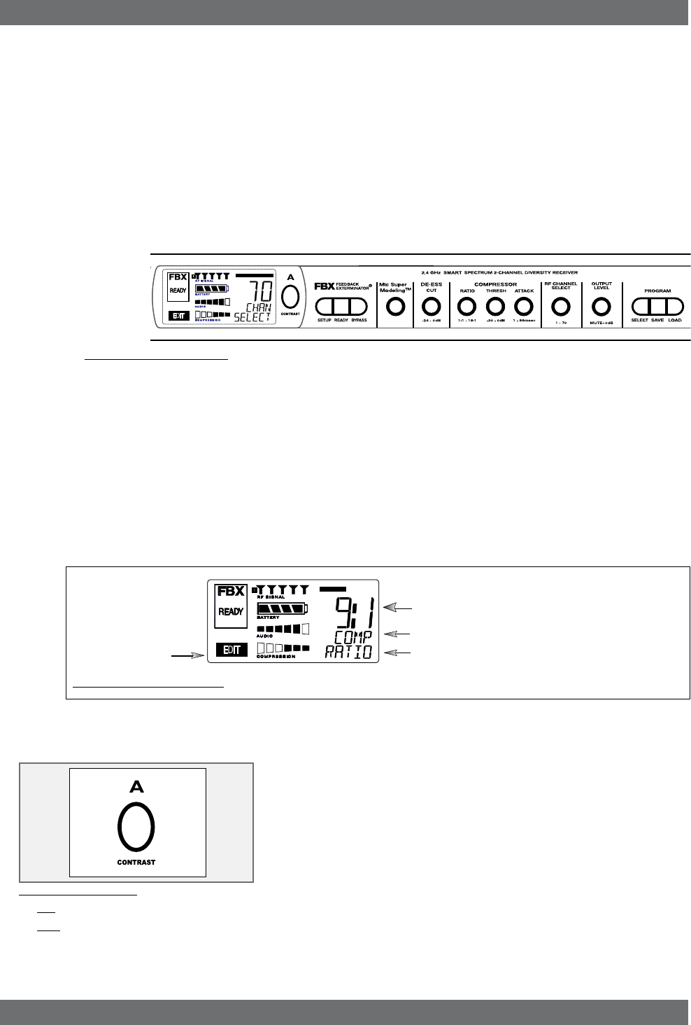
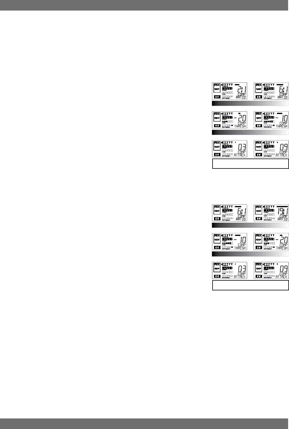
For example, if you turn the Compressor ratio knob one click, you will see the
current compression ratio in the Settings Display. The Text display will show
COMP on the first line and RATIO on the second. Subsequent turns will edit
that setting up or down, depending on the direction you turn the knob.
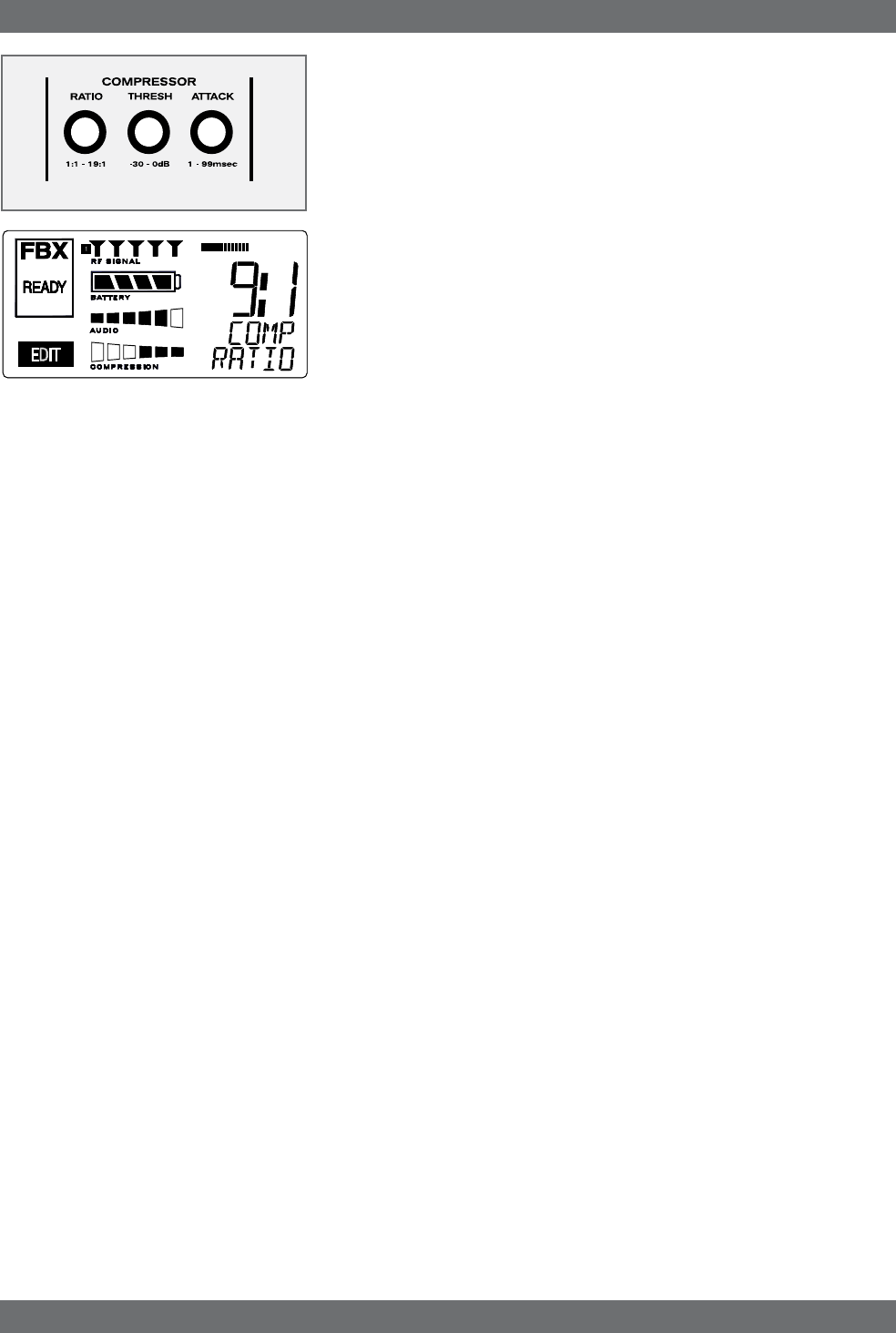
Since the control knobs are continuous rotary encoders with no end points,
the Relative Position Indicator (RPI) is a handy way of seeing where you are
in relation to the full range of the knob in question. In our compressor Ratio
example, if you are at a ratio of 9:1, about the middle of the range, the RPI will
display about one half of the bar. NOTE: The setting range of each control is
printed on the front panel below each knob.
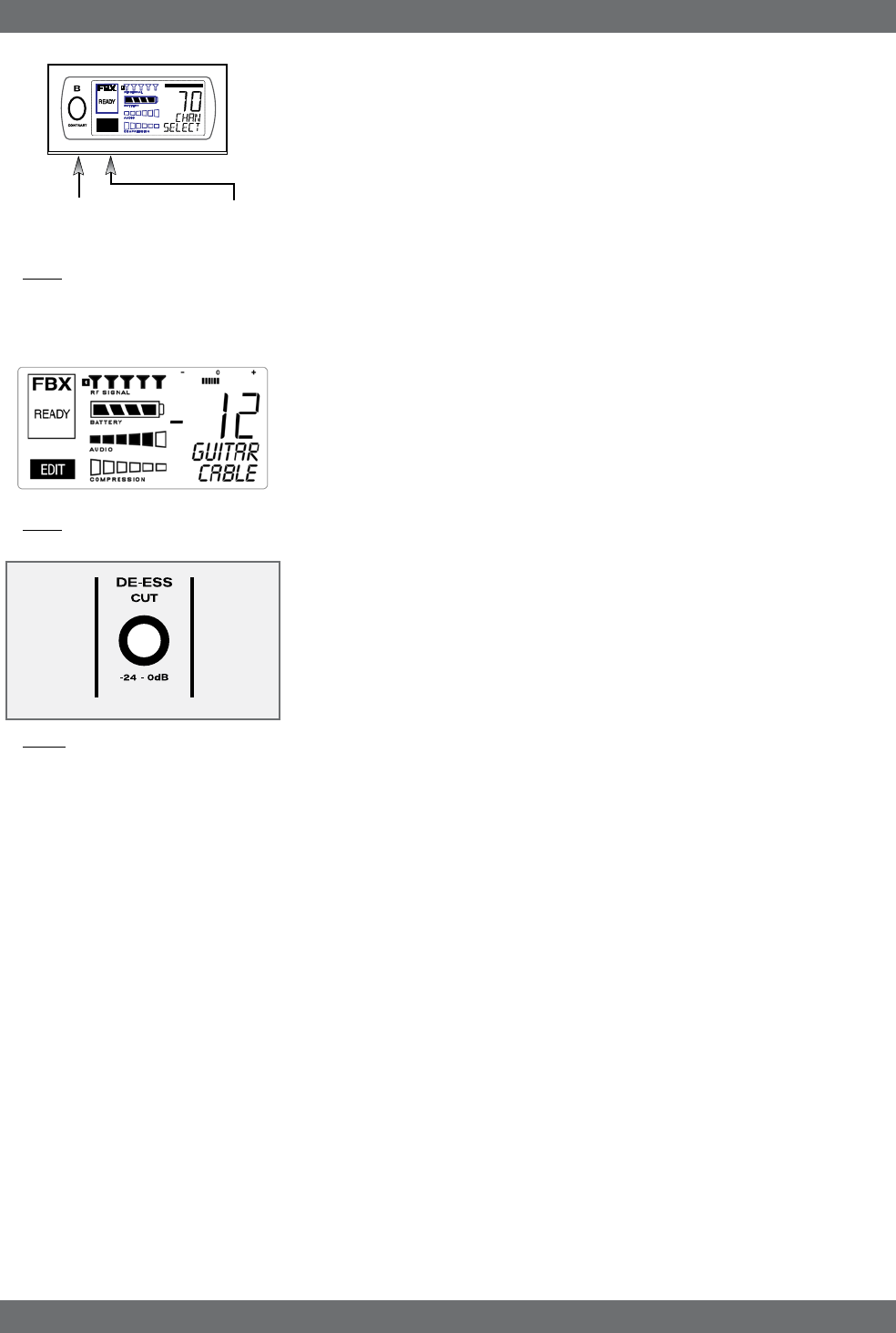
5.2.2. Channel Select / Contrast Button.
The elliptical button immediately adjacent to the LCD has multiple functions.
First, it adjusts the LCD contrast and viewing angle. Change the degree of
angle by pressing and holding the button down. The adjustment range will
cycle in a continuously reversing loop — when it gets to the maximum value
it reverses and begins to decrease in value. You can stop holding the button
down and initiate single button pushes to advance (or decrease) the contrast
setting incrementally.
In addition, the Contrast/Channel Select button has another function, in 2-
channel receivers only (SWM62 or 72-R or SWM62 or 72-NDR). Such units
feature two LCDs and two Contrast/Channel Select buttons. A single (without
continuing pressure) push assigns all Parameter Control knobs to the selected
channel. The button will light, the associated LCD will brighten, and the word
EDIT will appear in the lower left of the LCD, all indicating the active edit
channel. For the active channel, turning any Parameter Control knob will first
display (one click) and then adjust (subsequent turns) the settings of the func-
tion selected, indicating the changes in the Settings Display. For the inactive
channel, turning any Parameter Control knob will display the current setting
in that channel’s Settings Display. The channel must be activated in order
to change settings.
Relative Position Indicator
In our compressor Ratio example, if you are at a ratio of 9:1,
about the middle of the range, the RPI will display about one
half of the bar.
Function Display
The Function display will show COMP on the first line and
RATIO on the second.
Fig. 5e: Contrast button:
Tap to select which channel to control
Hold to adjust contrast and viewing
angle. Range of value is 1 - 30, 15 is
default.
EDIT will light in the chan-
nel display of the channel
being edited.
23 Sabine Smart Spectrum® Wireless
LIT-SWM6-7000-OG-EN-090215.indd - rr
© 2009 Sabine, Inc.
Receiver Operation
Fig. 5f
5.2.3. Special LCD Display Messages.
In addition to the Status and programmable information discussed above, the
text lines of the LCD Settings Display may also (under certain circumstances)
automatically override other displays. The conditions when this will occur and
the messages displayed are shown on page 19.
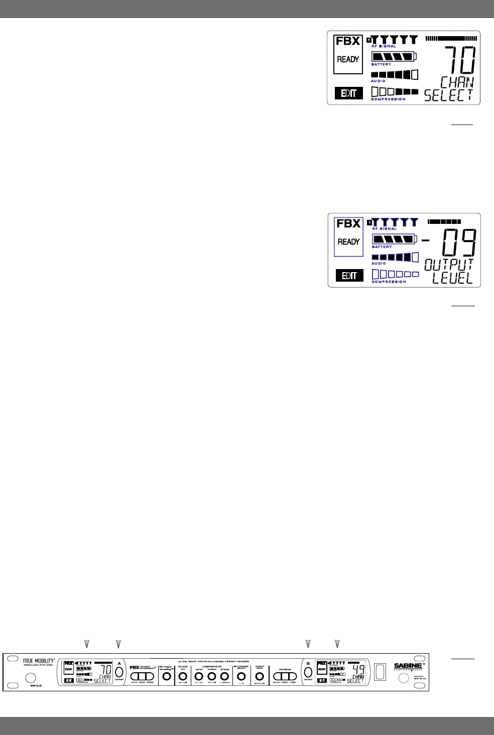
5.3. RF Channel Select
Range = 1 to 70 Choose the RF channel for this system. The transmitter must
have the same channel selected. Turn the RF CHANNEL SELECT knob until
the desired channel is displayed on the LCD. See chart (Appendix E) for exact
frequency of each channel.
NOTE: Dual channel receivers will not allow you to select the same RF channel
for both channels.
NOTE: Front panel RF Signal display will only register Sabine transmitters. It will
not show RF interference. Use the RF Scan function in the software to scan for
potential RF interference (see Section 13.4.2.5).
5.4. Output Level
Range = MUTE to 0 dB Adjust the output level to match the input character-
istics of the downstream component. Each tick of the output level knob adjusts
the level by ½ dB. The LCD displays this in 1 dB resolution, so it takes two ticks
of the knob to change the output level value on the LCD.
The output level varies from microphone level to line level, so if you are patching
the receiver to the mic level input of a mixer, turn down the level to avoid overdriv-
ing the mixer input. Minus 15 dB is a good place to start. If you are patching into
a line level device, turn up the receiver output. For best results, follow the golden
rule of gain structure: maximize gain at early stages in the signal path, to minimize
noise that will be accumulated and amplified by adding late-stage gain.
5.5. Channel Mixing
Your SWM Series two-channel receiver now has the ability to mix the
A and B outputs. In Channel Mixing mode both the A channel audio
and the B channel audio are mixed together, and are available on both
the A and B outputs.This is an advantage for several applications:
ExAMPLE: Guitarists who wish to have a spare guitar ready to go without re-
patching the output of the receiver to their pedal board or other processors. All
you have to do is turn the transmitter off for one guitar and turn on the other. The
audio is sent out through the same output of the receiver.
ExAMPLE: Sound techs who wish to use more mics than they have channels
for on their mixer. For example, you may have a mixer with only 8 inputs, but you
really need 12 mics for a show. You can combine the outputs of several pairs of
Sabine wireless mics and the show can go on without buying a new mixer.
You maintain separate control over all channel functions except output level.
Output levels are the same for both channels when in Channel Mixing mode,
and the ouput values appear on the A channel LCD.
5.5.1. How to Toggle Channel Mixing Mode
Press and hold both the A and B Channel Select buttons (the blue buttons) at
the same time. After a moment both buttons will be lit. This is your indication
that you are in Channel Mix mode. To go back to the standard mode, press
and hold the A and B channel select buttons again until the backlight of one
of the buttons turns off.
Fig. 5g
Ch. A
Channel
Select,
Contrast
Ch. B
Channel
Select,
Contrast
Ch. A
Display Ch. B
Display
Fig. 5h
24
Sabine Smart Spectrum® Wireless
© 2009 Sabine, Inc.
5.5.2. Controlling the Receiver in Channel Mixing
Mode
All functions are individually controllable for each channel when in Channel Mix
mode, except the output level, which is shared. Normally the active channel
for control is displayed in three ways: the blue button for that channel lights up,
the LCD gets brighter, and the word EDIT is shown. Use the Channel Select
buttons to choose the channel you wish to control.
In Channel Mix mode you still use the Channel Select buttons to choose the
channel to control, but you will only see one of these three indicators. The
word EDIT will be shown in the LCD of the channel selected for control. Look
carefully – this is your only indication of which channel you are controlling
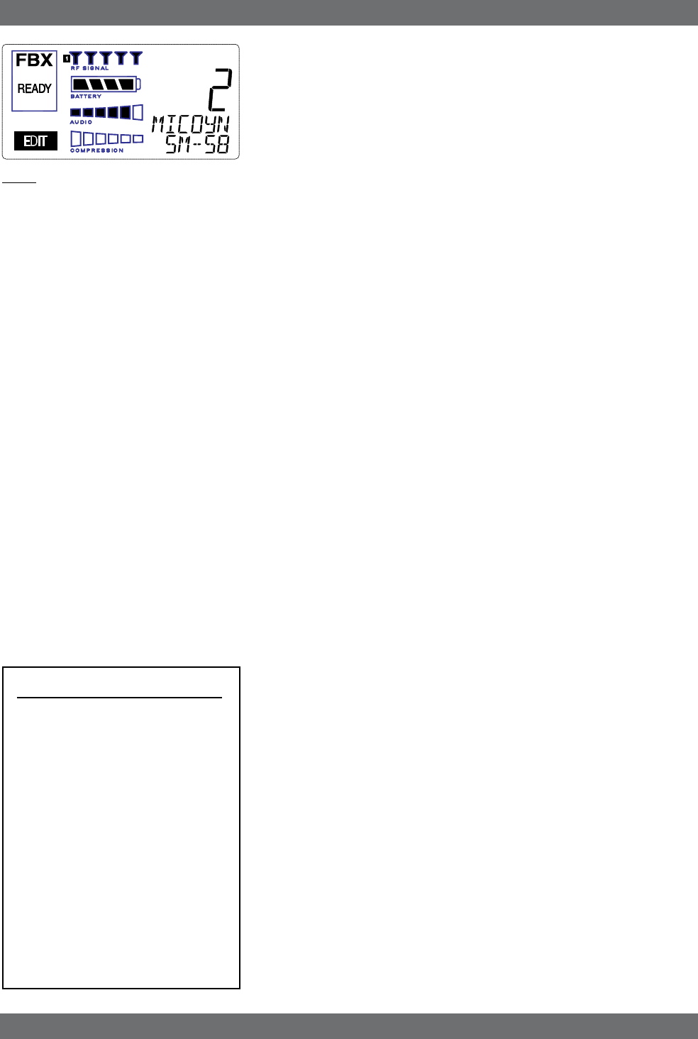
5.6. Guitar Cord Simulator (Beltpack Transmitter Only)
This feature allows you to fine tune the sound of your instrument while it is
patched into your Sabine wireless beltpack. The wireless sounds of guitars or
basses can be very different from the direct (patched with a cord) sounds. Your
Sabine wireless solves this problem by using a unique broadcast scheme that
gives full 20 to 20KHz frequency response. This results in a much fuller sounding
instrument (the bass response is finally there on a wireless!), and sometimes a
brighter sound, too.
How can this be? Your guitar cable can actually reduce your high frequency re-
sponse. We are all quite used to this slight rolling off of the high end, but the Sabine
wireless does not roll off, so your instrument may sound brighter then ever before.
Here’s where the Cord Simulator can help. Turn on your beltpack transmitter
and put it in GUI mode. To select GUI mode, open the beltpack, push the select
button a few times until you see the MIC or GUI display. Use the up/down button
to choose GUI. (See the Beltpack Quick Guide for detailed instructions). The
De-Esser knob on your receiver becomes your Cord Simulator knob. Turn the
knob counter-clockwise until your instrument sounds like it does when patched
direct.
The Cord Simulator replaces the De-Esser function only when a beltpack trans-
mitter is turned on and set to GUI mode.
5.7. Receiver Antenna Placement
One of the biggest potential problems in any wireless system is RF interference. Un-
derstanding wave interference patterns will help you to place and orient your receivers
and antennas properly, and thereby reduce the likelihood of RF interference.
Your receiver ships with two standard coaxial bipole antennas. Each antenna
picks up in a donut-shaped (toroidal) pattern, more or less equally in all direc-
tions, with null points directly above and below.
5.7.1. Multi-path Interference
Like sound waves, radio waves are subject to wave interference patterns pro-
duced by reflected or delayed waves combining with direct, unreflected waves,
converging upon a receiving antenna simultaneously. In the RF world this
phenomenon is called multi-path interference. As with audio comb filtering,
radio waves can combine additively or subtractively. Thus, mounting an antenna
close to a reflective surface can result in poor reception. For example, if weaker
than expected reception occurs, and the receptive part of the antenna (the top
3 cm) is close to a reflective surface (wall, large metal objects, etc.), you might
improve reception simply by repositioning, or re-aiming, the antennas.
In some situations — for example, those with difficult lines-of-sight, or when
transmitters and receivers are separated by a wall, or when receiver placement
options are limited — an extension antenna may be necessary to guarantee
reliable reception. Please refer to Section 12 for information about the advan-
tages and use of Sabine’s SWASS-EXT Extension Antenna Kit.
5.7.2. Receiver & Antenna Placement Tips
1. When possible, maintain line of sight from transmitter to receiver.
Consider the potential range of transmitter “roaming,” and locate your
receiver accordingly. If direct line of sight proves impossible or difficult,
consider using Sabine’s low-profile, active Extension Antenna Kit (SWASS-
Receiver Operation
Fig. 5k
Fig. 5j
EDIT
EDIT
Channel Select/Contrast
button (selects receiver
channel to edit)
Fig. 5i

25 Sabine Smart Spectrum® Wireless
LIT-SWM6-7000-OG-EN-090215.indd - rr
© 2009 Sabine, Inc.
EXT), which boosts the signal strength, extends the maximum distance
from transmitter to receiver, expands and focuses antenna sensitivity, and
allows antenna and receiver to be positioned further apart or in separate
rooms.
2. Decide on front or rear panel antenna mounting (to maintain line-of-
sight path). Antennas typically mount on the rear panel of your receiver,
but the included accessory SWA700 front mounting kit can be screwed
onto the front and connected via jumper to the back panel terminals. When
mounting receivers in a rack that is deeper than the receiver, move the
antennas to the front for improved reception. For any rack mounted re-
ceiver, try to keep the top 1.25 “ (3 cm) of both antennas extended outside
the sides of the rack (see Fig. 5h). Non-rack mounted receivers should be
oriented so that the antennas face the transmitters.
3. Maximize the distance between the receiver and light sources, such
as fluorescent bulbs or neon signs, which may emit very short-range,
broadband interference. These light sources should not be a problem in
normal circumstances, but, as a cautionary preventative, we recommend
a minimum distance of 3 meters (10 feet) between them and any receivers
or extension antennas.
4. Note the placement of any microwave ovens in the immediate vicin-
ity. Place any receivers or extension antennas as far away as is practical
from microwave ovens.
5. Mount receiver antennas at 90 degrees to one another, leaning away
at 45 degree angles, in the same plane. This will decrease the likelihood
that one antenna will be susceptible to the same orientation-specific
directional or multi-path problems that may affect the other one.
6. When using multiple receivers, try to maintain at least 1 foot (30 cm)
distance between antennas from different units. If you are rack-mount-
ing multiple receivers, you may want to avoid spacing them in adjacent
rack spaces, to maintain distance between antennas. When such antenna
spacing proves difficult or impossible, we recommend using Sabine’s
Antenna Distribution Amplifier (Sabine SWA6SS), which can help man-
age antenna configurations and, more importantly, improve system-wide
interference rejection. The SWA6SS works with up to six receivers.
7. In very rare instances, poorly shielded or malfunctioning computers or
digital effects units may cause RF interference. You can test whether
such units are the sources of such interference by switching them off one
at a time, and determining if interference rejection improves.
8. Turn on your system one component at a time, beginning with the
first receiver. If you don’t have a computer handy, keep all other receiv-
ers and transmitters switched off for the time being.
9. Use the RF Scan function included in the Remote Control Software.
This will give you a picture of the potential interference in your area, both
real-time and over time. Please refer to Section 13.4.2.5. for information
on Sabine Remote Control Software’s Automatic RF Scan function, which
will automatically determine the best RF channels to use.
10. Maintain a minimum distance of at least 3 meters (10 feet) between
transmitters and receivers or extension antennas. This can solve many
anomalies.
11. Be careful not to set more than one transmitter to the same channel;
each paired transmitter and receiver should be set to unique correspond-
ing channels, until all channels are receiving clearly and cleanly.
12. Once the physical placement of your receiver(s) and antenna(s) is
decided, proceed with the remainder of the setup process.
Receiver Operation
26
Sabine Smart Spectrum® Wireless
© 2009 Sabine, Inc.
Fig. 6a
6. MIC SUPERMODELING™
6.1. Introduction
Microphones come in a dazzling variety of shapes, sizes, polar patterns, frequency
response curves, phase response curves, etc. Few things arouse as much pas-
sion amongst audio engineers as discussions about what microphone to use in
a given application. Sound rental companies and recording studios proudly tout
their impressive microphone collections, and singers frequently favor a certain
brand and model number as “perfect for my voice.”
The only viable “please everyone” strategy is to stock a wide assortment of mi-
crophones. This is far easier for wired microphones than for wireless. Changing
a wired microphone is as simple as disconnecting one mic and connecting an
alternative — the same cable and same microphone stand allows easy inter-
changeability. At worst you might have to exchange microphone clips along with
the microphones themselves.
For wireless microphones, however, the situation is not so simple. With differ-
ent transmission frequencies, different proprietary designs, different types of
connectors (microphone to belt pack transmitter), and the matched-set nature
of transmitters and receivers, changing a microphone/transmitter is far more
complex.
Sabine has a better idea — Sabine’s proprietary Microphone SuperModelingTM.
With digital technology, it’s possible to start with the sonic signature of a high
quality microphone (such as Sabine’s standard condenser and dynamic capsules
used in our handheld series systems), and emulate the characteristics of other
popular microphones—all at the twist of a knob. You won’t have to change mi-
crophones, cables, connections, or receivers, interrupt a performance, or even
get up from your mixing chair! Best of all, you will have an instant answer to
a variety of demands from singers and speakers for their favorite microphone
— even if they pass the microphone around.
6.2. Emulation Choices
Each Sabine receiver comes equipped with 7 different SuperModel microphones
available per channel. Four of these (Shure SM-58, Shure Beta 58, Audio Tech-
nica ATM 41A, and AKG D-3800)* are designed for use with either of Sabine’s
dynamic handheld microphone/transmitters (SW60 or 70-H13 and H15). The
remaining three (Shure Beta 87A, AKG C535EB, and Audio Technica ATM 89R)*
are designed for use with Sabine’s condenser handheld microphone/transmitter
(SW60 or 70-H19). In addition to these SuperModeling choices, you may prefer
to use Sabine’s high quality microphones “just the way they are;” i.e., without
emulation.
Telemetry information sent by the handheld transmitter to the corresponding re-
ceiver (or receiver channel for a 2-channel unit) identifies the type of transmitter,
and loads the appropriate emulation library. Note that beltpack transmitters also
send telemetry that turns off the Super Model option, as this feature is designed
to work only with handheld microphone/transmitters.
6.3. Mic Modeling Front Panel Control
Simply turn the parameter control labeled “Mic SuperModelingtm” to scroll through
and select the microphone you wish to emulate. The first click of the knob will
show the current setting, without changing it; additional turns will change the
emulation that is active. The top text line of the Settings Display will read either
MICDYN (dynamic) or MICCON (condenser) depending on the telemetry infor-
mation sent by the handheld; the bottom line will display the microphone being
emulated. Note that one choice is to bypass modeling, and simply utilize the
excellent quality of the Sabine microphone capsules. In this case the bottom
text line will simply read OFF. Finally, whenever telemetry information indicates
that a belt pack transmitter is the RF source, or if a handheld transmitter is re-
placed by a belt pack with the same receiver (or some such other unpredictable
event transpires), the Settings Display will read MICMOD/OFF whenever the Mic
Modeling knob is turned.
Mic SuperModeling™
Sabine Mic SuperModelingTM
SuperModelingTM Dynamic Models*:
- Shure SM-58
- Shure Beta-58A
- AKG D-3800
- Audio-Technica ATM 41a
SuperModelingTM Condenser Models*:
- Shure Beta 87A
- AKG C535 EB
- Audio-Technica ATM 89R
- Crown CM200A
*Company names, product names, and
trademarks listed as modeled are the
property of their respective owners and are
used only to identify evaluated microphones
used to develop digital processing; they in
no way imply association, endorsement, or
approval by any named manufacturer.
27 Sabine Smart Spectrum® Wireless
LIT-SWM6-7000-OG-EN-090215.indd - rr
© 2009 Sabine, Inc.
There are no modeling settings for lavalier or headset microphones — mic
placement makes these an unrealistic choice for modeling. NOTE: other lavalier
microphones can be used with the Sabine Beltpack Transmitter.
6.4. Future Microphone Modeling Choices
When Sabine adds to the library of “virtual microphones” that are modeled by
the receiver DSP, these will be made available as a firmware upgrade from the
Sabine web site, www.Sabine.com.
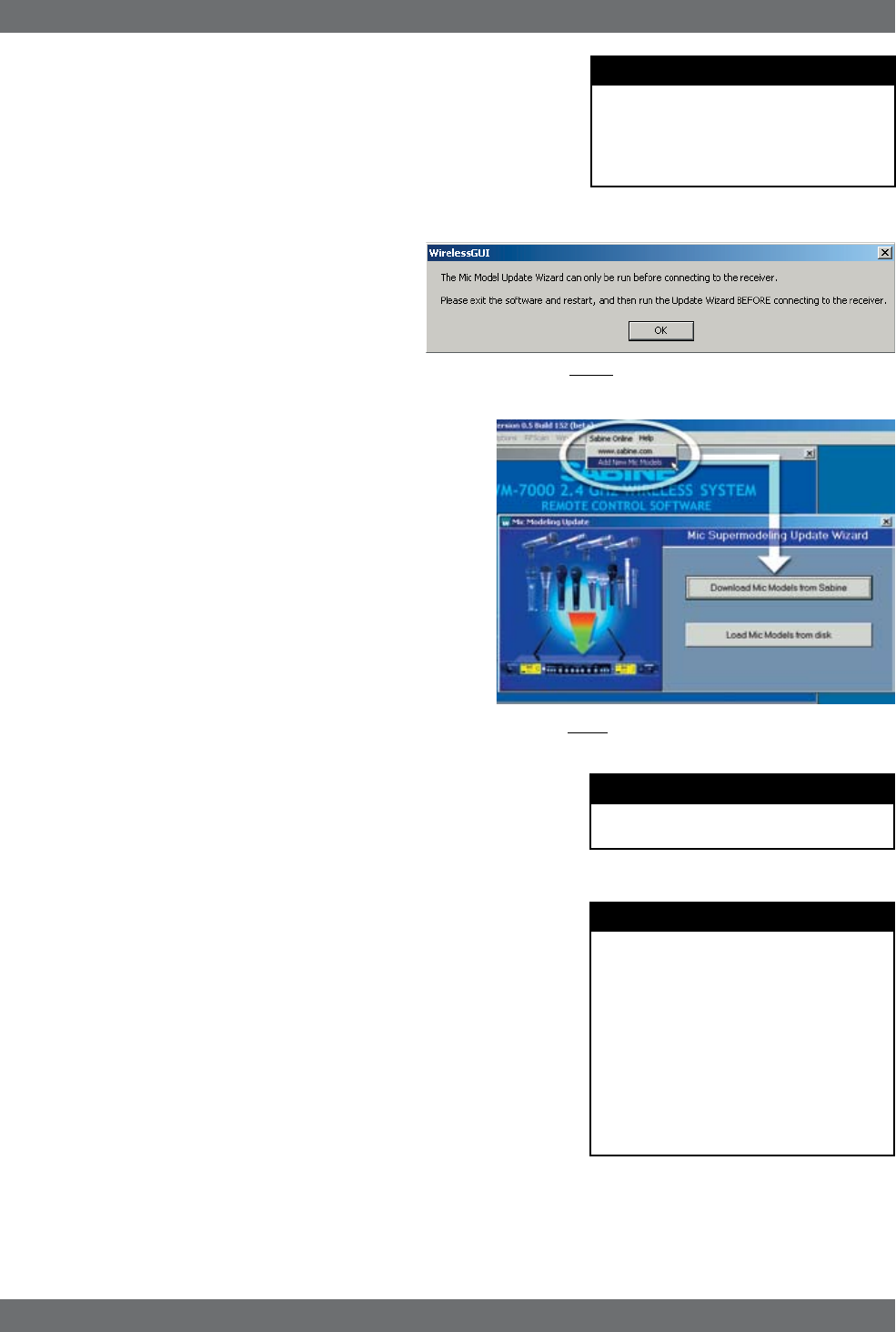
6.4.1. Mic Model Upgrade Instructions
New Mic SuperModelingtm “virtual microphones” can be
downloaded easily using the remote control software
on your PC. NOTE: The Mic SuperModeling Update
Wizard can be accessed only from the initial soft-
ware startup menu (prior to connecting to a receiver
or entering Demo/Edit Mode). If you have already con-
nected and attempt to access the Upgrade Wizard, the
message box at right will appear (Fig. 6b):
To download new mic models:
1. With your PC connected to the Internet, pull down the Sabine
Online menu in the software menu bar and select “Add New
Mic Models.”
2. Click the “Download Mic Models from Sabine” and follow the
dialog box instructions.
3. The last dialog box will allow you to either connect to a re-
ceiver and update the mic models on that receiver, or cancel
and complete the upgrade process at a later date. Note that
this dialog box will show the actual file path of the new mic
model file.
Upgrading from a disk or previously downloaded files:
Mic SuperModeling™ files already downloaded can be flashed
into your receiver using the second option “Load Mic Models from
disk.” Clicking this button opens a dialog box (default directory is
your “Sabine” directory).
NOTE: File name will always be “micmodels.smm” and will in-
clude all mic models available up to the date the file was downloaded.
Mic SuperModeling™
Fig. 6b
Fig 6c
NOTE
A very short crossfade of the audio sig-
nal occurs when switching between mic
models. This ensures no digital artifacts
will occur when you change the sound
of the mic.
NOTE
Mic SuperModelingtm is not available using
beltpack transmitters.
CHANGING CAPSULES
Sabine’s Mic SuperModeling™ function
requires a baseline characteristic for the
capsule in use. Therefore, after changing
capsules, you will need to “tell” the trans-
mitter which capsule is now attached.
NOTE: this is only necessary when the
capsule is changed.
See Appendix G for instructions on how
to reset your transmitter after changing
capsules
28
Sabine Smart Spectrum® Wireless
© 2009 Sabine, Inc.
FBX Feedback Exterminator
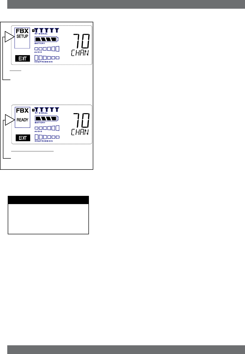
FBX SETUP NOTE
LCD “READY” Flashing
As you get close to the end of the setup
procedure, READY will begin to flash on
the LCD. Stop raising the gain! The FBX
will now go into Ready Mode.
7. FBX FEEDBACK EXTERMINATOR®
SETUP Indicator
Fig. 7a
Fig. 7b: READY Indicator
NOTE: make sure READY is displayed before
using your system for a performance.
7.1. FBX Introduction
There are two types of FBX filters, fixed and dynamic. Both operate automati-
cally. There is no audible difference between fixed and dynamic filters in terms
of sonic purity; the difference arises in their application.
7.1.1. FBX Fixed Filters
Fixed filters are set automatically during the FBX SETUP and will not change
frequency until manually reset.
7.1.2. FBX Dynamic Filters
Dynamic FBX filters also set automatically, but can change frequency, on a
rotating basis, as the need arises.
7.1.3. Balancing Fixed & Dynamic Filters
Each channel of your receiver offers a total of 10 FBX filters (combined fixed
and dynamic), which can be used as needed to exterminate feedback. The
default setting of 7 Fixed and 3 Dynamic can be changed to 8 Fixed and 2
Dynamic using the DIP switches on the back of your receiver (see Appendix
D FBX Configuration DIP Switch), or to any configuration using the Remote
Control software (see Section 13).
If you follow setup instructions for setting FBX filters, your receiver will auto-
matically exit SETUP mode (enter READY status) after all Fixed filters, and
the first Dynamic filter, have set. In the default condition, this means you
will have set eight filters (seven Fixed and one Dynamic), with two Dynamic
filters still unset and remaining on standby alert. If you wish to set fewer
filters, press the READY button before SETUP automatically exits, after you
have set enough filters to safely achieve your desired gain level. In that
case, in the factory default condition, you will reserve three unset Dynamic
filters for standby.
7.1.4. FBX Filter Width
Sabine’s experience and testing with filters and sound quality along led us to
decide upon a default FBX filter width of .10 (one-tenth) octave as the optimal
notch width, able to eliminate feedback without affecting music programs.
If, with all filters properly set, feedback is still a problem, FBX filters may be
set to .20 (one-fifth) octave width. This wider filter setting will help to better
eliminate feedback trouble areas, but may also affect music programs slightly.
Therefore, the wider setting is generally considered to be appropriate where
speech (less demanding than music) is the primary application of the Sabine
Wireless system. You can globally change FBX filter width by repositioning
a rear panel DIP switch, to change from .10 to .20 octave (see Appendix D
FBX Configuration DIP Switch), or by adjusting filter width using the True
Mobility® Remote Software (which allows a range of widths from .01 to 1.0
octave). You may also mix filter widths, either by adjusting individual filter
widths using the Remote Software, or by changing the DIP switch position
during setup. The width of any set filter will always be determined by the
position of the switch at the time the filter is created.
7.2. FBX Set Up
Follow these easy steps to obtain the maximum gain and protection from
feedback. Sabine FBX employs a very fast and quiet setup mode to make it
easy to use.
1. Place the speakers in the positions where they will be used during the
program.
2. If there is any equipment with a noise gate in the signal path, you MUST
DISENGAGE the noise gate(s) prior to the setup procedure. You may
reengage these noise gates upon conclusion of your FBX setup.
3. Patch your Sabine receiver into the mixer or amp channel. Set the amp
master output gain to a normal operating position.
NOTE: The level of your power amplifier should be set to a level that allows
a healthy gain structure prior to the amplifier. If your amplifier is turned up
29 Sabine Smart Spectrum® Wireless
LIT-SWM6-7000-OG-EN-090215.indd - rr
© 2009 Sabine, Inc.
FBX Feedback Exterminator
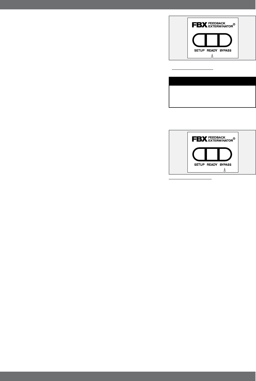
Fig. 7c: READY Button
Tech Tip
READY & Locked Fixed
READY = Lock Fixed on other Sabine
FBX products
fully, and your mixer meters show little movement when signal passes through,
then your amplifier will have to work harder to process the weak signal. You
will improve the performance of your sound system and lower system noise
by reducing the gain on your power amp and increasing your mixer gain. FBX
response time will also be better with proper gain structure.
4. First, turn on your receiver and select a clear channel (no RF Signal bars
showing). Then turn on your wireless transmitter or handheld microphone
and select the same channel, Now turn on the mixer (gain low), then any
other accessories, and finally the power amp. If you are using a graphic EQ,
adjust only for the desired tonal qualities, but do not notch for feedback!
5. With the microphone turned on, raise the Output Level of the receiver slowly
until a strong input signal at the mixer is apparent. The microphone should
now be audible.
6. Now you are ready to set FBX filters. Press and hold SETUP (far left button)
on the wireless receiver, until the word SETUP in the channel LCD flashes
4 times, then stops flashing. This will clear any FBX filters already in place.
NOTE: You should do this each time you move your sound system, change
a sound system component, or relocate your microphone. Your Sabine True
Mobility Wireless System will remember its settings from the last time you
turned the unit off.
7. During Setup mode, do not talk into the microphone or pass audio program
through a transmitter. This may cause the Sabine True Mobility™ system to
set inappropriate filters. The only appropriate use of the setup mode is to
create and filter feedback. SETUP must be exited prior to normal microphone
usage. This happens automatically after setting FBX filters, or you may exit
manually by pressing READY at any time.
8. Identify the primary usage positions, and likely feedback-prone locations, in the
potential movement range of the wireless microphone. Take the microphone
to the first of these locations.
Fig. 7d:BYPASS Button
9. Slowly raise the mixer channel gain to the point of feedback — and then slowly beyond, until you hear the chirping tones
of feedback quickly being eliminated by FBX filters setting. Stop raising gain after 2 or 3 feedback tones have chirped and
corresponding FBX filters have set. Rest assured that any feedback that occurs will be at a quiet volume, and very short
in duration.
10. Move the microphone to another area of use and slowly raise gain until FBX eliminates a few more feedback tones (2 or
3). Repeat this step until the word Setup automatically disappears and the word READY appears. This indicates your unit
is ready for operation. The total number of filters available for feedback filtering is 10; in the factory default setting, your unit
will automatically enter READY mode when the eighth filter is set. Alternatively, you may enter READY status with fewer
fixed FBX filters in place, simply by pressing the READY button at any time. NOTE: Be sure that the word READY appears
in the FBX section of your receiver LCD during performance or any normal operation.
Any feedback that occurs after setup will be eliminated by dynamic filters, which remain in reserve to catch surprise feed-
back if it occurs during performance/operation.
In most instances you will experience an additional gain of 6-9 dB before feedback when using the Sabine True MobilityTM
System. Precise results will depend on system and acoustical considerations.
All fixed filters in place will remain set until the Setup button is pushed and held as described in step 6. All dynamic filters
will remain in place until new feedback occurs (when they will move to the new frequency), or until the Setup button is
pushed and held. Your True Mobility receiver will remember its FBX (and all other) settings even if the power is turned off.
See Section 14 for a complete discussion of Sabine FBX Feedback Exterminators®.
7.2. FBX Bypass Button
The Bypass button bypasses only the FBX Section, and not the additional signal processing (Parametric Filters, Hi/Lo Cut, De-es-
sing and Compression) available in the Targeted Input Processing section of the Sabine True Mobility™ Wireless Receiver.
NOTE: You can easily bypass Compression signal processing by turning the Compressor Ratio knob counterclockwise until
you get to 1:1 ratio, and the De-esser signal processing by turning the De-esser knob clockwise until you get to 0 cut.
30
Sabine Smart Spectrum® Wireless
© 2009 Sabine, Inc.
8. COMPRESSOR/LIMITER OPERATION
8.1. Basics of Compression
The dynamic range (how loud we can hear to how quiet a sound we can detect)
of the human ear is far greater than the capability of sound systems to repro-
duce. Although some of this equipment limitation is at the upper extreme of the
dynamic range (where too loud a signal will produce distortion), much of the
restriction occurs at the low level end, where the signal disappears below the
“noise floor” of the circuitry.
A compressor (or in its most powerful form, a limiter) is the most widely used tool
for controlling dynamic range. In the simplest terms, a compressor is designed
to squeeze the dynamic range of an audio program; i.e., to make quiet signals
louder, and loud signals quieter. A compressor becomes a limiter when the
compression ratio (the ratio of the input gain change to the output gain change)
is so high that the output level effectively won’t rise above a “brick wall” ceiling,
regardless of how much the input gain increases (typically a ratio of 10:1 and
greater).
A compressor acts like an “automatic mix engineer” with a hand on the fader and
an inhumanly fast reaction time. When the input level increases, the “engineer”
drops the fader; when the level decreases, the fader is raised. When the amount
of fader compensation equals the variation in signal level, the output level of the
audio program will sound consistent.
The practical benefits of compression and limiting include:
1. Speaker protection. A compressor will control sudden level peaks and
prevent your speakers from damage. Most often in this type of application,
the compression ratio is high enough to qualify as a limiter.
2. Perceived increase in loudness. Because compressed peak levels are kept
from rising as high as uncompressed signals, you gain headroom for your
audio program and can raise its overall average gain. Compression is often
added to the entire audio mix, both in live sound and recording, to increase
its perceived loudness.
3. Achieving more consistent levels. For expressive instruments or vocals,
which may have a large dynamic range, compression can help maintain
more consistent mix levels. So a speaker who varies from a whisper to a
shout will not disappear or stand out in the mix, relative to other less dynamic
instruments or vocals. Vocal level variations are also common when multiple
users share a single microphone, due to differences in voice volumes and
mic-to-mouth positions from one user to another. Compression will help even
out such variations as well.
8.2. Using the Compressor
Compressor knobs are located immediately to the right of the FBX and De-Esser
controls. The controls consist of standard Ratio, Thresh (threshold) and Attack
knobs, and a horizontal gain ladder in the LED display shows compressor gain
reduction.
Ratio: Compression ratio is the ratio of the input gain change to the output gain
change. The compression ratio on your Sabine Wireless ranges from
1:1 to 19:1, in increments of 1 dB. Set Ratio to 1:1 to bypass Compres-
sor.
Thresh: Compression threshold sets the input level at which the compressor/
limiter begins to act on the signal. The input level threshold at which
compression is engaged can be adjusted from -30 dBv to 0 dBv, in
increments of 1 dBv.
Attack: Compressor attack time sets the speed with which signal compression
begins once an input signal exceeds the threshold level. The range
may be adjusted from 1 to 99 mS, in 1 mS increments.
Compressor Limiter
31 Sabine Smart Spectrum® Wireless
LIT-SWM6-7000-OG-EN-090215.indd - rr
© 2009 Sabine, Inc.
Compressor Limiter
Gain: (Output Level) Since the output gain is attenuated whenever the input
gain exceeds the compression threshold, the overall output level of a
compressed signal will be reduced. Commonly, this reduced output gain
is compensated for by raising the level of the output signal (the term is
“gain make-up”). Output Level range may be adjusted from mute (minus
infinity) up to +20 dB, in increments of 1 dB (depending on input).
8.3. Suggested Compression Settings
8.3.1. Vocal Settings
The renowned expressiveness of the human voice is due in large part to its
dynamics. A vocal that varies from a whisper to a scream has a strong emotional
impact, but those same dynamics present a challenge to the sound engineer.
Ideal vocal compression maintains some dynamic range while keeping the
vocal the focal point of the mix.
Ratio: A soft voice might require a ratio of 2:1, whereas a loud voice might
require a ratio setting of 6:1.
Thresh: The higher the threshold setting, the more signal is required to initi-
ate compression. Ideally this should be set to reign in peak levels,
and allow signals of lower gain to pass uncompressed. Threshold
settings will depend on the nature and variety of the signal source.
Strong vocalists will require a different threshold than quiet speak-
ers or singers.
Attack: Short attack times usually work well for voice. However, too strong
a compression ratio, too low a threshold, and too fast an attack may
attenuate speech consonants, which provide important intelligibility
cues to the audience, thus compromising clarity.
8.3.2. Guitar Settings
Ratio: A high compression ratio (with gain makeup) will add sustain to
held notes and chords.
Thresh: Moving the threshold will change the audible thick/thinness of
the guitar tone, but generally you want to compress all the notes
played.
Attack: Be wary of too quick an attack, which may reduce the percussive
attack of the guitar notes.
In general, be wary of too much gain makeup, and too high a compression ratio,
which may make a noisy guitar amplifier more objectionable. Ratio settings might
range from 6 to 20:1, threshold variable, slower attack, soft knee, output gain
boosted slightly to significantly depending on amount of compression.
8.3.3. Bass Guitar Settings
Bass players use a variety of techniques, often in the same song, that can
benefit from compression. Compressing bass evens out peaks and keeps the
bass level in the mix.
Ratio: Set to 4:1
Thresh: Set to compress peaks only
Attack: Quick attack, medium release, hard knee (try various release set-
tings, depending on the speed of notes played)
Gain: Output boosted slightly
ratio
thrEsh
attaCk
ratio
thrEsh
attaCk
Vocals
Short attack is better for vocals. Be careful not
to over attenuate speech consonants.
Soft voice Loud voice
Soft voice Loud voice
Guitar
Less Sustain More Sustain
Thinner sound Thicker sound
Be wary of too quick an attack, which may re-
duce the percussive attack of the guitar notes.

32
Sabine Smart Spectrum® Wireless
© 2009 Sabine, Inc.
8.4. Possible Compression Trouble Areas
Like any signal processing, compression can be misused, and improper appli-
cation may cause undesirable side effects in the audio signal. Some of these
problems include:
1. Noise. If the threshold for compression is set too low, and the output gain is
raised substantially to make up for the gain loss of compression, the resulting
output signal can be noisy. This is because the overall signal must be raised
significantly to produce the same audible level, and the noise floor of your
equipment will be amplified unnecessarily. This problem will be exagger-
ated if the input signal level to the compressor is very low (which will already
degrade the signal-to-noise ratio).
2. Breathing. In situations where the compression ratio is high, the threshold
is low, and the release time of the compressor is short, the noise floor will
modulate up and down as the audio signal rises above and falls below the
threshold.
3. Over-compression. Applying too much compression to a mix can sometimes
result in such evened-out dynamics that the “life” of the music or speech has
been removed or curtailed. Dynamic variation may be a major component of
a performer’s message and command of the audience; don’t remove dynam-
ics, just control them. This may be particularly true for percussive musical
instruments such as drums.
8.5. Release & Knee Settings
Two other important compressor variables are release time and knee. Release
time adjusts the speed with which compression stops and output gain returns to
unity with input gain, once the input signal falls below the compression threshold.
Knee refers to the degree with which the full ratio of compression is imposed once
the input level threshold is approached and exceeded. A “hard knee” changes
from no compression to maximum compression exactly and immediately at the
threshold crossing; a “soft knee” gradually imposes the full compression ratio as
the input gain approaches and exceeds the threshold. In Sabine products, the
“softness” of a knee can vary from 1-40, with the higher level representing the
“softest” character. In such a setting, slight compression will begin well below
the compression threshold, increase as the input gain crosses the threshold,
and reach full compression well above the nominal threshold.
Values for release time and knee are set at the factory: default release time is
250 mSec, and the default knee setting is a “soft” setting of 20. These defaults
can be temporarily changed or reprogrammed using the Sabine True MobilityTM
Remote Software (see Section 13 for details).
Compressor Limiter
33 Sabine Smart Spectrum® Wireless
LIT-SWM6-7000-OG-EN-090215.indd - rr
© 2009 Sabine, Inc.
9. DE-ESSER
9.1. De-mystifying De-essers
Certain consonant sounds produced by the human voice contain more energy
than others, and have the potential to overload a microphone capsule. This
can produce a disproportionately harsh result when amplified through a sound
system, and/or recorded to analog or digital storage media. The most common
and obvious of these sounds (in English and many languages) is the “ssss”
sound, associated with pronunciation of both “s” and soft “c” consonants, also the
consonants “t,” “f,” “x” and sometimes “d.” The technical term for this particular
vocal sound is “sibilance,” and the devices that control such sounds are typically
called “de-essers” (or sometimes sibilance controllers). The frequency range of
sibilance will vary depending on the singer/speaker, the consonant involved, the
orientation to the microphone, the microphone itself, and the normal variations
in human vocalization. Cardioid- pattern condenser microphones are especially
susceptible to sibilance problems, but the problem can also occur with other types
and patterns of microphones. The range of frequencies affected by sibilance
starts above 2 KHz, and generally tapers off above 10 KHz; in other words,
sibilance is primarily a problem associated with higher frequencies (though not
the upper octave of human hearing).
9.2. The Sabine De-esser
The Sabine De-esser is essentially a type of frequency-band compressor, active
in the 2-10 KHz range, and inactive below 2KHz and above 10 KHz. Sabine’s al-
gorithm works by dynamically comparing band-specific and associated harmonic
energy levels to the total signal energy. When spikes are detected that correspond
to sibilance, a shelving filter is imposed on the appropriate frequency bands, and
remains in place only for the duration of the sibilance. High frequency energy
levels that remain below the comparison threshold do not trigger de-essing, and
lows and highs outside the sibilance range are also passed unprocessed and
unaffected. This means the Sabine De-esser is effective but transparent.
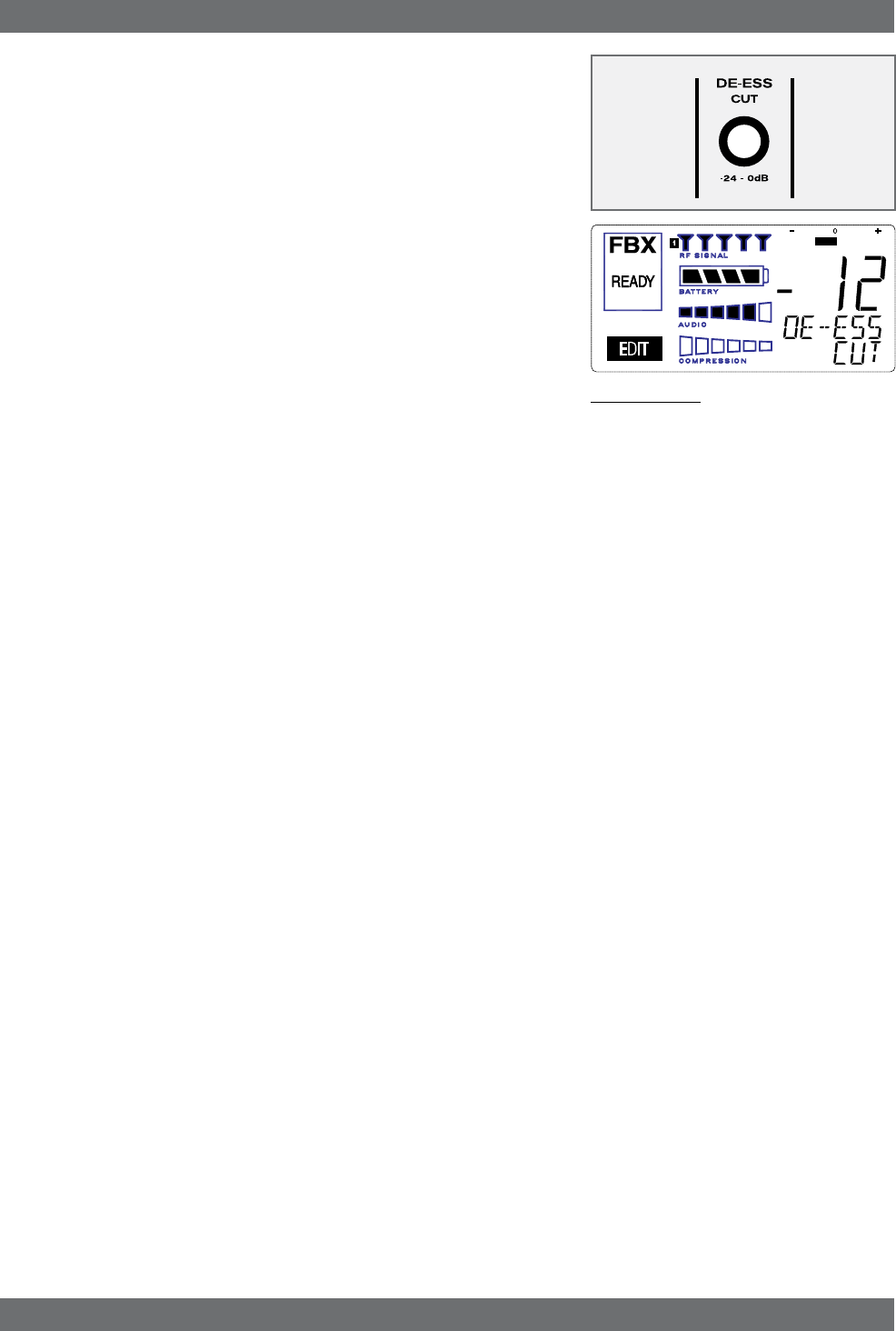
9.3. Using the De-esser
Using the Sabine De-esser is simplicity itself. Turning the knob labeled “DE-
ESS CUT” counterclockwise will increase the amount of sibilance reduction, by
increasing the maximum depth of the shelving filter. The maximum allowable
cut is 24 dB.
Fig. 9a: De-esser
De-esser
34
Sabine Smart Spectrum® Wireless
© 2009 Sabine, Inc.
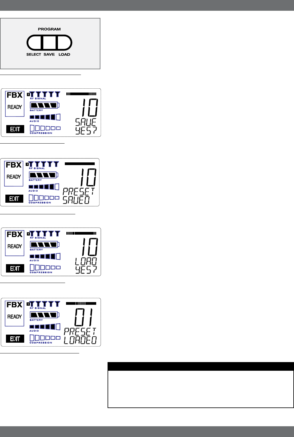
Fig. 10e: Program PRESET LOADED
10. PROGRAM SAVE & RECALL
Most wireless microphone systems provide control of one or two settings (RF
channel and maybe gain). With so little to remember, the ability to save and recall
system settings has not been necessary. With the Sabine Smart Spectrum®
series, however, you get a very sophisticated processor with a variety of adjust-
able parameters. The ability to save and recall your carefully programmed setups
can be a tremendous time-saver. Your Sabine receiver allows you to store and
recall up to 10 different presets.
10.1. Saving a Preset
To save a program, press the SELECT button. The last preset used (numbered
01 - 10) will be shown in the LCD Display (see Fig. 10b). If you want to replace
an existing program, press SELECT until you reach that program’s number. Then
press the SAVE button. The function display will show “YES?”. If you are ready to
save, immediately press the SAVE button again, and your settings will be saved
to that program number. The message PRESET SAVED will be shown for four
seconds in the text display to confirm this action, as the LCD Display continues
to show the number (01-10) of the preset (see Fig. 10c). After four seconds, the
LCD Display will revert to an indication of the RF channel.
10.2. Loading a Preset
Loading a program is just as easy. Press SELECT until you locate the program
number you wish to load. Press LOAD. The function display will show “LOAD
YES?” (see Fig. 10d). Immediately press the LOAD button again and your new
program, including all the parameters, will be loaded for that channel. The mes-
sage PRESET LOADED will appear in confirmation (see Fig. 10e).
10.3. Naming a Preset
Presets, channels and receivers can be named using the Sabine True Mobility
Remote Software. Refer to Section 13 for details.
10.4. Power Off Memory
The receiver retains in memory all settings in effect at the time of being powered
off, and returns to those settings when powered on.
Program Save & Recall
Fig. 10a: Program Front Panel Buttons
Fig. 10b: Program SAVE YES?
Fig. 10d: Program LOAD YES?
Fig. 10c: Program PRESET SAVED
PRESET NOTES
1. Preset 01 is the System Default (SYSDEF on the front panel) and you cannot
save a preset here. Load this setting when you want to return the receiver to the
factory default settings.
2. Preset names will appear on the LCD only after you name the preset using the
remote control software.

35 Sabine Smart Spectrum® Wireless
LIT-SWM6-7000-OG-EN-090215.indd - rr
© 2009 Sabine, Inc.
11. MULTIPLE SYSTEMS OPERATION
11.1. Overview
In many circumstances a single wireless microphone system is all that will be
in use at any one time. Larger applications (church, concert hall, theater stage,
conference room, etc), however, can often require a large array of wireless mi-
crophones, all demanding flawless uninterrupted simultaneous operation.
Multiple system operation presents at least two important operational challenges:
interference among transmission channels, and setup complexity. Sabine Smart
Spectrum provides powerful solutions to both, particularly the interference
problems associated with two or more RF channels at work at the same time,
at the same location.
11.1.1. Multiple System Interference
Sabine Wireless addresses multiple system interference with two strategies.
First, greater available bandwidth in the 2.4 GHz and 915 MHz ranges means
more channels can occupy the band, i.e., the expanded range can be divided
into a greater number of separate transmission/reception bands. Second,
with Smart Spectrum transmission and reception, channels are more tolerant
of interference. The net result is that Sabine Wirelss offers the potential for
many more simultaneous transmission channels than conventional UHF or
VHF systems.
While such performance benefits are one of the major advantages of the
SWM, more systems working at the same time leads to a greater potential for
complexity. Fortunately, the SWM6000 and 7000 also offer tools to simplify
setup and operation.
11.1.2. Setup Complexity
Multiple wireless systems in a large installation are of course more compli-
cated than a single transmitter/receiver. More space is needed, and the sheer
quantity of transmitters and receivers that may be in use at a single installation
can prove difficult to manage. The SWM series helps manage such potential
complexity with four strategies and/or system accessories:
1. First, the dual channel receivers (SW72 and SW62) receivers offer a 50%
space-saving advantage with 2-channel receivers that occupy the same 1U
space as single channel receivers. Each channel in a 2-channel system
shares the true diversity operation of the two antennas connected to the
single receiver chassis.
2. Second, the optional SWA6SS (six-system antenna distribution amplifier)
greatly reduces the complexities of multiple receiver antenna deployment.
Since each receiver has two (diversity) antennas, which can be mounted
on either the rear or front panel, multiple receivers at one location can
potentially create a forest of antennas protruding from the front or back
of a rack. The SWA6SS Antenna Distributor reduces the number of
antennas to as few as 1/6 what would otherwise be needed. An added
important advantage of using the SWA6SS is its distributed signal boost
provided to all the antenna outputs, delivered while maintaining diversity
in all attached reception channels.
3. Third, large installations often entail long distances from transmitters
to receivers, or the presence of obstacles (walls, for example) in the
transmission path that can interfere with clear reception. While the
SWM Series series are designed to minimize these kinds of problems
without accessories, the SWASS-EXT (set of two extension antennas,
shown in figure 12b on page 38) may prove helpful or even necessary
in some situations. In addition to providing remote and/or desirable low
profile positioning with improved reception, the SWASS-EXT also adds
significant gain for even more reliable system performance. The Exten-
sion Antenna and Distribution Amplifier components are also designed to
operate in tandem, with the Extension Antenna plugged directly into the
amp, which can then feed (via cable) the antenna inputs of 6 receivers.
A combination of 2-channel receivers, a set (2 pieces) of SWASS-EXT,
and one SWA6SS, would reduce the antenna clutter of 12 transmission
Multiple Systems Operation

36
Sabine Smart Spectrum® Wireless
© 2009 Sabine, Inc.
channels to a single pair of extension antennas. See Section 12 for more
information about setup and use of the SWASS-EXT.
4. Fourth, software control for the ND series receivers allows up to 70 re-
ceiver channels to be controlled from a single computer. This quick and
powerful control methodology means you can monitor and change trans-
mission channels, mic modeling, compression and de-essing — in short,
all front panel controls — from a remote laptop or desktop. In addition to
simplifying multiple unit operation with remote front panel controls, the
remote software provides additional features and functions not available
from front panel control. See Section 13 for more information about setup
and use of the Remote Software.
11.2. Antenna Distribution Amplifier
Sabine’s optional accessory SWA6SS Antenna Distribution Amplifier is ideal for
simplifying antenna set up when multiple receivers are used, by using a single
pair of antennas to replace pairs for up to 6 different receivers. Standard equip-
ment packed with each Antenna Distributor includes an AC power cable, and 6
pairs of 1-meter long jumper cables (RG-58 AU foam core) for connecting the
Antenna Distributor to receivers (2 cables provide true diversity reception to
each receiver).
For best results, the Antenna Distribution Amplifier should be positioned close
enough to the receivers to minimize cable runs. In most applications, you can
use the standard Sabine 2.4 GHz or 915 MHz antennas supplied with any of
the receivers to connect to the terminals on the Antenna Distributor, and then
connect (in matching pairs) the jumpers to all your receiver antenna connections
(up to 6 receivers, 1 pair per receiver).
Care should be exercised when using longer cables, due to possible transmis-
sion signal loss (approximately 1.7 dB/meter). Using the “rule-of-thumb” that a
signal loss no greater than 6 dB will prove acceptable in many circumstances,
you may be able to use RG-58 cable up to 3 meters or so in length. However,
a better strategy than moving the Antenna Distributor to a better position, and
risking excessive transmission loss back to the receivers or requiring an up-
grade to more expensive cable, is to utilize a pair of Sabine Extension Antennas
(SWASS-EXT). These will connect to the antenna inputs of the Antenna Distri-
bution Amplifier, and offer increased range, better rear-source RF rejection, an
expanded 135 degree forward sensitivity, flexible mounting options, and signal
boost (see Section 12).
For more details regarding specifications and operation of the SWA6SS An-
tenna Distribution Amplifier, please refer to the operating guide included with
that product.
Multiple Systems Operation
37 Sabine Smart Spectrum® Wireless
LIT-SWM6-7000-OG-EN-090215.indd - rr
© 2009 Sabine, Inc.
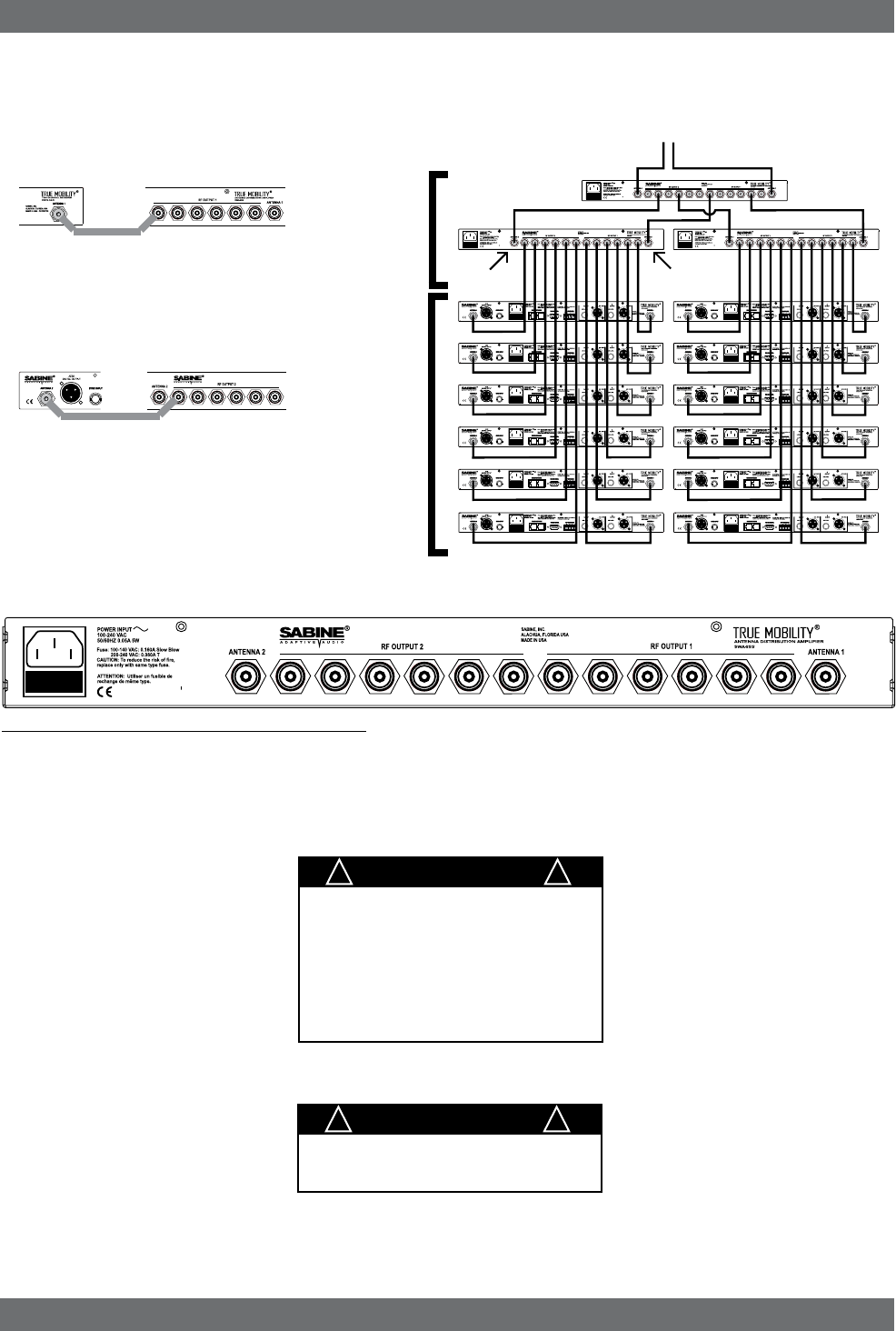
11.3. Antenna Distribution Amplifier Connection
Multiple Systems Operation
Fig. 12a: SWA6SS Antenna Distribution Amp Back Panel
To Extension Anten-
nas
Antenna 1
RF Output 2 RF Output 1
SWA6SS
Antenna
Distribution
Amplifiers
SWM
Series
Receivers
Antenna 2
1
3
2
IMPORTANT
Antenna Cabling Impedence
must be 50 Ohm.
! !
IMPORTANT
Active Electronics Antenna
Sabine wireless receivers provide
antennas with active electronics. The
inputs to the receiver & antenna dis-
tributor amplifier have phantom ower
available for this purpose.
DO NOT SHORT TO GROUND
! !
Connect receiver Antenna 1 input to any RF
Output 1 connector on the SWA6SS.
.
Connect any receiver Antenna 2 to any RF
Output 2 connector on the SWA6SS.
Continue with remaining receivers
Antenna Distribution
Amplifier (SWA6SS)
Receiver
Antenna Distribution
Amplifier (SWA6SS)
Receiver
38
Sabine Smart Spectrum® Wireless
© 2009 Sabine, Inc.
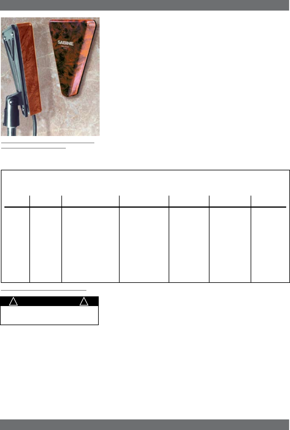
12. EXTENSION ANTENNAS
12.1. Overview
Sabine’s receivers are designed for easy interface with Sabine’s SWASS-EXT
Extension Antenna Kit (figure 12b). This triangular, attractive wood-grained unit is
designed to mount easily and unobtrusively on a wall (allowing either a through-
the-wall or out-the-bottom connection), or (by threading) atop a microphone stand
for a more portable or temporary positioning. Each package contains 2 Exten-
sion Antennas, all necessary mounting hardware (screws and mic stand thread
connectors) and both right-angle and straight connectors for mating with RG-58
cable (for connections to a receiver or Antenna Distribution Amplifier).
12.2. Antenna Cabling & Cable Loss
While an extension antenna affords the opportunity to increase the distance from
transmitter to receiver, there is a loss of signal in the interconnecting cable that
limits that distance. The maximum connection length is determined by the type
of cable used, and the degree of signal attenuation acceptable.
Sabine’s Active Extension Antenna allows for a cost-effective way of boosting
signal levels due to its built-in active switchable (+22 or +44) signal boost. In the
case of low-cost RG-58 cable, adding an SWASS-EXT to your setup increases
the acceptable maximum cable run by more than 4 times, to 14 meters. With
RG-8 cable, the maximum length is extended to 88 meters.
Extension Antennas
Fig. 12b SWASS-EXT Mic-stand mount and
wall-mount extension antennas
RG58 9203 Polyethylene #20 Stranded -16.29 14 TNC
RG58/AU 9311 Foam Polyethylene #20 Stranded -11.10 20 TNC
RG212/U 9861 Polyethylene #15.5 solid, -6.11 36 N
Silver Plated
RG8/U 9913 Semi-solid Polyethylene #10 Solid -2.50 88 N
RG142 83242 Teflon #18 Solid, -6.54 34 TNC
Silver Plated
Coaxial Cable Attenuation Table - 2.4 GHz
Fig. 12c Coaxial Cable Attenuation Table
10 Meter
Attenuation
(dB)
Maximum Prac-
tical
Distance Using
SWASS-EXT
set for +22 dB
boost (meters)
Cable
Type Belden # Insulation
Center Con-
ductor
Connector
Type
IMPORTANT
Antenna Cabling Impedance
must be 50 Ohm.
! !
Power for the Extension Antenna is delivered from any Sabine SWM series
receiver or SWA6SS Antenna Distribution Amplifier (see Section 11).
An additional advantage of using Sabine’s SWASS-EXT Extension Antenna
stems from its more focused, directional nature. Sabine receiver’s coaxial dipole
antennas (standard equipment that mount directly on the front or rear panels of
the receiver or SWA6SS) are more omni directional in nature. In contrast, the
Sabine’s Extension Antenna is sensitive to RF reception in a 135-degree arc in
front of its mounted position. It extends sensitivity to the front and off-axis side
locations as it increases rear RF rejection.
NOTE: The higher boost level (+44 dB) is only recommended for very long cable
runs - at least 50 meters, or you have more than a 12 dB of cable loss. Using
this setting without that much cable loss can cause a signal overload and poor
RF performance.
The multiple functions (relocation of antenna, boost of signal, directional sensitiv-
ity) of Sabine’s Extension Antenna mean there are many applications in which
its addition to your system can greatly enhance performance. Here’s a short list
of such applications and operating instructions:
Need 915 MHz chart here, too.

39 Sabine Smart Spectrum® Wireless
LIT-SWM6-7000-OG-EN-090215.indd - rr
© 2009 Sabine, Inc.
1. Antenna Repositioning. Provides solutions when receiver placement
options are limited or challenging. Sabine’s Extension Antenna’s multiple
mounting options allow higher placement (wall mount or microphone stand
mount).
2. Barriers interrupting transmission. Anytime a barrier interferes with
transmission and reception, Sabine’s SWASS-EXT can be mounted on the
transmitter side of the barrier with cable connections made on the receiver
side. Perhaps the most common situation of this nature would arise when
receiver and transmitter are located in separate rooms.
3. Expanded or directional sensitivity required. Sabine’s Extension Antenna
picks up in a 135-degree arc, focused towards the front. Reception in this
arc is enhanced.
4. Rear RF rejection required. Because Sabine’s Extension Antenna is less
sensitive to signals received from the rear, it can be positioned to reject any
such directional RF interference.
5. Extended operational range. Given a potential maximum cable length of
almost 90 meters from Extension Antenna to receiver, Sabine’s SWASS-
EXT allows more options for extending the distance between transmitter
and receiver. (The typical range of Sabine Wireless without the Extension
Antenna is already 100 meters in typical circumstances). Consider that RF
signal strength through the air is diminished by the square of the distance
(twice as far away = ¼ the signal strength), while signal loss through cable
is (roughly) inversely proportional (twice as far away = ½ the signal). That
means you can use an extension antenna to replace transmission-through-air
with transmission-through-cable, to help minimize signal loss.
6. Placing extension antennas. The assymetrical pattern of each antenna
helps reduce the chance for a null spot in your room. You may use either
antenna on the left or right side of your performance space. When you mount
the extension antennas on a stand or on a wall, make sure the short end of
the triangle is up.
7. In order for the system to be effective, both extension antennas should be
in a good pickup position at all times but separated by about ten or fifteen
feet if the antennas are within 100 or so feet.
8. If you put the antennas too far apart, i.e., at opposite ends of the room, or
in separate rooms, to improve coverage, diversity is defeated and you will
get dropouts. In other words, diversity is more important that coverage. If
you mount the extension antennas in the ceiling, the antennas metallic
backplane must be orientated parallel to the floor and the antennas must not
be blocked by pillars, lights or similar obstructions. Aim the hole in the plastic
cover toward the podium.
9. Do not daisy-chain extension antennas together in series. Receivers and
the antenna distribution amp are only designed to use one left and one right
antenna.
10. Extension Antenna Cables: Use coax cable to connect the extension
antennas to the receiver or to the ADA. See the chart on the previous page
for cable specifications. Use the SWATNC-N step-down cable to connect
thicker RG8 cables to the extension antenna.
11. The SWASS-EXT extension antennas add either 22 or 44 dB signal strength
to overcome cable loss. Bad crimp connections are a common cause of
dropouts. Check them carefully!
Extension Antennas
IMPORTANT
Active Electronics Antenna
Sabine wireless receivers provide
antennas with active electronics. The
inputs to the receiver & antenna dis-
tributor amplifier have phantom power
available for this purpose.
The red LED on the inside of the an-
tenna cover indicates phantom power
(3V) is good.
DO NOT SHORT TO GROUND
! !
The SWASS-EXT features:
• Wall or mic-stand mount
• Straight and right angle TNC
connectors
• 135 degree reception pat-
tern
• +22 or +44 dB boost in RF
• Matched pairs
• Wood-tone finish
• Phantom-powered from either
the receiver or the distribution

40
Sabine Smart Spectrum® Wireless
© 2009 Sabine, Inc.
13. REMOTE CONTROL OPERATION
13.1. Overview
In many circumstances you will adjust and control your Sabine wireless micro-
phone system using the front panel controls, as outlined in previous sections of
this operating guide. In circumstances where an enhanced level of control over
a single receiver is desired, or to enable simultaneous computer-based control
of multiple receivers, you will need to install (on either a laptop or desktop com-
puter) the free Sabine SWM Remote Control Software included with your system.
Only receivers may be remotely controlled; handheld and belt pack transmitters
cannot be remotely controlled.
For online instructions for any function in the software, you may also refer to
the Help menu.
13.1.1. Single vs. Multiple Receiver Control
All series receivers have an RS-232 9-pin serial COMM Port and a USB port.
Thus, any single receiver can be controlled remotely. Control over multiple receiv-
ers from a single computer is possible only with ND-series receivers (SW62 and
72-NDR). These units have additional RS-485 network connections (RJ-45 jacks)
for daisy-chain connection from one receiver to the next. Up to 35 receivers (70
transmission channels if all receivers are 2-channel) may be connected in this
network, all under the control of a single computer. Single- and dual-channel
receivers can be mixed in the same network. The first receiver in such a network
can be connected to the computer via an RS-232 9-pin serial cable or USB cable.
The remaining units connect via an RS-485 cable.
NOTE: It is not possible to upgrade/retrofit a standard receiver to make it an
ND-series unit.
13.1.2 Features & Controls Added Software
All front panel controls and displays are duplicated in the software. In addition,
a deeper level of software control over receiver operation is enabled. These
new controls are complete and independent for each transmission/reception
channel, meaning there are two sets of controls for dual channel receivers.
These controls and displays include:
• Parametric filter access and control. FBX filters can be changed to
parametric filters, and their width, depth, and frequency can be adjusted.
Changes can be made at any time, both before and after FBX filters have
been set. Parametric and FBX filters can be mixed in any combination,
totaling 10 for each receiver channel.
• Adjustable FBX parameter control. Maximum depth of FBX filters can
be adjusted globally; filter width can be adjusted globally or individually.
Two controls, Sensitivity and Persistence, can be tweaked to tailor the
operation of automatic FBX filter placement to match the audio program.
Proper settings will optimize the balance between false filtering and de-
layed response to feedback (the factory default settings should operate
excellently in the vast majority of conditions and may never need to be
changed).
• Control over balance of FBX Fixed and Dynamic filters. Any FBX
filter can be set to be either fixed or dynamic.
• Adjustable high and low cut filters. (Software only) High Cut Filter, user
controllable between 3 KHz and 20 KHz, 12 dB/octave roll-off; Low Cut
Filter user controllable between 20 Hz and 1 KHz, 12 dB/octave roll-off.
• Additional compressor controls. Aside from adjustments for ratio,
threshold, and attack (which duplicate front panel controls), the Remote
Software provides control of compressor release time and knee. The
effect of compression on the output signal as a function of input signal
strength and parameter settings is displayed in Sabine’s unique dynamic
ColorComp graph, in addition to the traditional opposing-meter indica-
tors.
Remote Control Operation
NOTE: Only -NDR receivers have
a USB port. You can use a USB to
RS-232 9-pin adaptor for the standard
units if you need to use USB. Go to
Sabine.com for a list of suggested
adapters.
Is this still true?

41 Sabine Smart Spectrum® Wireless
LIT-SWM6-7000-OG-EN-090215.indd - rr
© 2009 Sabine, Inc.
• RF Scan and Report, which measures strength for each of the 70 trans-
mission channels, and displays a hierarchical ordering of the clearest,
strongest channels to use during system setup and operation. You can
print a copy of the scan results.
• Additional memory options. In addition to saving presets in receiver
memory, channel configuration settings can be saved to and recalled from
disc or hard drive. All parameter settings made with the remote control,
including adjustments that are not accessible from front panel controls
(e.g., compressor knee and release), are saved with presets. All software
settings stored for each of the 10 presets, including settings not accessible
from the front panel, will be loaded whether presets are recalled by remote
control or from the front panel. Note that all settings made in Off-line/Edit
mode can be saved and applied in online operation.
• Ability to print a report of all parameter settings, creating hard copy
documentation.
• A receiver channel output mute button.
• The ability to custom name each RF channel and receiver. This name
will be displayed in the software only.
• Display of important transmitter status information. In addition to
duplicating the battery charge status, battery warning message, and
transmitter on/off/mute status from the front panel display, the Remote
Software displays the number of hours the battery has been in use, the
frequency midpoint (in GHz) of the transmission channel chosen, the
transmitter pad and low cut filter settings, and a warning indication in the
case of low RF signal strength. For handheld transmitters, the software
display also shows the type of mic capsule in use.
• Improved and expanded operational displays. In addition to organizing
all front panel displays on a single computer screen, the Remote Software
also displays the exact frequency, width, and depth of FBX filters. The
frequency response curve resulting from combined filter settings (includ-
ing FBX, parametric, and high and low cut) is graphically displayed in the
software. Frequency response changes imposed by choosing various
microphone models are also shown.
• Customizable front panel lock settings. Software control allows you
to program selective access to front panel controls to be made available
once the Remote Control is disconnected. Customizable front panel lock
settings are saved and recalled as part of each receiver’s settings. All
software-only accessible settings are saved with presets. Careful program-
ming enables some powerful operational features — for example, locking
Program Save but enabling other front panel controls (including Program
Load) will let front panel users update settings temporarily, yet reload the
original settings at the push of a button. Such a temporary adjustment
would not permanently alter a setup designed to work in most situations,
but would allow tweaking to address unusual situations.
Remote Control Operation
WARNING:
BEFORE DISCONNECTING RECEIVER FROM COMPUTER
Quit all SWM Software functions and close software BEFORE disconnecting the receiver connection to you computer.
Failure to do this may cause the receiver to lock up. In case of receiver lock up, restart receiver.
42
Sabine Smart Spectrum® Wireless
© 2009 Sabine, Inc.
13.1.3. Software Multiple Unit Control
The true extent of the power of the SWM Remote Software is realized when it
is used to control multiple wireless receivers. When ND-series receivers are
connected in a network, the additional controls offered by the Remote Software
over the entire system include:
• Simultaneous multiple channel/system monitoring. The Remote Soft-
ware “All Channel View” (figure 13h) shows all important status conditions
for up to 70 transmission channels. Color-coded warnings and alerts draw
attention to potential problems.
• Detailed, quick access to a single set of controls. The “Command
View” (figure 13c) displays comprehensive information about a single
selected RF channel, and easy adjustment of all its controls. Channels
are selected by clicking the appropriate All Channel View button. (NOTE:
Each channel display in the All Channel View also allows quick access
to parameter adjustments, by using the right mouse button to popup a
parameter control menu.)
• Quick, interactive control of wireless network channels. All or selected
parameter settings for a given channel can be copied to one or more ad-
ditional channels, using the Copy Parameters option.
13.2. Software Installation
13.2.1. Requirements & Recommendations
• PC Minimum Requirements: Pentium 266 MHZ CPU or AMD Duron
CPU; 128 Megabytes of RAM; 20 Megabytes free space on hard drive;
Windows 95 or higher.
• PC Recommended Requirements: Pentium 1.0 GHZ CPU or AMD
Athlon CPU; 512 Megabytes of RAM; 20 Megabytes free space on hard
drive; Windows 2000 or XP.
• SVGA or greater resolution graphic card and monitor. Recommended
minimum monitor resolution: 1024 x 768 pixels (or 800 x 600 pixels for 15
inch monitors). Select “small fonts” and 16 bit color as defaults for monitor
display. Windows XP users select 96 dpi screen settings.
• USB or Serial COMM Port.
13.2.2. Connections
There are three types of connections that are used in a remote controlled one-
or two-channel Sabine system:
• Serial port (RS-232 9-pin): Use this to connect to a single receiver, or
the first receiver in a network (multiple receivers). Be sure to use a cable
with standard 9-pin D-connectors (male on one end, female on the other)
that is a “serial,” not a “null modem” cable.
• USB: Use this to connect to a single receiver, or the first receiver in a
network (multiple receivers).
NOTE: Some receivers may not have a USB port. In this case, simply use
a USB to RS-232 9-pin adaptor. Go to Sabine.com for a list of suggested
adapters.
• Network (multiple -ND series receivers):
1. Connect the first receiver in your network to the PC using a USB cable
or an RS-232 Serial Cable (not supplied).
2. Connect all other receivers as a chain using RS-485 (or standard
Ethernet) cables. There are two such jacks on the back of all ND-series
receivers. Either jack can connect to another receiver either “upstream”
or “downstream” from the computer remote control. As signals travel in
both directions (from computer to receiver and back), it is not necessary
to connect the last receiver in a network back to the computer (you do
not need to make a “loop”).
Remote Control Operation
USB DRIVERS
Your USB-enabled receiver requires ver-
sion 2.0 or above software. Installing this
software also installs the necessary USB
drivers onto your computer. If at any time
you need to re-install USB drivers, use the
software CD supplied with your receiver, or
download them from Sabine.com.
NETWORK
CABLE CONNECTIONS
Connect the first receiver of a network
using a USB or RS-232 9-pin connection.
All subsequent receivers connect to each
other via RS-485 connection.
UP: All but the first
receiver connected to
a network.
DOWN: First receiver
connected to the net-
work.
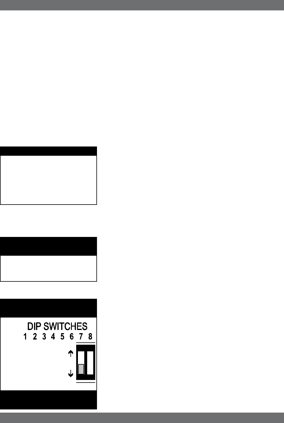
NETWORK
DIP SWITCH SETTINGS
See page 55 for a chart of all
DIP switch settings.
43 Sabine Smart Spectrum® Wireless
LIT-SWM6-7000-OG-EN-090215.indd - rr
© 2009 Sabine, Inc.
3. IMPORTANT: Set dip switch #7 on the back of the first receiver to the
“OFF” (down) position (default). Set dip switch #7 on all other networked
receivers to the “ON” (up) position.
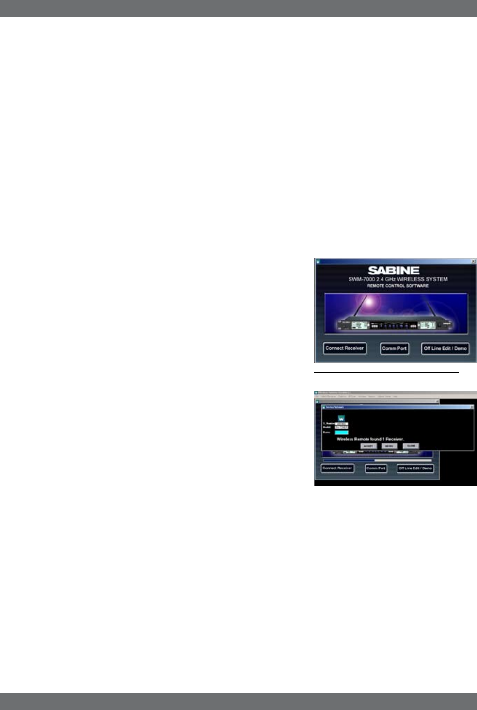
4. When all cable connections have been made, open the SWM Remote
Control Software program on your PC. The software will find all the re-
ceivers in the network and show them in a dialog box (receiver sequence
can be reordered). Click “Accept” to control the network. NOTE: Up to 35
2-channel (or 1-channel, or any combination thereof) receivers – totalling
up to 70 transmission channels – can be connected in a single network
to a single PC.
13.2.3. Installing the Software
Follow these simple instructions for installing the Sabine SWM Remote Soft-
ware on your computer:
1. Insert the Sabine software CD into your PC’s CD ROM drive and wait a
few seconds for the auto-start software installer to open.
2. Select the SWM Remote Control Software installation icon and follow the
instructions given in the dialog boxes that appear. NOTE: For best results,
allow the installation program to install the software within the default
directories.
13.3. Launching the software
Launching the software produces the Startup Screen (Fig. 13a).
13.3.1. Off-Line Edit/Demo
Clicking the right button (“Off-Line Edit/Demo”) will open the main software
screen regardless of whether any SWM receivers are connected. The software
functions in Off-Line mode are completely programmable, and may be saved
and downloaded to a connected receiver at a later time. Display settings
(e.g., level, compression, transmitter settings) which are dependent on the
presence of actual signal are simulated, for demonstration only. You may turn
the simulated displays on or off using the OPTIONS menu.
13.3.2. Connecting Receivers.
Comm Port: Select the Comm port you are using to connect the receiver(s).
Connect Receiver: Select this and the software will poll the bus on the desig-
nated COMM Port to detect connected, powered-on receivers. If no receivers
are detected, you may change the designated COMM Port by clicking the appro-
priate button. If this also proves ineffective, check your cables and connections,
and make sure the connected receivers are powered on. In very rare instances
you may need to reset your COMM Port settings on your computer.
Once polling is completed, the software will display all the receivers detected,
in sequence, and the model of each receiver (ND series or standard, 1 or 2-
channel). (See figure 13b for a sample opening display)
You may re-order the receivers here. When multiple receivers are connected a
numeric field appears above each one. Enter the new order values and select
“Re-Order.” You may also verify your receiver selections by clicking on the icons
above each receiver. The corresponding receiver’s front panel will flash.
Once you confirm that the information reported is correct, choose “Accept” to
proceed to the main screen, where you may begin remote control operation.
Fig. 13a Control Software Startup window
Remote Control Operation
Fig. 13b - Connection Screen
How many channels for 6000?