SAF Tehnika AS 58F2DMX LTE-U Transmitter User Manual CFIP PhoeniX 5 8 TD EN V 1 1
SAF Tehnika A/S LTE-U Transmitter CFIP PhoeniX 5 8 TD EN V 1 1
Contents
- 1. User Manual 1
- 2. User Manual
User Manual

The CFIP Series Full Outdoor Unit Technical Description and Configuration Guide • Rev. 1.13
© SAF Tehnika A/S 2015 1
CFIP PhoeniX Series
TDM/IP Split Mount System
Technical Description & Configuration Guide
SAF Tehnika JSC 2015
CFIP PhoeniX 5.8 Technical Description and Configuration Guide • Rev. 1.0 •
© SAF Tehnika JSC 2015
2
Proprietary notice
The information presented in this guide is the property of SAF Tehnika, JSC. No part of this
document may be reproduced or transmitted without proper permission from SAF Tehnika, JSC.
The specifications or information contained in this document are subject to change without notice
due to continuing introduction of design improvements. If there is any conflict between this
document and compliance statements, the latter will supersede this document.
SAF Tehnika, JSC has no liability for typing errors in this document or damages of any kind that
result from the use of this document.
To get up to date information about accessories and their availability, please contact sales
representative.
FODU does not contain serviceable parts. Warranty will not be applicable in
the event FODU has been hermetically unsealed.
SAF Tehnika, JSC is not responsible for any radio or TV interference caused by
unauthorized modifications to this equipment. Such modifications could void
the user's authority to operate the equipment.
This device complies with part 15 of the FCC Rules. Operation is subject to the following two
conditions: (1) This device may not cause harmful interference, and (2) this device must accept any
interference received, including interference that may cause undesired operation.
Note: This equipment has been tested and found to comply with the limits for a Class B digital
device, pursuant to part 15 of the FCC Rules. These limits are designed to provide reasonable
protection against harmful interference in a residential installation. This equipment generates, uses
and can radiate radio frequency energy and, if not installed and used in accordance with the
instructions, may cause harmful interference to radio communications. However, there is no
guarantee that interference will not occur in a particular installation. If this equipment does cause
harmful interference to radio or television reception, which can be determined by turning the
equipment off and on, the user is encouraged to try to correct the interference by one or more of
the following measures:
Reorient or relocate the receiving antenna.
Increase the separation between the equipment and receiver.
Connect the equipment into an outlet on a circuit different from that to which the
receiver is connected.
Consult the dealer or an experienced radio/TV technician for help.
This device complies with Industry Canada licence-exempt RSS standard(s). Operation is subject to
the following two conditions: (1) this device may not cause interference, and (2) this device must
accept any interference, including interference that may cause undesired operation of the device.
Le présent appareil est conforme aux CNR d'Industrie Canada applicables aux appareils radio
exempts de licence. L'exploitation est autorisée aux deux conditions suivantes : (1) l'appareil ne
doit pas produire de brouillage, et (2) l'utilisateur de l'appareil doit accepter tout brouillage
radioélectrique subi, même si le brouillage est susceptible d'en compromettre le fonctionnement.
Copyright Notice
Copyright © 2015 SAF Tehnika, JSC. All rights reserved.

CFIP PhoeniX 5.8 Technical Description and Configuration Guide • Rev. 1.0 •
© SAF Tehnika JSC 2015
3
Table of Contents
1 Overview .............................................................................................................................. 4
1.1 CFIP PhoeniX TDM/IP split mount system ................................................................................ 4
1.2 CFIP PhoeniX feature Summary ................................................................................................ 5
1.2.1 Main Features .................................................................................................................................... 5
1.2.2 ODU mechanical features .................................................................................................................. 5
1.3 CFIP PhoeniX ODU Parameters ................................................................................................. 5
1.4 Application Examples ............................................................................................................... 5
1.4.1 CFIP PhoeniX 1+0 configuration ......................................................................................................... 5
1.5 Microwave Radiation ......................................................................................................... 8
1.6 Technical specification.............................................................................................................. 6
1.7 Cable Requirements .................................................................................................................. 6
1.8 Labelling ................................................................................................................................... 7
2 RSSI Port ......................................................................................................................... 10
3 Available Accessories .................................................................................................... 11
3.1 Other Available Accessories.................................................................................................... 11
4 SAF Tehnika JSC Contacts ..................................................................................................... 12

CFIP PhoeniX 5.8 Technical Description and Configuration Guide • Rev. 1.0 •
© SAF Tehnika JSC 2015
4
Proprietary notice
The information presented in this guide is the property of SAF Tehnika, JSC. No part of this document
may be reproduced or transmitted without proper permission from SAF Tehnika, JSC.
The specifications or information contained in this document are subject to change without notice
due to continuing introduction of design improvements. If there is any conflict between this
document and compliance statements, the latter will supersede this document.
SAF Tehnika, JSC has no liability for typing errors in this document or damages of any kind that result
from the use of this document.
To get up to date information about accessories and their availability, please contact sales
representative.
Note: FODU/ODU does not contain serviceable parts. Warranty will not be applicable in the
event FODU/ODU has been hermetically unsealed.
Note: SAF Tehnika, JSC is not responsible for any radio or TV interference caused by unauthorized
modifications to this equipment. Such modifications could void the user's authority to operate the
equipment.
Copyright Notice
Copyright © 2015 SAF Tehnika, JSC. All rights reserved.
1 Overview
This document briefly describes the CFIP PhoeniX series TDM/IP split mount system (IDU+ODU)
covering the built-in management system, configuration functionality, hardware features, etc.
1.1 CFIP PhoeniX TDM/IP split mount system
CFIP product family is the new next generation product line which is targeting growing demands for
data transmission over microwave radio.
As a result the primary traffic interface for CFIP split mount system is Gigabit Ethernet. As CFIP is
capable of providing bit rate of up to 363Mbps, it is a great addition to SAF portfolio. CFIP radio and
modem performance allows achieving high system capacity by employing 256-decision states
modulation scheme by user’s choice. Apart from the full system capacity of 363Mbps, it is possible to
configure the radio to any of 3.5, 7, 14, 28, 40 and 56 MHz channels as well as to any of 4QAM, 16QAM,
32QAM, 64QAM, 128QAM and 256QAM modulations, thus providing various capacities to suit
particular needs.
SAF Tehnika has employed most modern design solutions and components to create high performance
split mount system with low power consumption – 33-69W per system.
CFIP is a perfect building block for any modern future proof wireless network, including mobile service
providers, fixed data service operators, enterprise customers, municipal and governmental networks
among others.
CFIP PhoeniX 5.8 Technical Description and Configuration Guide • Rev. 1.0 •
© SAF Tehnika JSC 2015
5
1.2 CFIP PhoeniX feature Summary
1.2.1 Main Features
• Split mount system solution
• Capacity: up to 363 Mbps
• Channel Bandwidth: 3.5 / 7 / 14 / 28 / 40 / 56 MHz
• Modulations: 4QAM / 16QAM / 32QAM / 64QAM / 128QAM / 256QAM
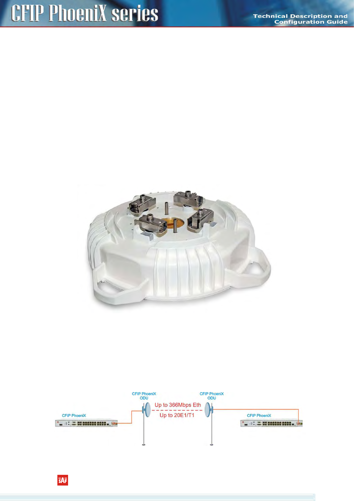
1.2.2 ODU mechanical features
• Compact unit, 285x285x80mm, 3.9kg, antenna adaption backwards compatible with all CFM
and CFQ series units
• 3 handles for user convenience
• Safe and easy to use 4 side locking arrangement
• All connectors on the side of the unit, always at 45° regarding vertical axis for both V and H
polarization
Figure 1.1 CFIP PhoeniX ODU
1.3 Application Examples
1.3.1 CFIP PhoeniX 1+0 configuration
• Basic split-mount 1+0 system with up to 20E1/T1 or up to 363 Mbps Ethernet
Figure 1.2 CFIP PhoeniX 1+0 configuration
1.4
CFIP PhoeniX 5.8 Technical Description and Configuration Guide • Rev. 1.0 •
© SAF Tehnika JSC 2015
6
1.4 Technical specification
CFIP PhoeniX ODU
General
Band 5.8 GHz
Form factor IDU – ODU split-mount
Antenna External
Tx-Rx architecture FDD
RF
Frequency range 5725 – 5850 MHz
Max Tx power + 30 dBm
Max channel bandwidth 30 MHz
Supported modulations QPSK/4QAM, 16QAM, 32QAM, 64QAM, 128QAM, 256QAM
Duplex offset 95MHz
Ports
Antenna N-Type
IF to IDU N-Type
RSSI BNC
Mechanical & Electrical
Operational use Conforms to ETSI EN 300 019 Class 4.1, IP65, NEMA 4X
Temperature Range -27°F to +131°F
Dimensions: HxWxD /
weight 11.3x11.3x3.1 in / 7.7 lb
IF port surge protection Conforms to ETSI EN 301 489-1; EN 61000-4-5; IEC 61000-4-
5
Input DC voltage -40.5V to -57V DC (conforms to ETSI EN 300 132-2)
Max. power
consumption SP: 13-27 W; HP: 21-39 W
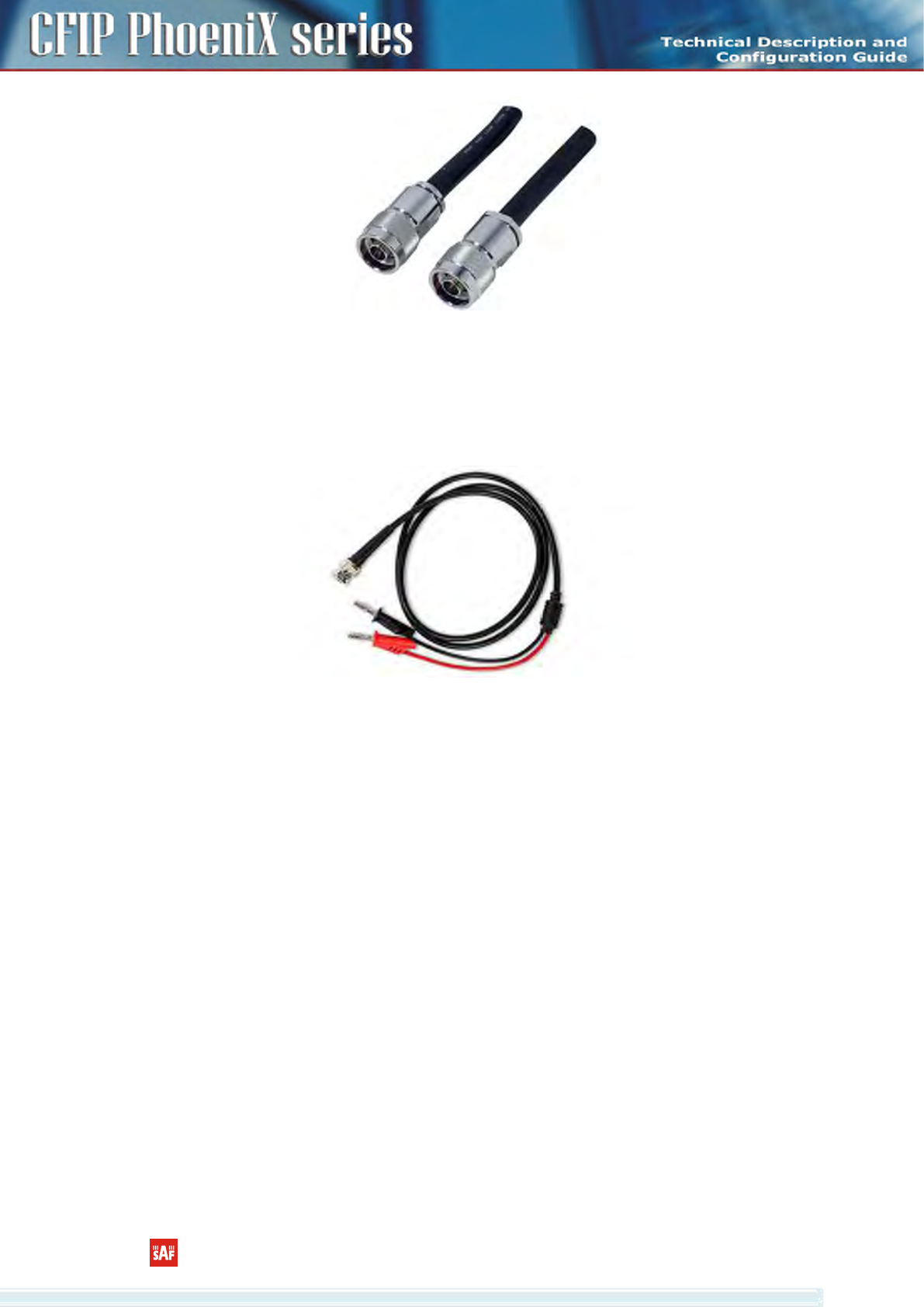
1.5 Cable Requirements
IDU-ODU cable
IDU-ODU cable is a 50 Ω coaxial cable intended to interconnect the Indoor Unit with the Outdoor
Unit. Any type of 50 Ω cable of good quality can be used; the cable should be equipped with N–type
male connectors on each end. There are two N–type male connectors included in each radio unit
delivery that fit RG–213 cables or other cables with a surface diameter of 10 mm. As the attenuation
of the cable is essential particularly at 350 MHz frequency, its usage is restricted, - the attenuation of
the signal should not exceed 20 dB at 350 MHz. Commonly employing RG–213 type coaxial cable, its
length may reach 100 m, LMR–400 type cable may usually reach up to 300 m in length.
CFIP PhoeniX 5.8 Technical Description and Configuration Guide • Rev. 1.0 •
© SAF Tehnika JSC 2015
7
Figure 1.3 CFIP PhoeniX IDU-ODU cable
RSSI BNC
To connect the digital multimeter to the CFIP PhoeniX ODU RSSI port in order to adjust the antenna
alignment, a coaxial cable with BNC connector on one end and appropriate termination on other end
can be used (see example in Figure 1.4).
Figure 1.4 Cable for connecting the voltmeter to the CFIP PhoeniX ODU RSSI port
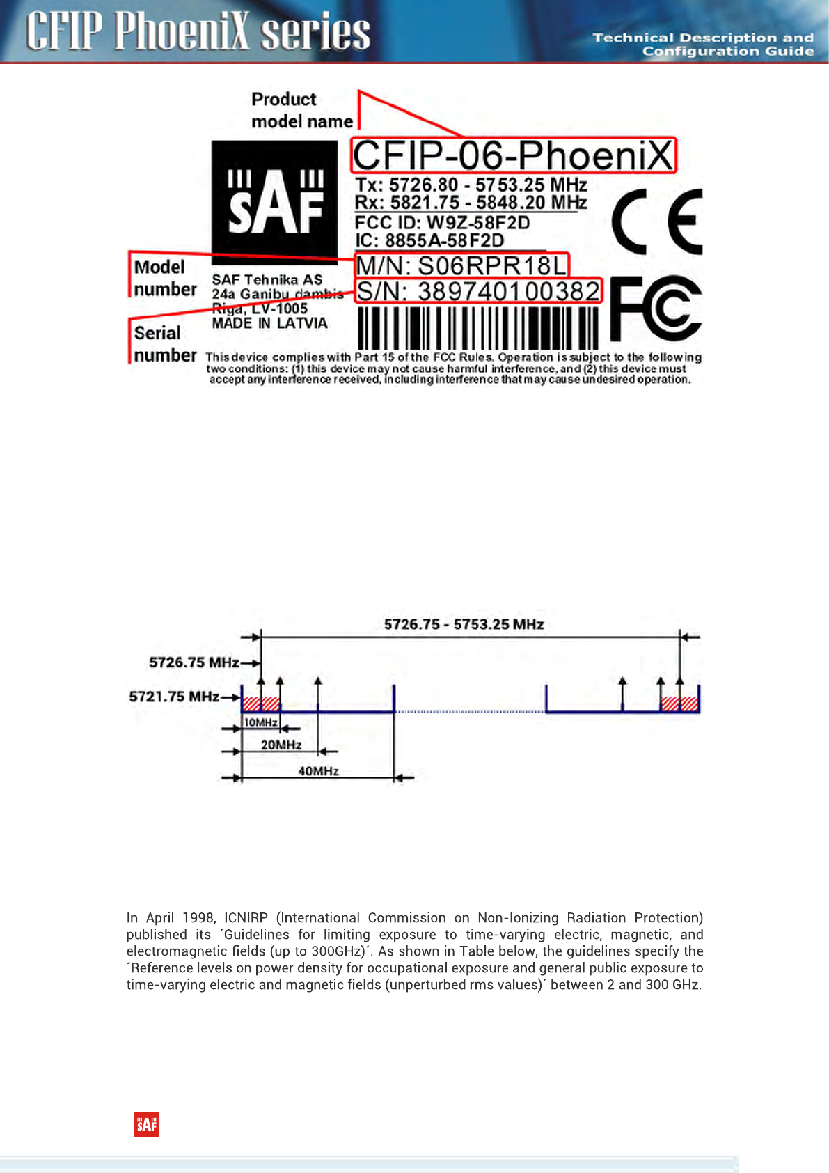
1.6 Labelling
The label contains the following information (see samples in the picture below):
- Model name. The model name example is:
CFIP-06-PhoeniX for 5.8GHz Outdoor Unit (ODU), etc
- Product Number (S06RPR18L): product number contains information of product version
(18), in case of ODU - in which frequency band (06) and band side (L, H) the ODU operates.
Letters A, B, C or D indicate specific subband (if applied).
- Unit Serial Number (389740100382); the serial number uniquely identifies the unit.
CFIP PhoeniX 5.8 Technical Description and Configuration Guide • Rev. 1.0 •
© SAF Tehnika JSC 2015
8
Figure 1.5 Label of the CFIP PhoeniX ODU Low band side, operating in 5.8 GHz band
P/N Translation for CFIP PhoeniX ODU:
- “S” designates CFIP split mount series product;
- “06” designates Frequency range (5.8 GHz) of the Unit;
- “RP” designates high power radio;
- “R” designates ODU operating 10 - 40MHz;
- “18” designates the version number of the Unit;
- “L” designates the band side in which ODU operates (H, L).
Please note that frequency range is set from the central frequency of the first 14 MHz channel to the
central frequency of the last 14 MHz channel (see the Figure 1.6).
Figure 1.6 Frequency range of the low side CFIP PhoeniX 18 GHz ODU
Figure 1.6 explains Tx frequency range of low side CFIP PhoeniX 18 GHz radio.
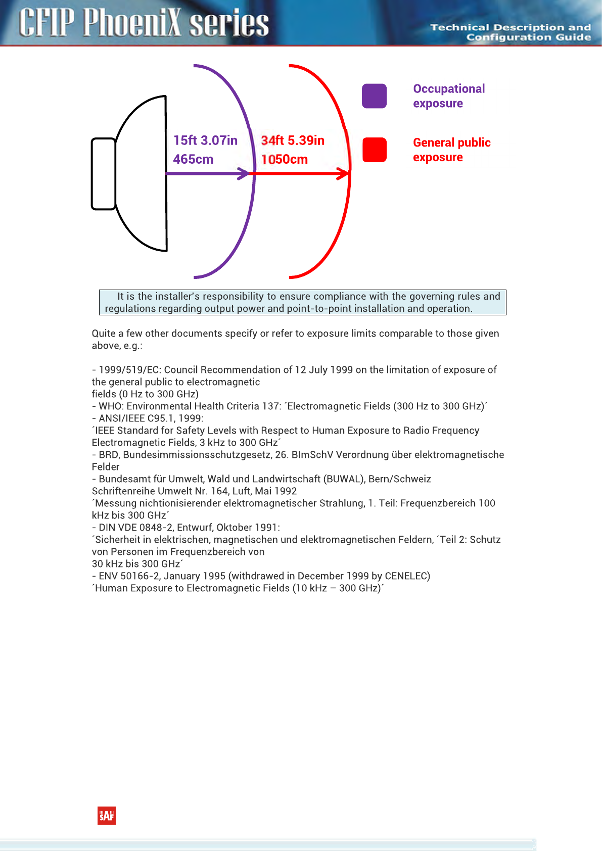
1.7 Microwave Radiation
CFIP PhoeniX 5.8 Technical Description and Configuration Guide • Rev. 1.0 •
© SAF Tehnika JSC 2015
9
(!)
CFIP PhoeniX 5.8 Technical Description and Configuration Guide • Rev. 1.0 •
© SAF Tehnika JSC 2015
10
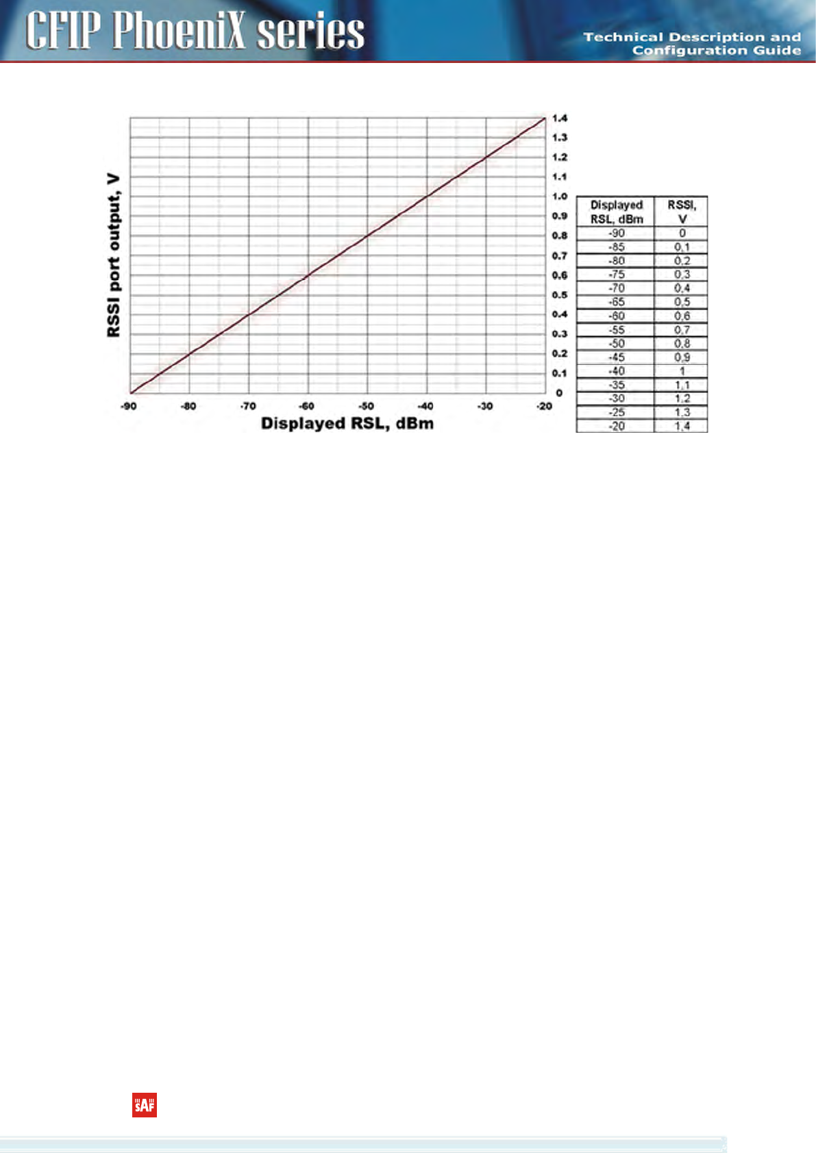
2 RSSI Port
RSSI (Received Signal Strength Indicator) port is used to adjust the alignment of antenna for best
performance (for both rough and fine adjustment); this can be done using digital multimeter which is
connected to the RSSI port. The output of the RSSI port is DC voltage and varies depending on received
signal level.
The following chart and table shows typical relationship of the received signal level (Rx level)
displayed by CFIP vs. RSSI port output voltage (RSSI – Received Signal Strength Indicator). The RSSI port
is located on ODU. The evaluated Rx level has the error +/-2 dB.
Typical RSSI=f(RSL) chart
Figure 2.1 RSSI chart
CFIP PhoeniX 5.8 Technical Description and Configuration Guide • Rev. 1.0 •
© SAF Tehnika JSC 2015
11
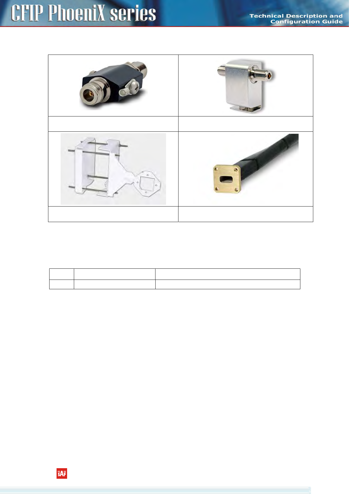
3 Available Accessories
Surge protection
P/N: CLALA001
Surge Protection with gas tube
P/N: CLALA003
CFIP ODU Mounting Bracket
(for 1xODU P/N: CLGRFB05; for 2xODU P/N: CLGRFB06)
Flexible Waveguide UBR
-
PBR
(See the list of available test equipment below)
3.1 Other Available Accessories
CFIP Test Equipment
P/N Name: Description
C06TST02
Test equipment 6 GHz Test equipment 6 GHz

CFIP PhoeniX 5.8 Technical Description and Configuration Guide • Rev. 1.0 •
© SAF Tehnika JSC 2015
12
4 SAF Tehnika JSC Contacts
SAF Tehnika JSC technical support can be reached by:
- Email: techsupport@saftehnika.com
- Telephone: +371 67046840
- Fax: +371 67046809