SAGEMCOM BROANDS FAST1704 Wireless ADSL Router User Manual
SAGEMCOM SAS Wireless ADSL Router Users Manual
Users Manual

Wireless ADSL Router
User Manual
Error! Style not defined.
i
Contents
1 Introduction...................................................................................2
1.1 Application....................................................................2
1.2 Environment Requirements...........................................2
1.3 System Requirements....................................................3
1.4 Safety Cautions .............................................................3
1.5 LED Status Description.................................................4
1.5.1 Front Panel ............................................................4
1.5.2 Rear Panel ............................................................. 5
2 Hardware Installation.................................................................... 5
2.1 Choosing the Best Location for Wireless Operation ..... 6
2.2 Connecting the ADSL Router........................................6
3 Introduction to Web Configuration................................................7
3.1 Logging In to the Modem.............................................. 7
3.2 Summary of Device Information................................... 8
3.3 Advanced Setup.............................................................9
3.3.1 Configuring PPPoE ............................................... 9
3.3.2 Bridge Configuration........................................... 14
3.3.3 Wireless – Basic .................................................. 16
3.3.4 Wireless – Security..............................................17
3.4 Management................................................................ 19
3.4.1 Settings................................................................ 19
3.4.2 System Log..........................................................21
3.4.3 TR-069 Client......................................................23
3.4.4 Access Control ....................................................23
3.4.5 Update Software.................................................. 24
3.4.6 Save/Reboot ........................................................25
4 Q&A............................................................................................26

Error! Style not defined.
2
1 Introduction
The Router is a highly ADSL2+ Integrated Access Device and can
support ADSL link with downstream up to 24 Mbps and upstream up
to 1 Mbps. It is designed to provide a simple and cost-effective
ADSL Internet connection for a private Ethernet or 802.11g/802.11b
wireless network. The Router combines high-speed ADSL Internet
connection, IP routing for the LAN and wireless connectivity in one
package. It is usually preferred to provide high access performance
applications for the individual users, the SOHOs, and the small
enterprises.
Network and Router management is done through the web-based
management interface that can be accessed through the local
Ethernet using any web browser. You may also enable remote
management to enable configuration of the Router via the WAN
interface.
1.1 Application
Home gateway
SOHOs
Small enterprises
TV over IP (IPTV)
Higher data rate broadband sharing
Shared broadband internet access
Audio and video streaming and transfer
PC file and application sharing
Network and online gaming
1.2 Environment Requirements
Operating temperature: 0ºC~45ºC
Storage temperature: -10ºC~55ºC
Error! Style not defined.
3
Operating humidity: 10%~95%, non-condensing
Storage humidity: 5%~95%, non-condensing
Power adapter input: 100V~240V AC, 50/60Hz
Power adapter output: 12V DC, 0.8A
1.3 System Requirements
Recommended system requirements are as follows:
Pentium 233 MHZ or above
Memory: 64 Mbps or above
10M Base-T Ethernet or above
Windows 9x, Windows 2000, Windows XP, Windows ME,
Windows NT
Ethernet network interface card
1.4 Safety Cautions
Follow the announcements below to protect the device from risks
and damage caused by fire and electric power.
Use volume labels to mark the type of power.
Use the power adapter that is packed within the device package.
Pay attention to the power load of the outlet or prolonged lines.
An overburden power outlet or damaged lines and plugs may
cause electric shock or fire accident. Check the power cords
regularly. If you find any damage, replace it at once.
Proper space left for heat radiation is necessary to avoid any
damage caused by overheating to the device. The holes are
designed for heat radiation to ensure that the device works
normally. Do not cover these heat radiant holes.
Do not put this device close to a place where a heat source exits
or high temperature occurs. Avoid the device from direct
sunshine.
Do not put this device close to a place where is over damp or
watery. Do not spill any fluid on this device.
Do not connect this device to any PC or electronic product,
unless our customer engineer or your broadband provider
Error! Style not defined.
4
instructs you to do this, because any wrong connection may
cause any power or fire risk.
Do not place this device on an unstable surface or support.
1.5 LED Status Description
1.5.1 Front Panel
Indicator Status Description
Off The power is off.
Green The power is on and the device operates
normally.
The power is self-testing.
The device enters the console mode of
the boot loader.
Red
The self-testing of the power fails if the
LED is always red.
Power
Blink Red Upgrading software.
Off No signal is detected.
Slow Blink Green The DSL line is transferring.
Fast Blink Green The DSL line is training.
ADSL
Green The DSL line connection is established.
Off No PPPoA or PPPoE connection
Green The PPPoA or PPPoE connection is
established. The users can access the
Internet.
Internet
Red
Device attempts to become IP
connected but fails (no DHCP response,
no PPPoE response, PPPoE
authentication failed, no IP address
from IPCP, etc.)
Off No Ethernet signal is detected.
Blink Green The user data is passing through
Ethernet port.
LAN1/2/3/4
Green Ethernet interface is ready to work
WLAN Off No radio signal is detected.
Error! Style not defined.
5
Indicator Status Description
Blink Green The user data is passing through
WLAN port.
Green WLAN interface is ready to work.
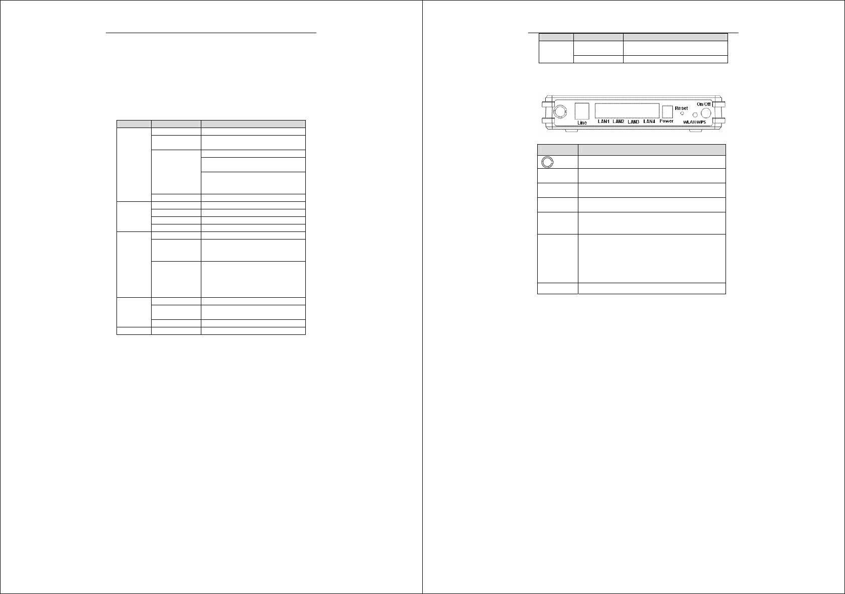
1.5.2 Rear Panel
Interface Description
Wireless antenna.
Line RJ-11 port, using the telephone line to connect the
modem with the ADSL cable or splitter.
LAN 1~4 RJ-45 port, connect the modem to a PC or other
network device.
Power Power supplied port, plug in for power adapter that the
power input is 12V DC, 1 A.
Reset To restore the factory default, keep the device powered
on and push a needle into the hole. Press down the
button about 3 seconds and then release.
WLAN/WPS
Press the button silently less than 1s to enable
WLAN function.
Press the button for more than 5s to enable to
enable WPS function.
If you press the button between 1s and 5s, no
function takes effective.
On/Off Power switch.
2 Hardware Installation
Error! Style not defined.
6
2.1 Choosing the Best Location for
Wireless Operation
Keep the numbers of walls and ceilings to the minimum:
The signal emitted from wireless LAN devices can penetrate
through ceilings and walls. However, each wall or ceiling can
reduce the range of wireless LAN devices from 1 ~ 30 miters.
Position your wireless devices so that the number of walls or
ceilings obstructing the signal path is minimized.
Consider the direct line between access points and workstations:
A wall that is 0.5 meters thick, at a 45-degree angle appears to
be almost 1 meter thick. At a 2-degree angle, it appears over 14
meters thick. Be careful to position access points and client
adapters so the signal can travel straight through (90º angle) a
wall or ceiling for better reception.
Building materials make difference:
Buildings constructed using metal framing or doors can reduce
effective range of the device. If possible, position wireless
devices so that their signals can pass through drywall or open
doorways. Avoid positioning them in the way that their signal
must pass through metallic materials. Poured concrete walls are
reinforced with steel while cinderblock walls generally have
little or no structural steel.
Position the antenna for best reception:
Play around with the antenna position to see if signal strength
improves. Some adapters or access points allow you to judge
the strength of the signal.
Keep your product away (at least 1~2 meters) from electrical
devices:
Keep wireless devices away from electrical devices that
generate RF noise such as microwave ovens, monitors, electric
motors, etc.
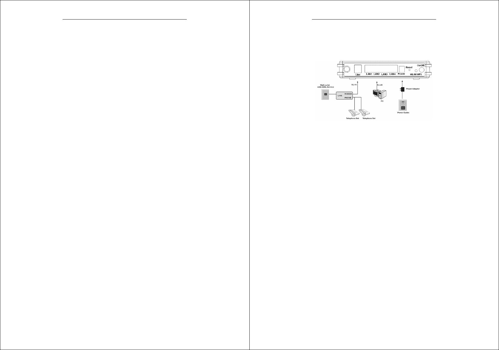
2.2 Connecting the ADSL Router
Error! Style not defined.
7
See the following figure. Connect the Line port of the DSL
Router with a telephone cable.
Connect the LAN port of the DSL Router to the network card of
the PC via an Ethernet cable.
Plug one end of the power adapter to the wall outlet and connect
the other end to the PWR port of the DSL Router.
The following figure displays the connection of the DSL Router, PC,
and telephones.
3 Introduction to Web Configuration
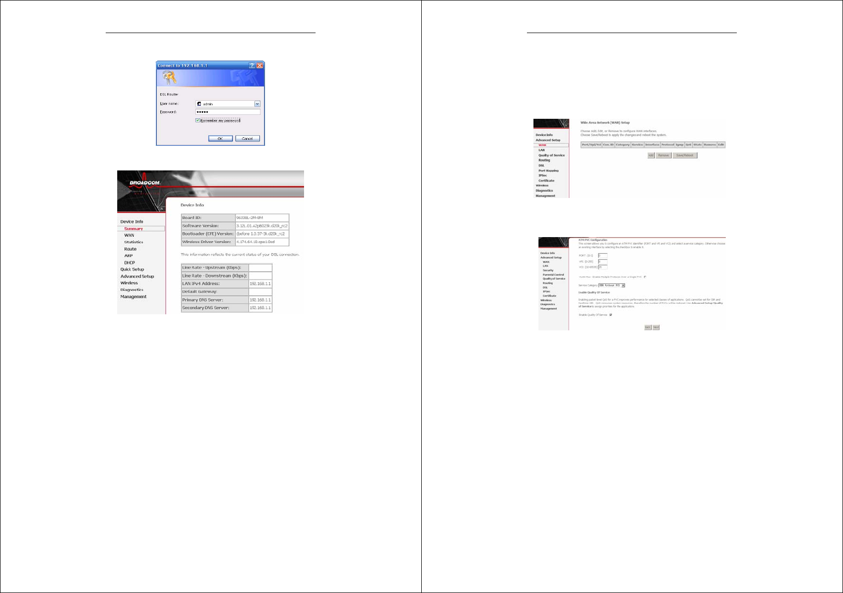
3.1 Logging In to the Modem
Step 1 Open a Web browser on your computer.
Step 2 Enter http://192.168.1.1 (DSL router default IP address) in
the address bar. The login page appears.
Step 3 Enter a user name and the password. The default username
and password of the super user are admin and admin. The
username and password of the common user are user and
user. You need not enter the username and password again
if you select the option Remember my password. It is
Error! Style not defined.
8
recommended to change these default values after logging in
to the DSL router for the first time.
Step 4 Click OK to log in or click Cancel to exit the login page.
3.2 Summary of Device Information
Error! Style not defined.
9
Default Gateway: In the bridging mode there is no gateway. In
other modes, it is the address of the uplink equipment, for
example, PPPoE/PPPoA.
DNS Server: In the PPPoE / PPPoA mode, it is obtained from
the uplink equipment. In the bridging mode, there is no DNS
Server address and you can manually enter the information.
3.3 Advanced Setup
Choose Advanced Setup > WAN, and the following page appears.
3.3.1 Configuring PPPoE
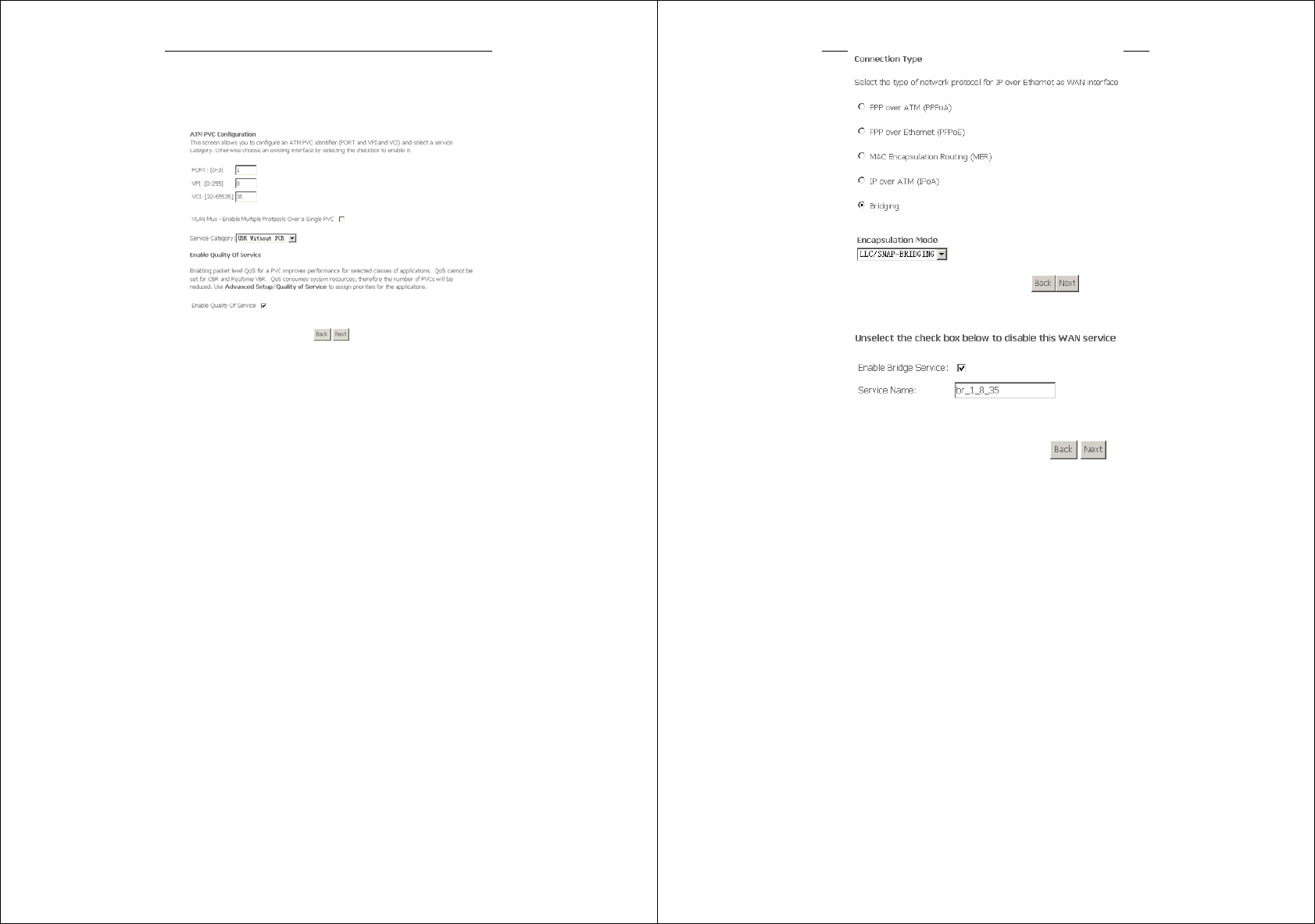
Step 1 Click Add and the following page appears. In this page, you
can modify VPI/VCI, service categories, and QoS.
Error! Style not defined.
10
VPI: Virtual path between two points in an ATM network. Its
valid value range is from 0 to 255.
VCI: Virtual channel between two points in an ATM network.
Its valid value range is from 32 to 65535 (1 to 31 are reserved
for known protocols).
Service Category: UBR Without PCR/UBR With
PCR/CBR/Non Realtime VBR/Realtime VBR.
Enable Quality Of Service: Enable or disable QoS.
After proper modifications, click Next and the following page
appears.
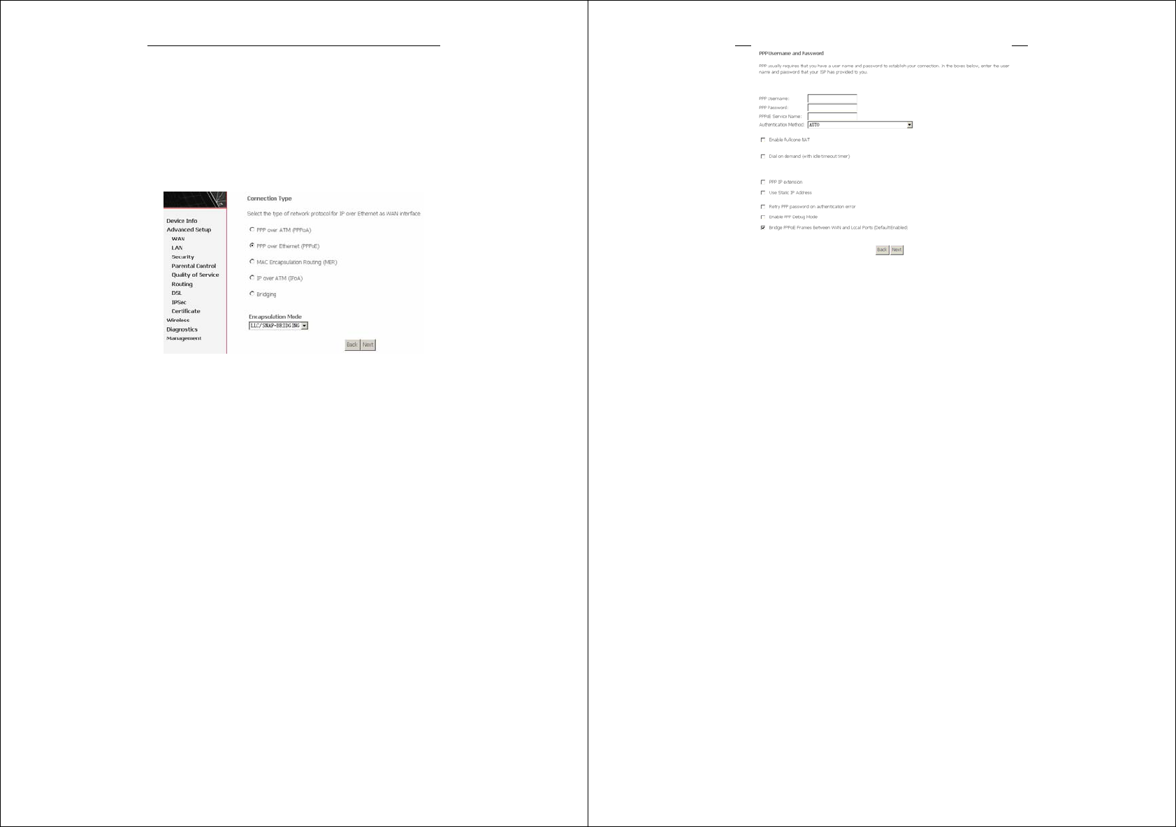
Step 2 In this page, you can modify the Internet connection type
and encapsulation type.
Change the connection type of PVC 0/35 to PPP over Ethernet
(PPPoE) and set the Encapsulation Mode to LLC/SNAP-BRIDGING
(according to the uplink equipment). Click Next and the following
page appears.
Step 3 In this page, you can modify the PPP user name, PPP
password, authentication method.
Error! Style not defined.
11
PPP Username: The correct user name that your ISP provides to
you.
PPP Password: The correct password that your ISP provides to you.
PPPoE Service Name: If your ISP provides it to you, please enter it.
If not, do not enter any information.
Authentication Method: The value can be AUTO, PAP, CHAP, or
MSCHAP. Usually, you can select AUTO.
Dial on demand (with idle timeout timer): If this function is
enabled, you need to enter the idle timeout time. Within the preset
minutes, if the modem does not detect the flow of the user
continuously, the modem automatically stops the PPPOE connection.
Once it detects the flow (like access to a webpage), the modem
restarts the PPPOE dialup.
If this function is disabled, the modem performs PPPOE dial-up all
the time. The PPPOE connnection does not stop, unless the modem
is powered off and DSLAM or uplink equipment is abnormal.
Error! Style not defined.
12
PPP IP extension: If this function is enabled, the WAN IP address
obtained by the modem through built-in dial-up can be directly
assigned to the PC being attached to the modem (at this time, the
modem connects to only one PC). From the aspect of the PC user,
the PC dials up to obtain an IP addres. But actually, the dial-up is
done by the modem.
If this function is disabled, the modem itself obtains the WAN IP
address.
Use Static IP Address: If this function is disabled, the modem
obtains an IP address assigned by an uplink equipment such as BAS,
through PPPoE dial-up.If this function is enabled, the modem uses
this IP address as the WAN IP address.
After entering the PPP user name and password, click Next and the
following page appears.
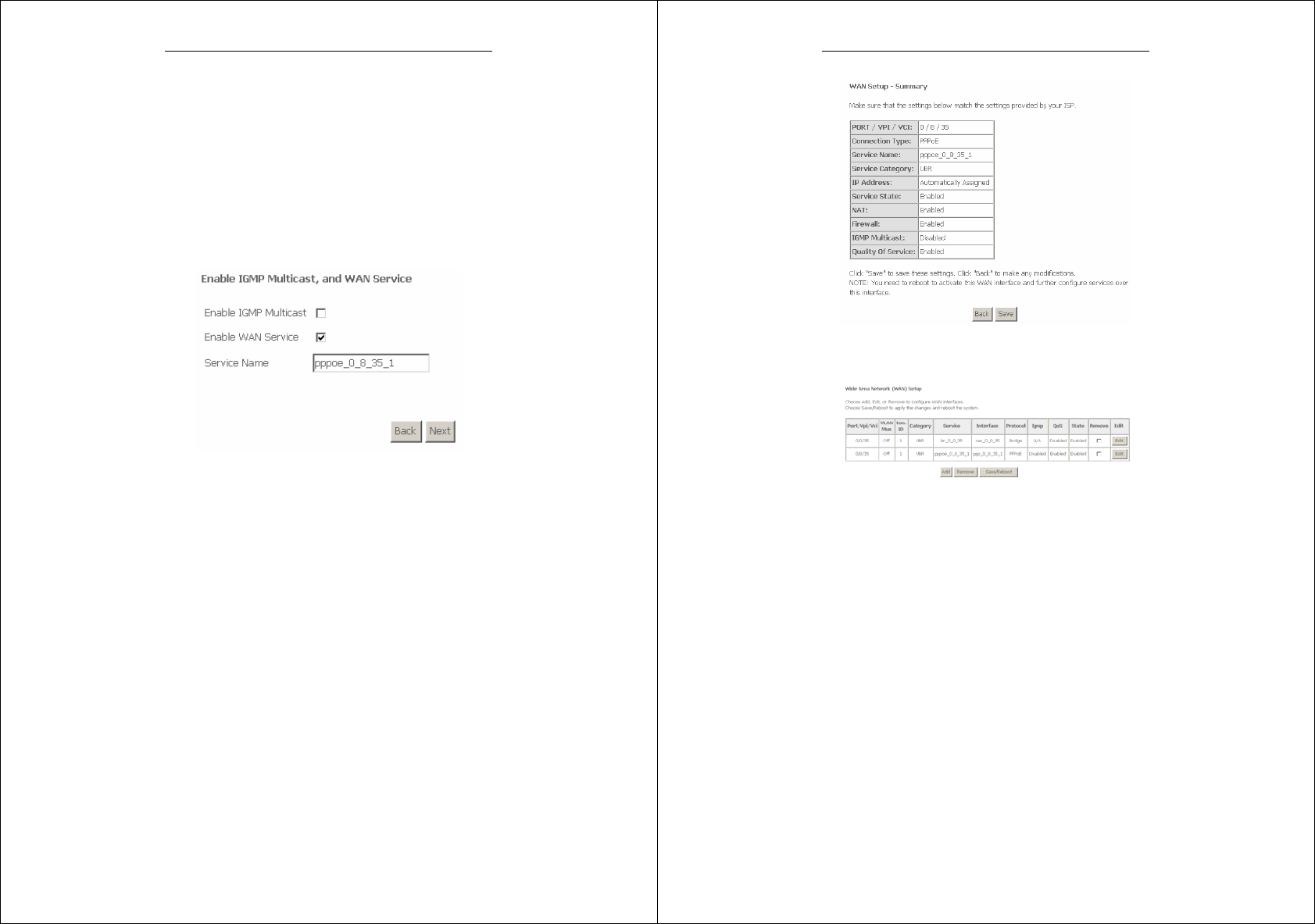
In this page, you can modify the service name, and enable or disable
the IGMP multicast and WAN service.
Enable IGMP Multicast: IGMP proxy. For example, if you wish
that the PPPoE mode supports IPTV, enable this function.
Enable WAN Service: Enable it, unless you do not want to active
the PVC.
Click Next and the following page appears.
Error! Style not defined.
13
This page shows all the configuration. You can view the default
values of NAT enable and Firewall enable.
To save the settings, click Save. To make any modifications, click
Back. After you click Save, the following page appears.
Note: You need to reboot the modem to activate this WAN interface
and further configure services in this interface.
Error! Style not defined.
14
3.3.2 Bridge Configuration
This section describes the procedure for adding PVC 0/35 (IPoA
mode).
Click Add, and the following page appears. In this page, you can
modify VPI/VCIs, service categories, and QoS.
In this example, PVC 0/35 is to be modified and the default values of
service category remain. In actual applications, you can modify them
as required.
After proper modifications, click Next and the following page
appears.
In this page, you can modify the Internet connection type and
encapsulation type.
Error! Style not defined.
15
Click Next and the following page appears.
In this page, you can modify the service name.
Enable Bridge Service: Enable it, unless you do not want to active
the PVC.
Click Next and the following page appears.
This page shows all the configuration.
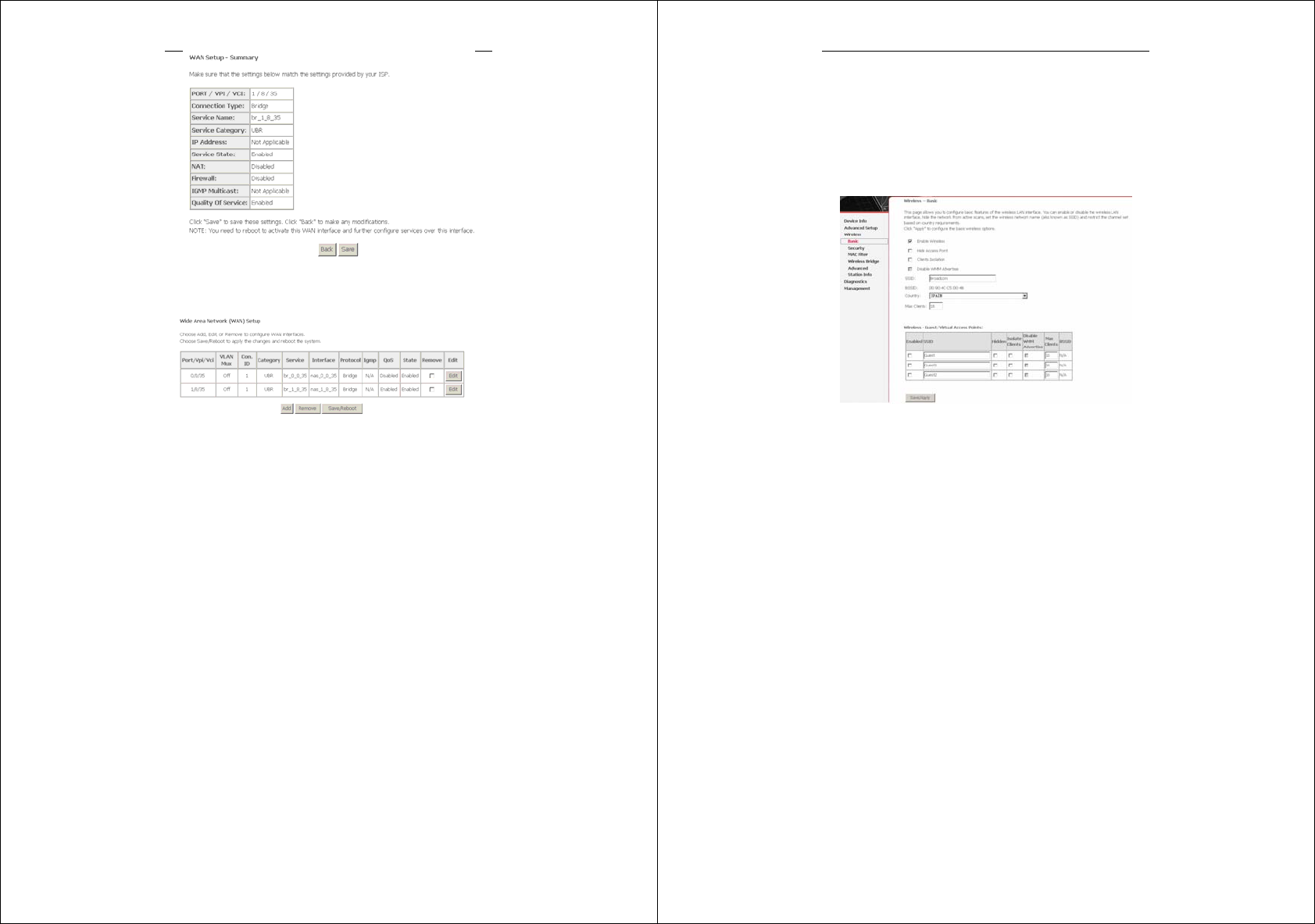
Error! Style not defined.
16
To save the settings, click Save. To make any modifications, click
Back. After you click Save, the following page appears.
Note: You need to reboot the modem to activate this WAN interface
and further configure services in this interface.
3.3.3 Wireless – Basic
Enable Wireless: If you want to make wireless be available,
you have to check this box first. Otherwise, the Hide Access
Point SSID, Country, Enable Wireless Guest Network, and
Guest SSID box will not be displayed.
Hide Access Point: Check this box if you want to hide any
Error! Style not defined.
17
access point for your router, so a station cannot obtain the SSID
through passive scanning.
SSID: The SSID (Service Set Identification) is the unique name
shared among all devices in a wireless network. The SSID must
be identical for all devices in the wireless network.
Country: The channel will adjust according to nations to adapt
to each nation's frequency provision.
Guest SSID: The SSID (Service Set Identification) is the
unique name shared among all devices in a guest wireless
network. The SSID must be identical for all devices in the guest
wireless network.
3.3.4 Wireless – Security
Select SSID: Select the wireless LAN of SSID to configure
security features.
No Encryption: Please refer to below for details of
configuration
Network Authentication: Select the authentication mode for the
selected wireless LAN of SSID to be open.
WEP Encryption: Disable WEP Encryption.
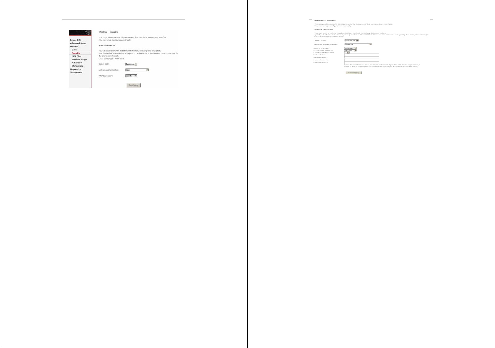
Error! Style not defined.
18
The data is not encrypted when it is transferred from the device to
the client station. This is the default option.
64-bit WEP
Network Authentication: Select the authentication mode for the
selected wireless LAN of SSID to be open or shared.
WEP Encryption: Enable WEP Encryption.
Encryption Strength: click the desired Data Security level to be
64-bit.
Current Network Key: Select one of network key that you set
on the Key boxes as default one.
Network Key 1 to 4: Enter 5 ASCII characters or 10
hexadecimal digits for 64-bit encryption keys to fill out WEP
keys box. The system allows you to type in 4 kinds of the WEP
key.
Click Save/Apply to save the wireless security options and make the
modification effect.
Error! Style not defined.
19
128-bit WEP
Encryption Strength: Click the desired Data Security level to be
128-bit.
Current Network Key: Select one of network key that you set
on the Key boxes as default one.
Network Key 1 to 4: Enter 13 ASCII characters or 26
hexadecimal digits for 128-bit encryption keys to fill out WEP
keys box. The system allows you to type in 4 kinds of the WEP
key.
The authentication modes are as follows: 802.1X, WPA,
WPA-PSK,WPA2, WPA2 –PSK, Mixed WPA2/WPA, Mixed
WPA2/WPA –PSK.
After proper configuration, click Save/Apply to save the wireless
security options and make the modification effect.
3.4 Management
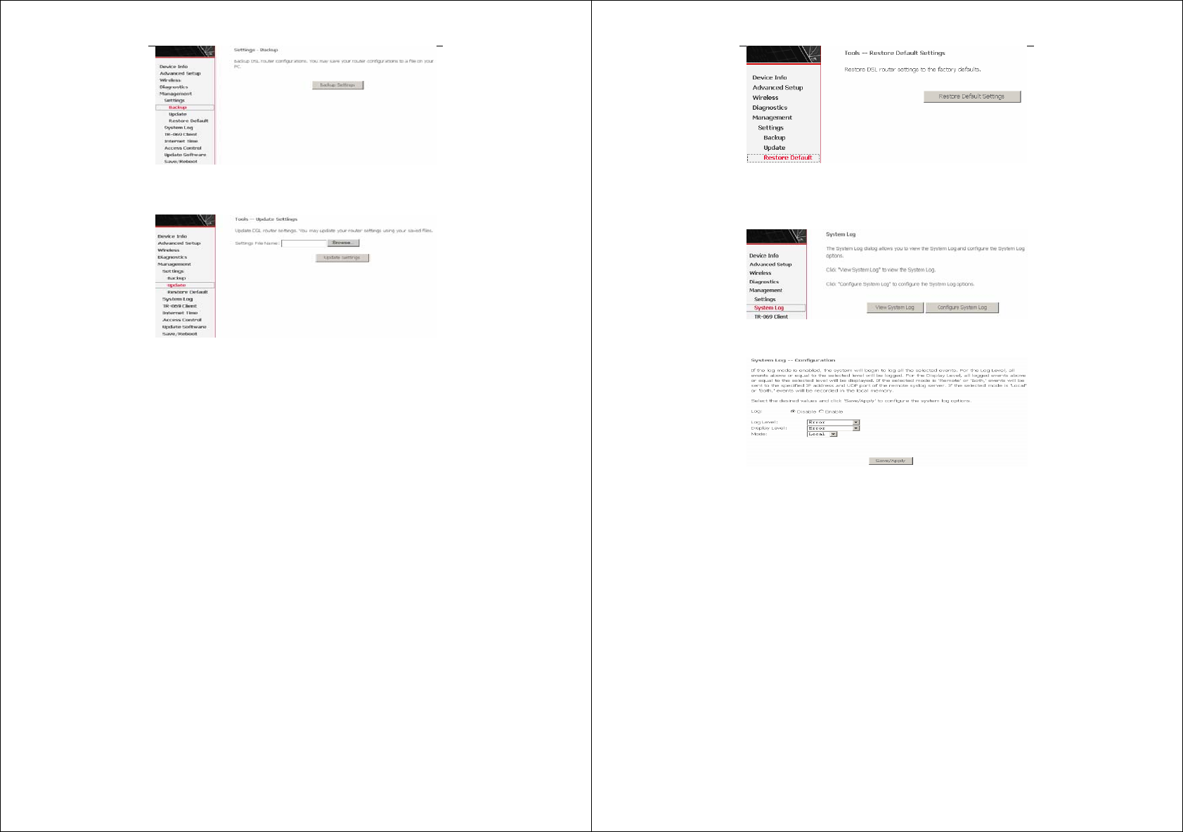
3.4.1 Settings
3.4.1.1 Settings Backup
Click Backup Settings to back up the DSL router configuration.
Error! Style not defined.
20
3.4.1.2 Settings Update
Click Browser and select the correct update configure settings file.
Then, click Update Settings to update the modem settings.
3.4.1.3 Settings Restore Default
Click Restore Default Settings to restore DSL router settings to the
factory defaults.
Error! Style not defined.
21
3.4.2 System Log
Click System Log to show the following interface. The system log
dialog allows you to view the system log and configure the system
log options.
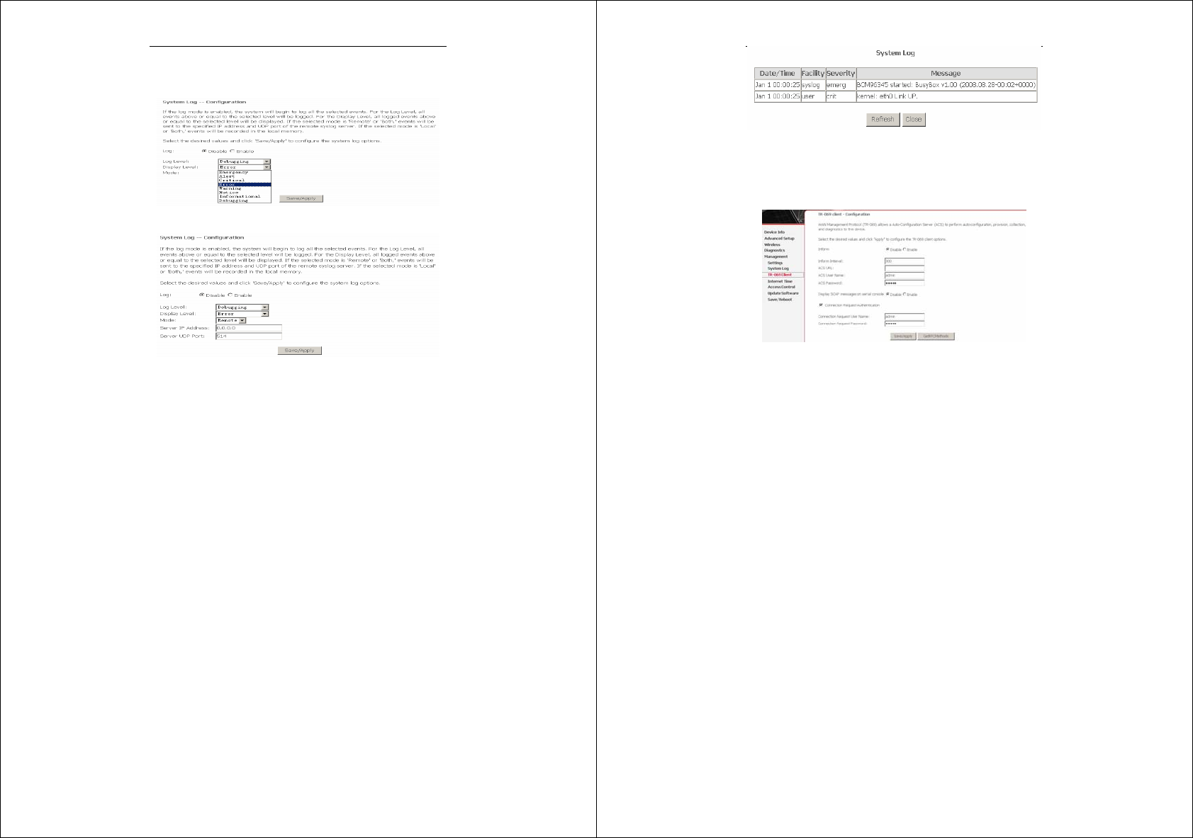
Click Configure System Log to show the following interface. You
can enable or disable the system log and then select the log level,
display level and mode, and click Apply to end your configurations.
Error! Style not defined.
22
Both the log level and display level have eight choices. The default
log level is Debugging and the default display level is Error.
The mode options are Local, Remote, and Both. The default is
Local.
If you select Remote or Both, all events are transmitted to the
specified UDP port of the specified log server.
After operations under Configure System Log, click View System
Log to query the system logs. In this example, the View System Log
is the default.
Note: The log and display of the system events are above the set level.
If you intend to record all information, you need to set the
levels as Debugging.
Error! Style not defined.
23
Click Refresh to refresh the system event logs or click Close to exit
from this interface.
3.4.3 TR-069 Client
Select the desired values and click Save/Apply to configure the
TR-069 client options.
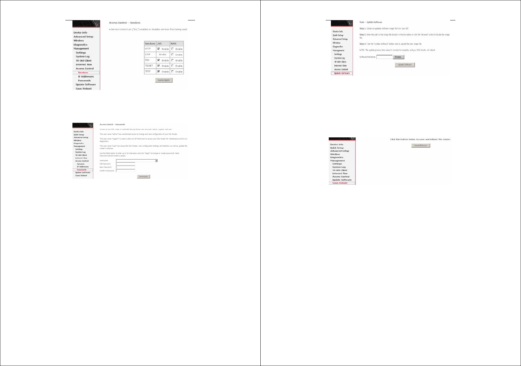
3.4.4 Access Control
3.4.4.1 Access Control – Services
Click Access Control > Services to show the following interface. In
the interface, you can enable or disable HTTP, ICMP, SSH, TELNET
and TFTP services. And the LAN side and WAN side can have
different configurations.
Error! Style not defined.
24
Note: If the connection is PPPoE PVC, you can view the information
of WAN side.
3.4.4.2 Access Control – Passwords
Click Access Control > Passwords to show the following interface.
In the interface, you can modify the accounts passwords.
3.4.5 Update Software
Click Update Firmware to show the following interface. In this
interface, you can update the modem firmware. Click Browse to find
the right version file and click Update Firmware to update.
Error! Style not defined.
25
Note: Do not turn off your modem during firmware updates. When
the update is finished, the modem reboots automatically. Do
not turn off your modem either before the reboot is over. You
must guarantee the update software is right and accurate. It is
strictly forbidden to use other software for updates.
After update software, it is suggested to restore the modem to the
factory defaults and configure it again.
3.4.6 Save/Reboot
Click Save/Reboot to show the following interface. Click
Save/Reboot to save and reboot the router.

4 Q&A
(1) Q: Why all LED indicators are off?
A:
Check the connection between the power adaptor and the
power socket.
Check the power switch is on or not.
(2) Q: Why LAN LED is not lighting?
A:
Check the connection between the ADSL modem and
your computer, hub, or switch.
Check the running status of your PC, hub, or switch, and
ensure that they are working normally.
(3) Q: Why ADSL LED is not lighting?
A: Check the connection between the ADSL “Line” port and the
wall jack.
(4) Q: Why cannot visit Internet with ADSL LED is on?
A: Ensure that the following information is correctly entered.
VPI/VCI
Username/password.
(5) Q: Why cannot open the Modem Web configuration page?
A: Follow below steps to check the communication between the
computer and modem.
Choose Start > Run from the desktop, and ping
192.168.1.1 (the IP address of the modem).
If the modem cannot be reached, please check following
configuration:
– Type of the network cable
– Connection between the modem and computer
– TCP/IP configuration of you computer
(6) Q: How to load the default setting after incorrect configuration?
A:
Error! Style not defined.
27
To restore the factory default, keep the device powered on
and push a needle into the hole. Press down the button
about one second and then release.
The default IP address and subnet mask of the modem are
192.168.1.1 and 255.255.255.0 respectively.
The Username and password are admin and admin
respectively.
FCC Caution:
Any Changes or modifications not expressly approved by the party
responsible for compliance could void the user's authority to
operate the equipment.
This device complies with part 15 of the FCC Rules. Operation is
subject to the following two conditions: (1) This device may not
cause harmful interference, and (2) this device must accept any
interference received, including interference that may cause
undesired operation.
FCC Radiation Exposure Statement:
This equipment complies with FCC radiation exposure limits
set forth for a uncontrolled environment .This equipment
should be installed and operated with minimum distance 20
cm between the radiator& your body.
This transmitter must not be co-located or operating in conjunction
with any other antenna or transmitter.
Note: This equipment has been tested and found to comply with the
limits for a Class B digital device, pursuant to part 15 of the FCC

Error! Style not defined.
28
Rules. These limits are designed to provide reasonable protection
against harmful interference in a residential installation. This
equipment generates, uses and can radiate radio frequency energy
and, if not installed and used in accordance with the instructions,
may cause harmful interference to radio communications. However,
there is no guarantee that interference will not occur in a particular
installation. If this equipment does cause harmful interference to
radio or television reception, which can be determined by turning the
equipment off and on, the user is encouraged to try to correct the
interference by one or more of the following measures:
—Reorient or relocate the receiving antenna.
—Increase the separation between the equipment and receiver.
—Connect the equipment into an outlet on a circuit different from
that to which the receiver is connected.
—Consult the dealer or an experienced radio/TV technician for help.