SAGEMCOM BROANDS HILO3G GSM/GPRS/EDGE AND WCDMA/HSDPA MODULE User Manual
SAGEMCOM SAS GSM/GPRS/EDGE AND WCDMA/HSDPA MODULE Users Manual
UserManual.wiki
>
SAGEMCOM BROANDS
>
HILO3G User Manual
Users Manual
Navigation menu
Upload a User Manual
Namespaces
Wiki Guide
HTML
PDF
Info
Views
User Manual
Discussion / Help
Navigation
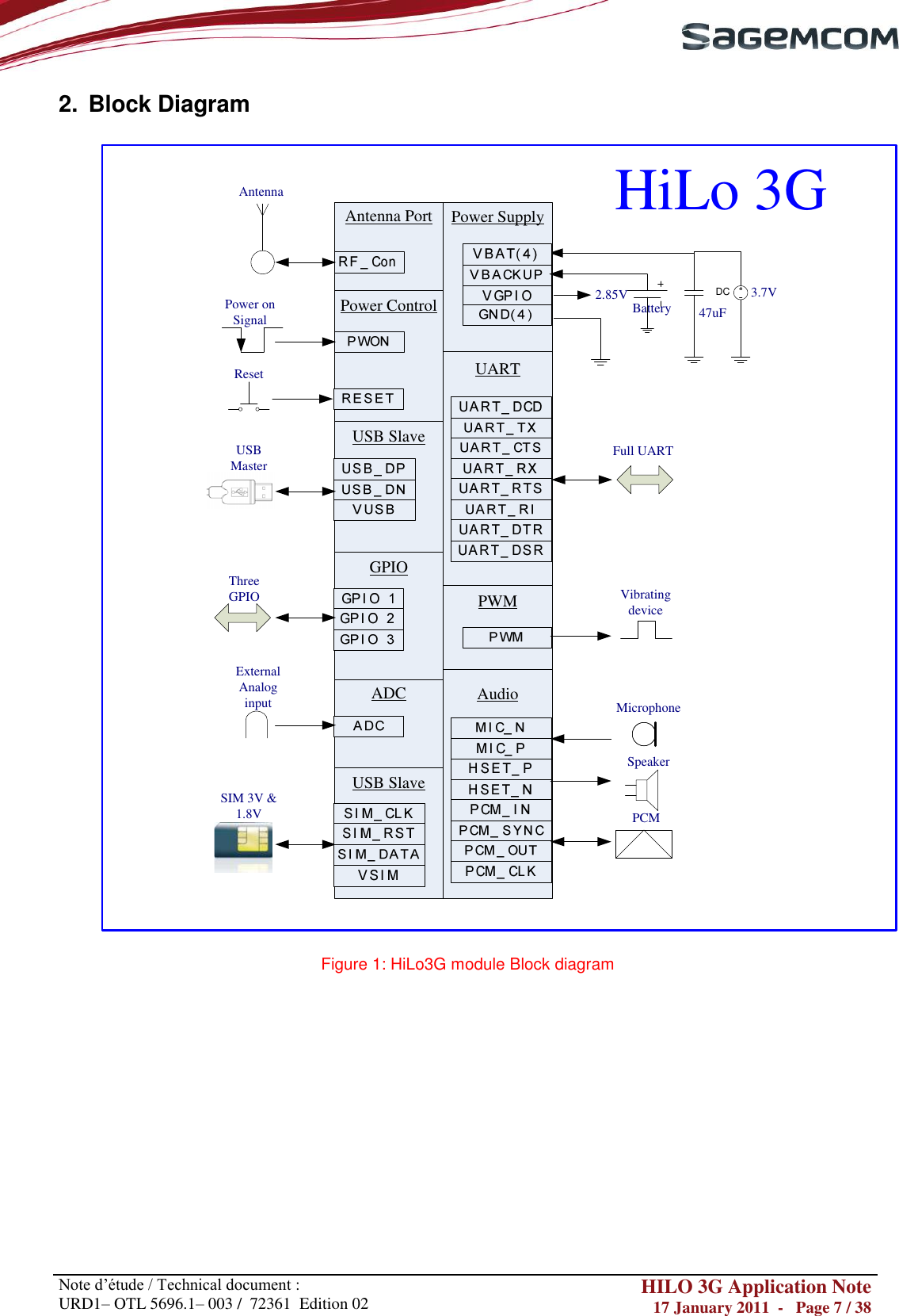
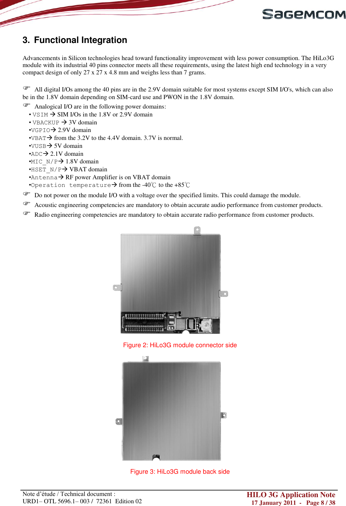
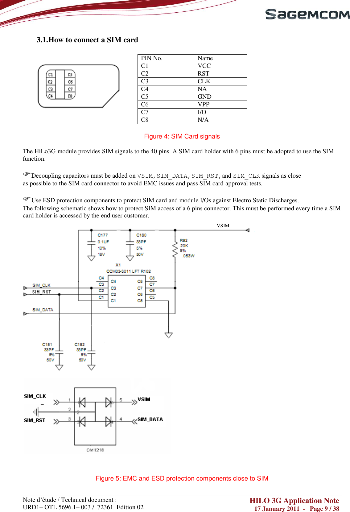
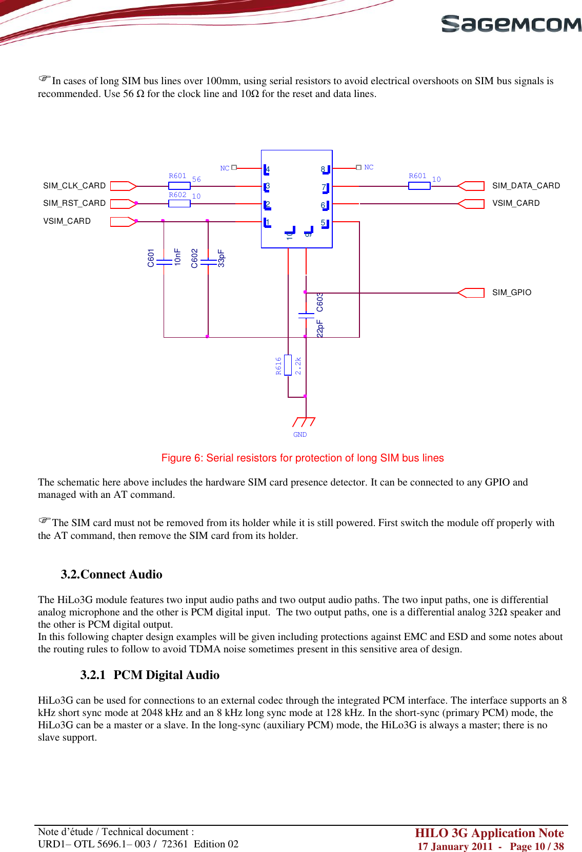
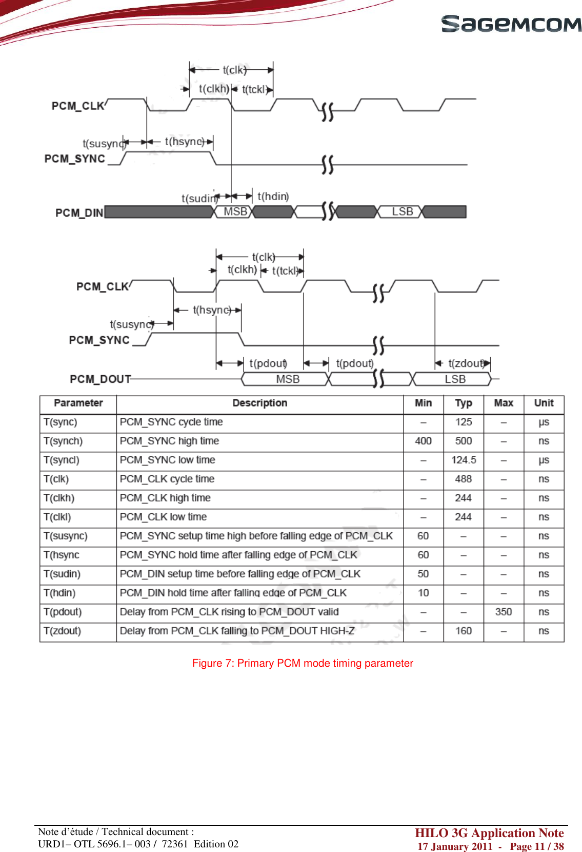
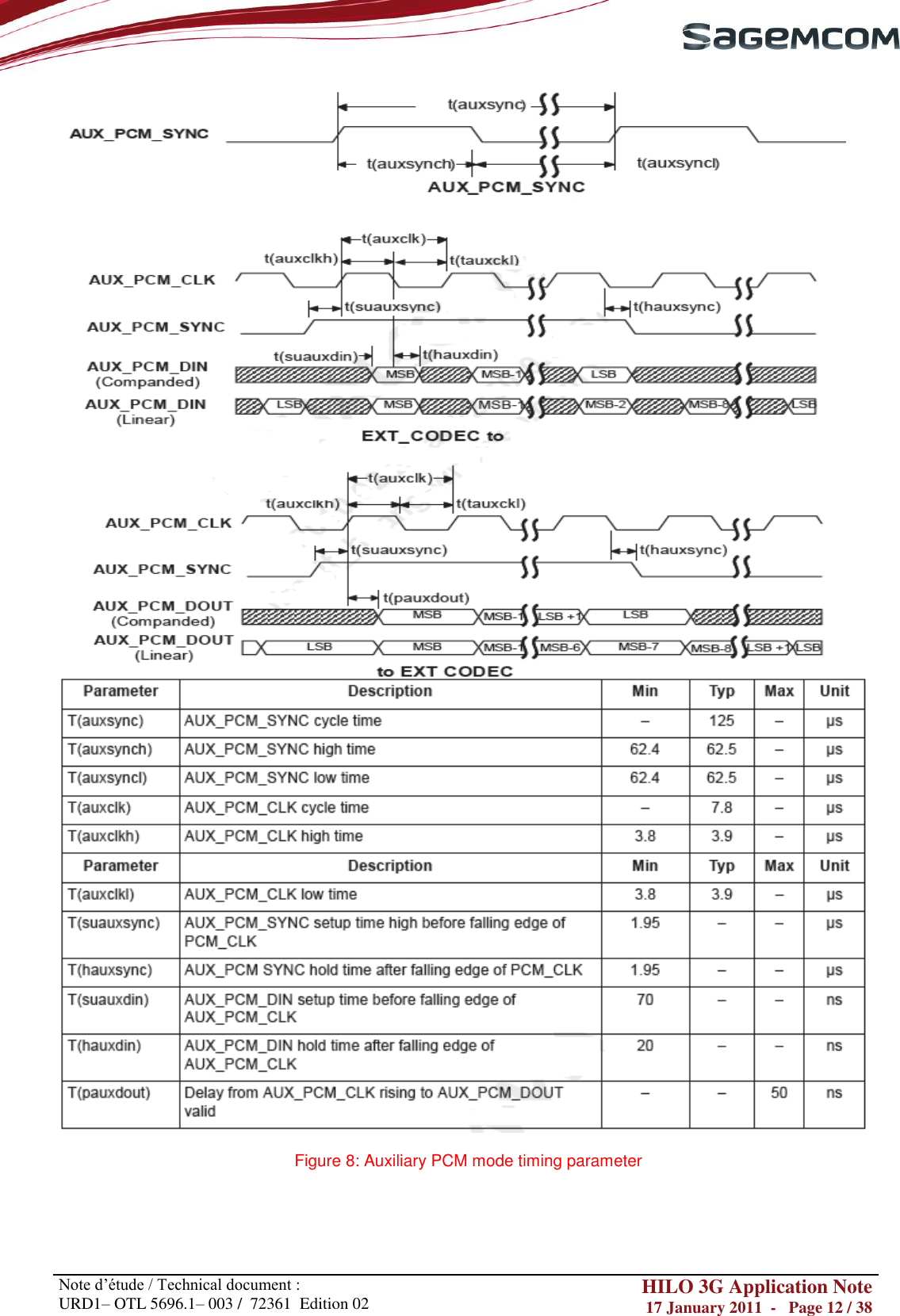
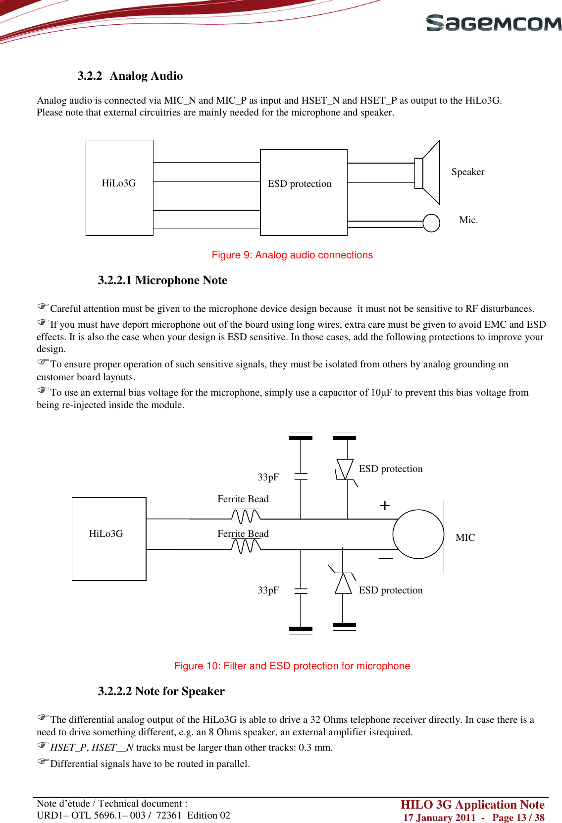
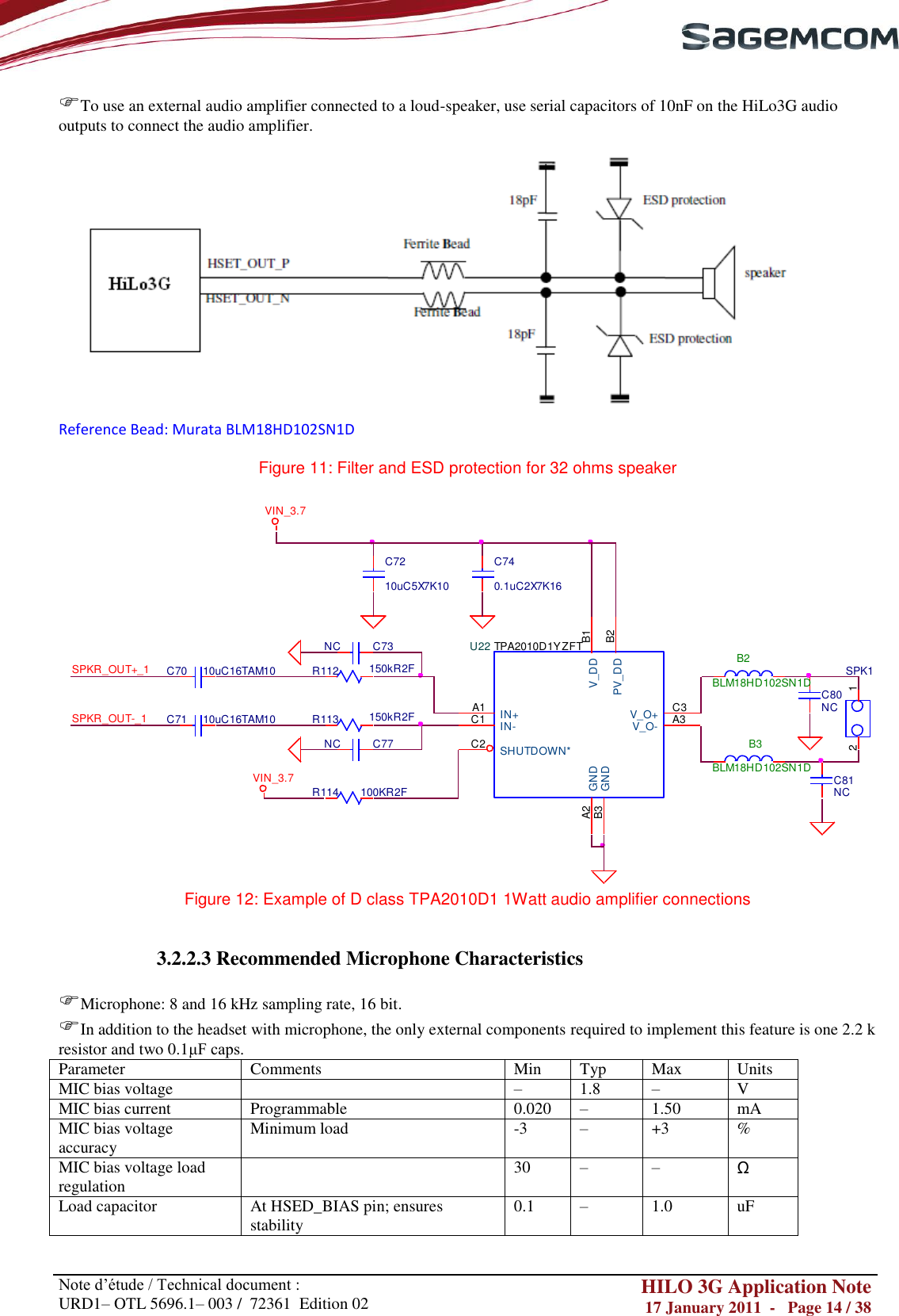
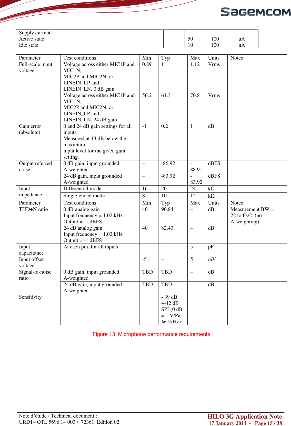
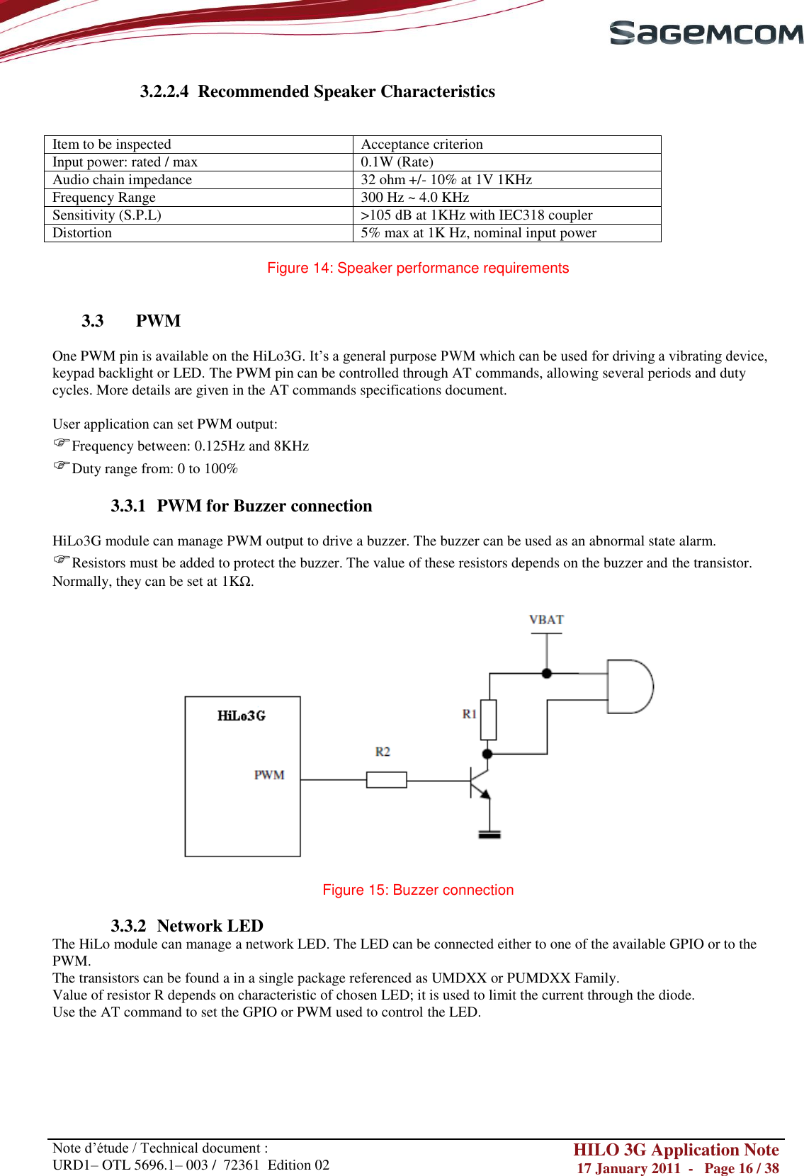
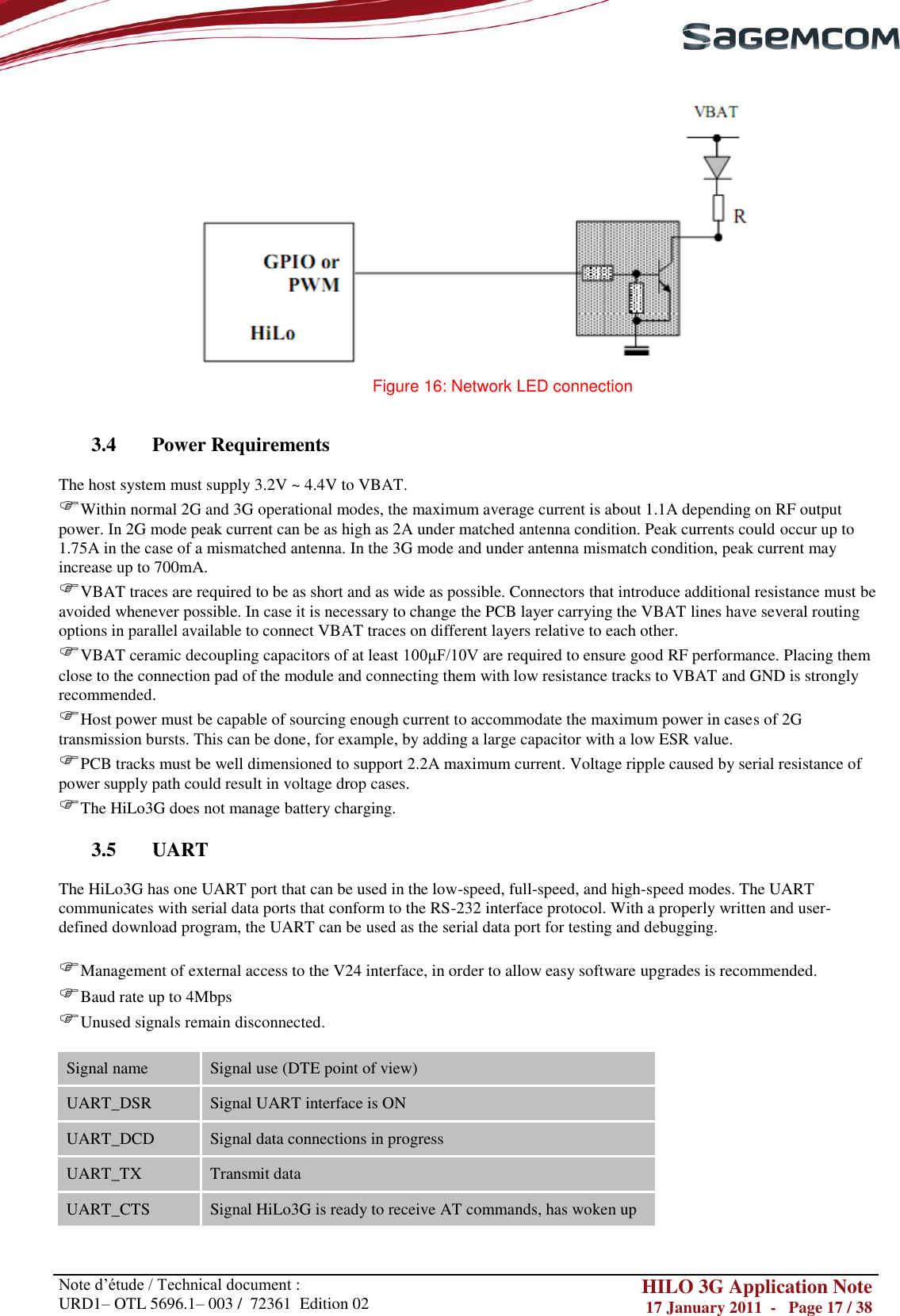
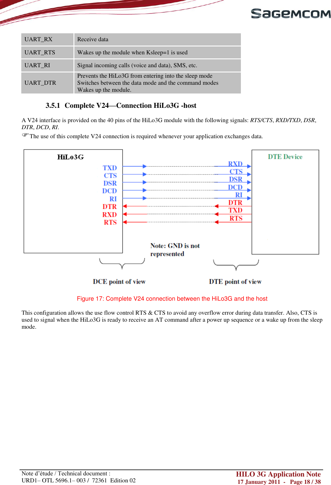
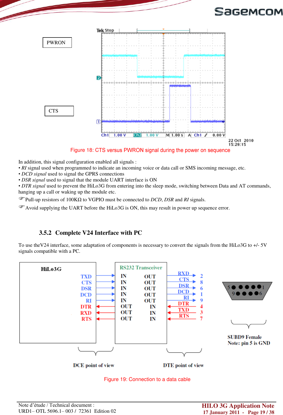
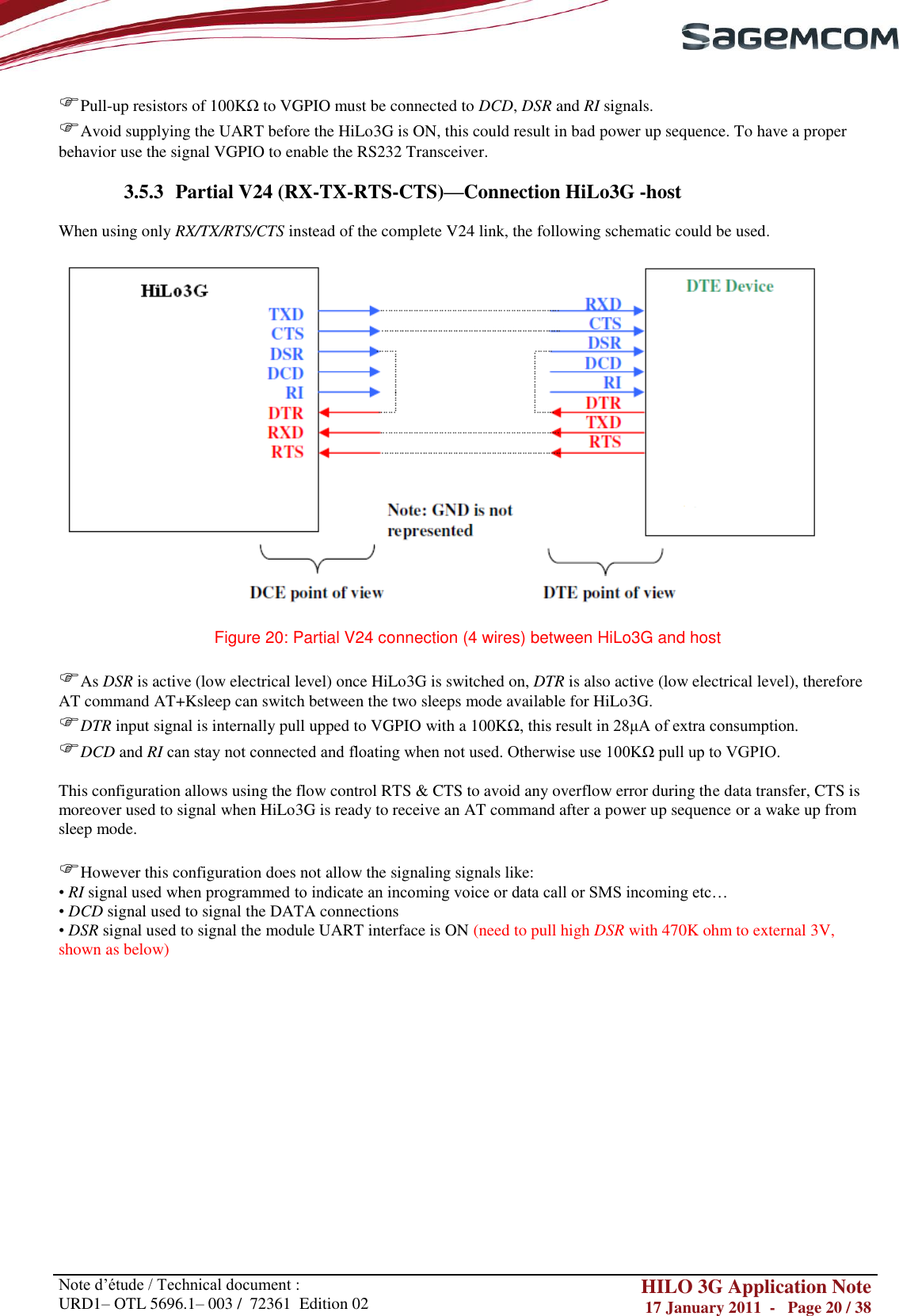
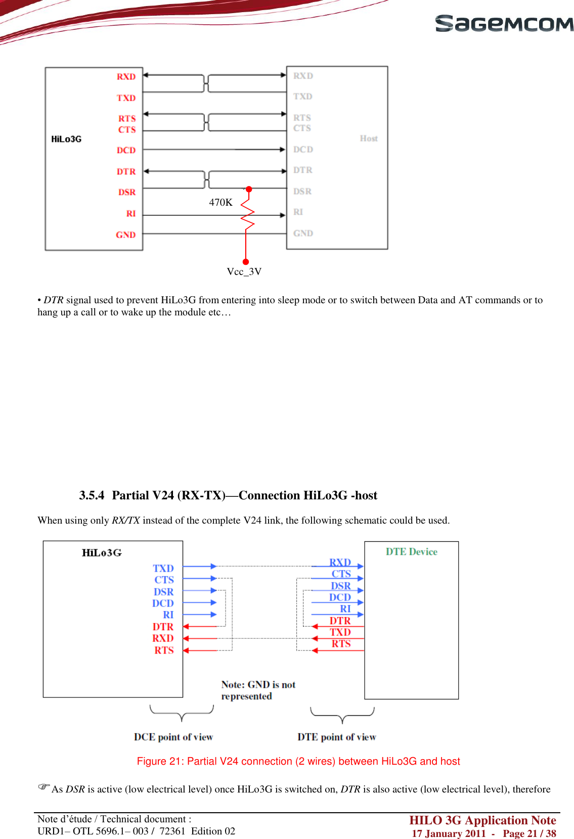
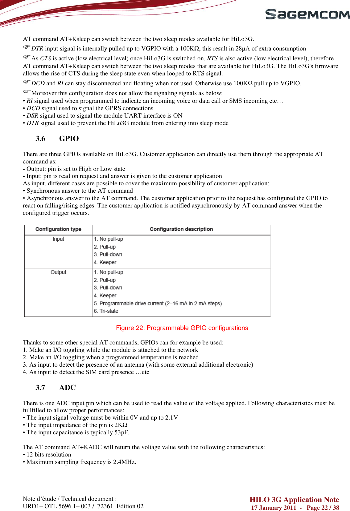
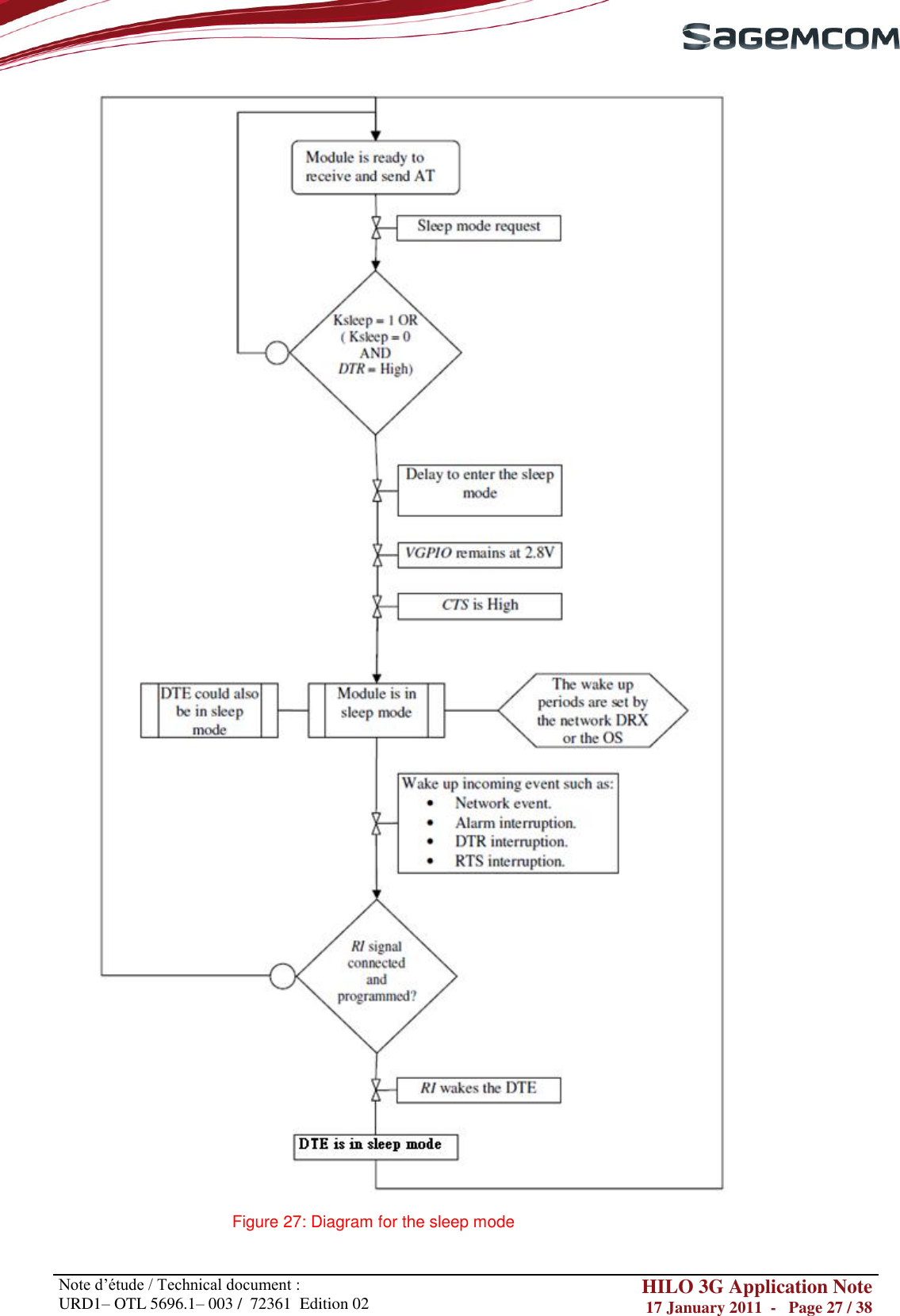
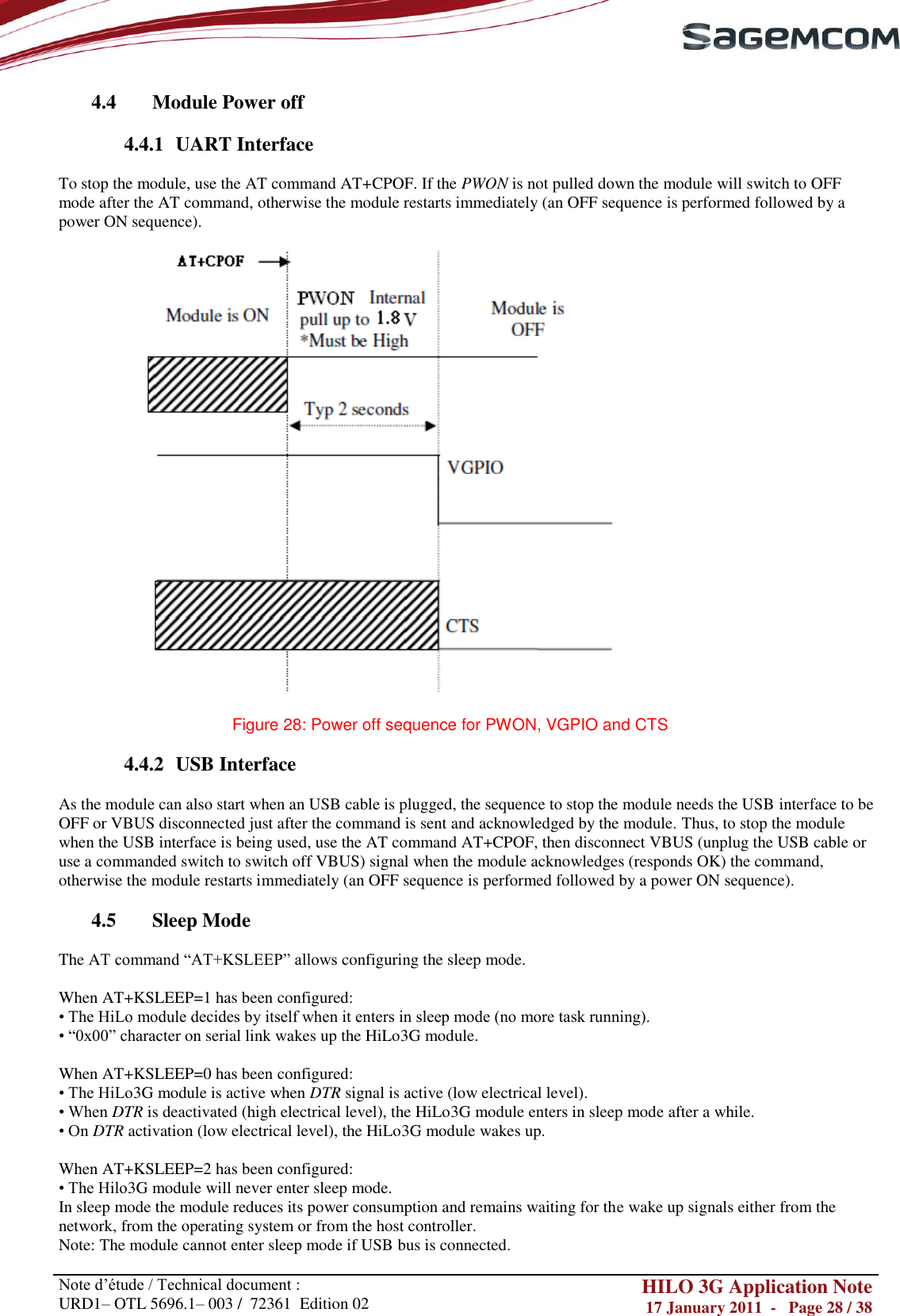
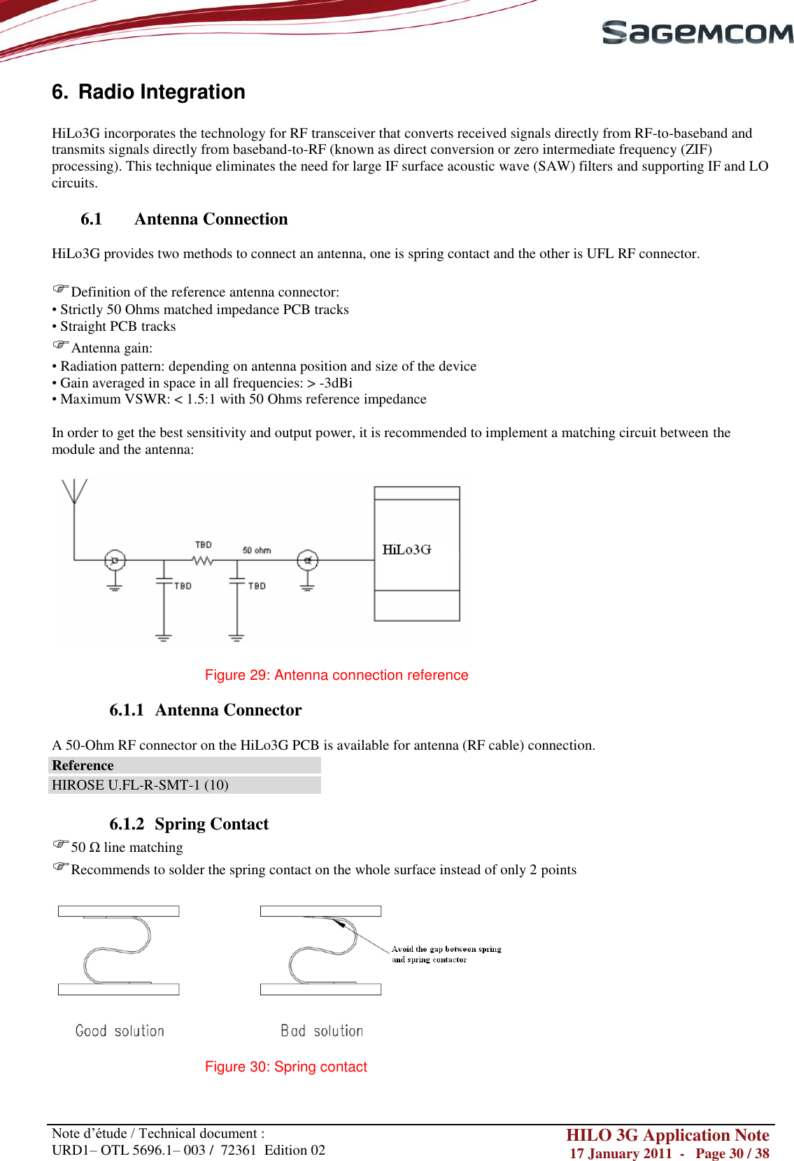
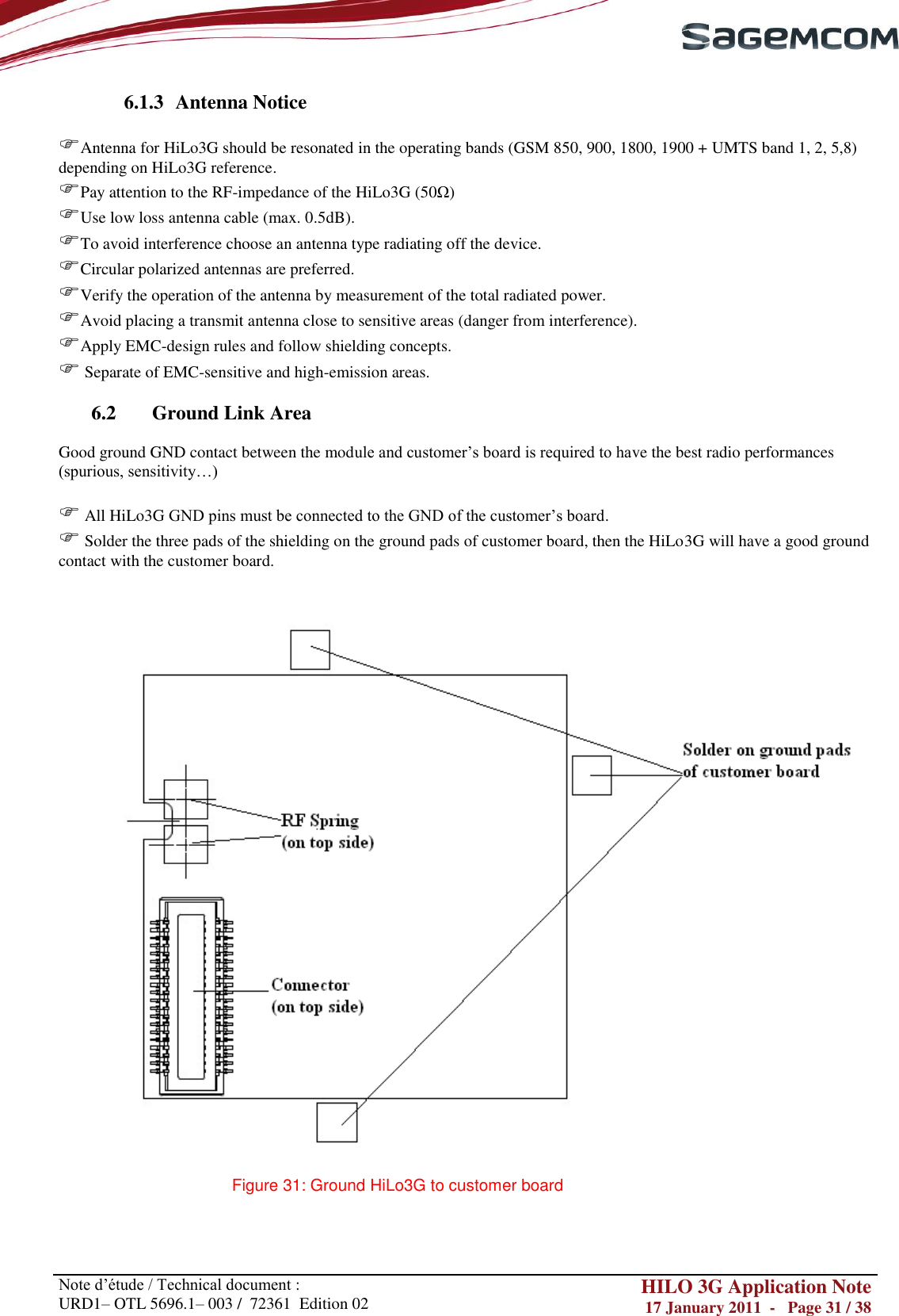
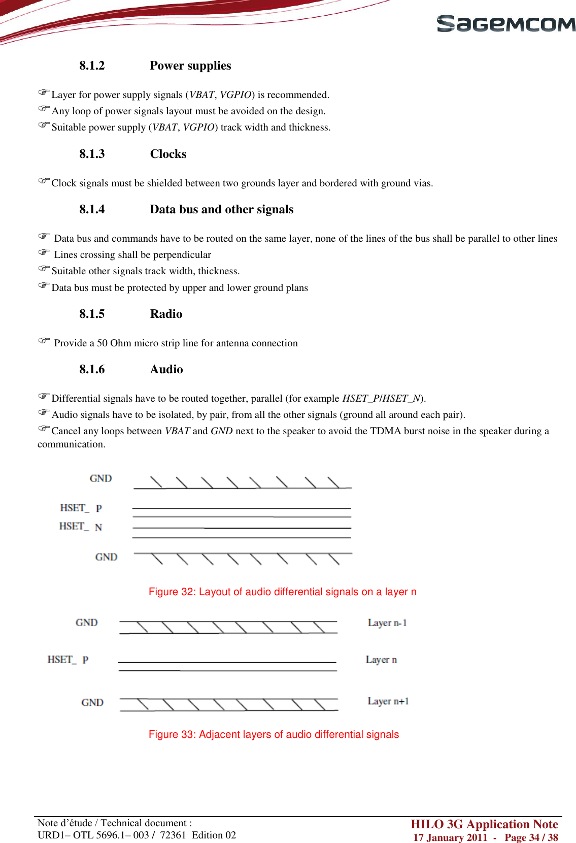
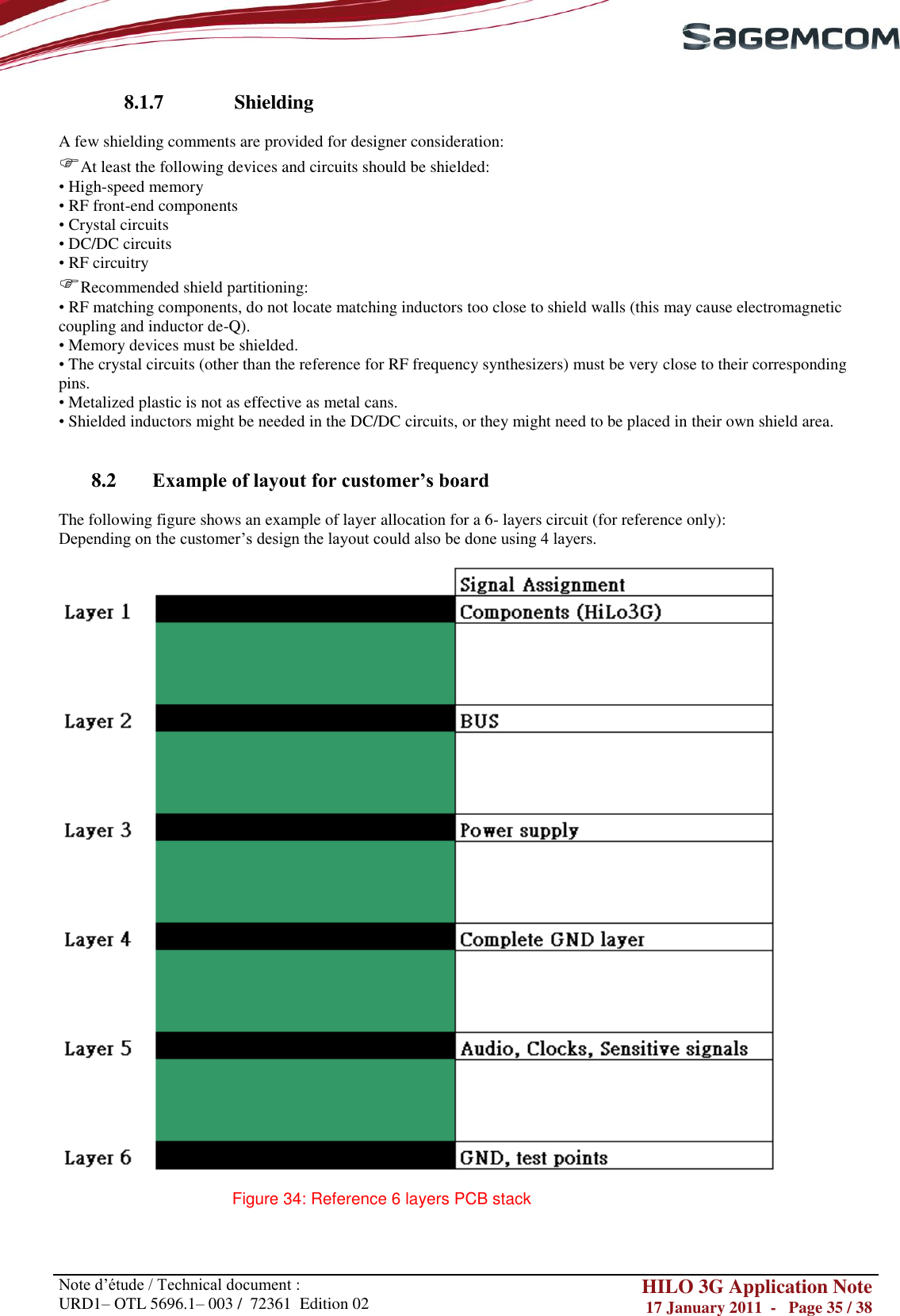
![Note d‘étude / Technical document : URD1– OTL 5696.1– 003 / 72361 Edition 02 HILO 3G Application Note 17 January 2011 - Page 6 / 38 1. OVERVIEW 1.1. Document Objectives The aim of this document is to describe some examples of hardware solutions for developing some products around the SagemCom HiLo3G Module. Most parts of these solutions are not mandatory. Use them as suggestions of what should be done to have a working product and what should be avoided thanks to our experience. This document suggests how to integrate the HiLo3G module into machine devices such as automotive, AMM (Automatic Metering Management), tracking system: connection with external devices, layout advises, external components (decoupling capacitors…), etc. 1.2. Reference Documents [1] URD1 OTL 5696.1 004 72362 Ed 04 - HiLo 3G technical specifications [2] URD1 OTL 5696.1 006 72370 Ed 01- AT Command Set for SAGEM HiLo3G Modules 1.3. Document Modifications The information presented in this document is supposed to be accurate and reliable. SAGEMCOM assumes no responsibility for its use, nor any infringement of patents or other rights of third parties which may result from its use. This document is subject to change without notice. Changes or modifications not expressly approved by the party responsible for compliance could void the user‘s authority to operate the equipment. 1.4. Conventions SIGNAL NAME: All signal names available on the pins of the HiLo3G module are written in italic. Specific attention must be granted to the information given here.](https://usermanual.wiki/SAGEMCOM-BROANDS/HILO3G/User-Guide-1414932-Page-6.png)