SAM Electronics 340X-RIK-93XX Automatic Identification System User Manual b ai e
SAM Electronics GmbH Automatic Identification System b ai e
User Instructions

Operating Instructions
Universal Automatic Identification System
UAIS DEBEG 3400
Display and Control Unit DEBEG 3401
Software Version 1.0
Item No.: ED 3047 G 122 Revision: – (2002-12) Order No.: 300005477

b_ai_eti.fm / 19.12.02
This document is our property for which we reserve all rights, including
those relating to patents or registered designs. It must not be
reproduced or used otherwise or made available to any third party without
our prior permission in writing.
Alterations due to technical progress are reserved.
STN ATLAS Marine Electronics GmbH
D - 22763 Hamburg
Service
Customer Support Center
Phone: + 49 (0) 18 03 00 85 53
Fax: + 49 (0) 18 03 00 85 54
E-mail: shipservice@sam-electronics.de

ED 3047 G 122 / – (2002-12)
Operating Instructions List of Contents
b_ai_eiv.fm / 19.12.02
3
DCU DEBEG 3401
List of Contents
List of Contents . . . . . . . . . . . . . . . . . . . . . . . . . . . . . . . . . . . . . . . . . . . . . . . . . . . . . . . . . . . . . 3
1Overview . . . . . . . . . . . . . . . . . . . . . . . . . . . . . . . . . . . . . . . . . . . . . . . . . . . . . . . . . . . . . . . . . . . . 5
2 General Remarks about Operating Procedures and Display . . . . . . . . . . . . . . . . 9
2.1 Switching the Display and Control Unit On and Off . . . . . . . . . . . . . . . . . . . . . . . . . . . . . . . 9
2.2 Situation Display and Target Data Display . . . . . . . . . . . . . . . . . . . . . . . . . . . . . . . . . . . . . . . 9
2.3 Menu and Dialogs . . . . . . . . . . . . . . . . . . . . . . . . . . . . . . . . . . . . . . . . . . . . . . . . . . . . . . . . . . . 10
2.4 Keyboard . . . . . . . . . . . . . . . . . . . . . . . . . . . . . . . . . . . . . . . . . . . . . . . . . . . . . . . . . . . . . . . . . . 11
2.5 Alarm Handling . . . . . . . . . . . . . . . . . . . . . . . . . . . . . . . . . . . . . . . . . . . . . . . . . . . . . . . . . . . . . 13
2.6 The Editor; Entering Numbers and Texts . . . . . . . . . . . . . . . . . . . . . . . . . . . . . . . . . . . . . . . 14
2.7 Setting the Brightness . . . . . . . . . . . . . . . . . . . . . . . . . . . . . . . . . . . . . . . . . . . . . . . . . . . . . . . 16
3 Target Handling . . . . . . . . . . . . . . . . . . . . . . . . . . . . . . . . . . . . . . . . . . . . . . . . . . . . . . . . . . . . 17
3.1 Display of the Targets in the Situation Display . . . . . . . . . . . . . . . . . . . . . . . . . . . . . . . . . . 17
3.2 Displaying Data of a Target in the Target Data Display . . . . . . . . . . . . . . . . . . . . . . . . . . . 17
3.3 Displaying Targets of Equipment Class B . . . . . . . . . . . . . . . . . . . . . . . . . . . . . . . . . . . . . . 18
3.4 Listing All Targets . . . . . . . . . . . . . . . . . . . . . . . . . . . . . . . . . . . . . . . . . . . . . . . . . . . . . . . . . . 19
4 AIS Messages . . . . . . . . . . . . . . . . . . . . . . . . . . . . . . . . . . . . . . . . . . . . . . . . . . . . . . . . . . . . . . 21
4.1 Receiving Safety Messages . . . . . . . . . . . . . . . . . . . . . . . . . . . . . . . . . . . . . . . . . . . . . . . . . . 21
4.2 Transmitting Safety Messages . . . . . . . . . . . . . . . . . . . . . . . . . . . . . . . . . . . . . . . . . . . . . . . . 22
4.2.1 Broadcasting a Message . . . . . . . . . . . . . . . . . . . . . . . . . . . . . . . . . . . . . . . . . . . . . . . . . . . . . . 22
4.2.2 Sending an Addressed Message . . . . . . . . . . . . . . . . . . . . . . . . . . . . . . . . . . . . . . . . . . . . . . . . 23
4.3 Long Range Interrogation . . . . . . . . . . . . . . . . . . . . . . . . . . . . . . . . . . . . . . . . . . . . . . . . . . . . 25
4.3.1 Setting of the Reply Mode . . . . . . . . . . . . . . . . . . . . . . . . . . . . . . . . . . . . . . . . . . . . . . . . . . . . . 26
4.3.2 The Alarm Long Range Interrogation . . . . . . . . . . . . . . . . . . . . . . . . . . . . . . . . . . . . . . . . . . . . 26
5 AIS Settings, Voyage Data and Other Displays . . . . . . . . . . . . . . . . . . . . . . . . . . . . . 27
5.1 Setting the Voyage Data . . . . . . . . . . . . . . . . . . . . . . . . . . . . . . . . . . . . . . . . . . . . . . . . . . . . . 27
5.2 Displaying Own AIS Data . . . . . . . . . . . . . . . . . . . . . . . . . . . . . . . . . . . . . . . . . . . . . . . . . . . . 28
5.3 Channel Management . . . . . . . . . . . . . . . . . . . . . . . . . . . . . . . . . . . . . . . . . . . . . . . . . . . . . . . 28
5.4 Switching Off the Transmitter . . . . . . . . . . . . . . . . . . . . . . . . . . . . . . . . . . . . . . . . . . . . . . . . . 30
5.5 Displaying the AIS State . . . . . . . . . . . . . . . . . . . . . . . . . . . . . . . . . . . . . . . . . . . . . . . . . . . . . 31
5.6 Determining the Versions of the Software . . . . . . . . . . . . . . . . . . . . . . . . . . . . . . . . . . . . . . 32
5.7 Built-in Test Equipment . . . . . . . . . . . . . . . . . . . . . . . . . . . . . . . . . . . . . . . . . . . . . . . . . . . . . . 32
Notes . . . . . . . . . . . . . . . . . . . . . . . . . . . . . . . . . . . . . . . . . . . . . . . . . . . . . . . . . . . . . . . . . . . . . . . 33

DCU DEBEG 3401
ED 3047 G 122 / – (2002-12)
Operating Instructions
List of Contents
b_ai_eiv.fm / 19.12.02
4
ED 3047 G 122 / – (2002-12)
Operating Instructions
1 Overview
b_ai_e01.fm / 19.12.02
5
DCU DEBEG 3401
1 Overview
AIS Summarised Briefly
The Universal Shipborne Automatic Identification System (AIS) automatically provides the ship's nautical
officers with important information about nearby vessels or other relevant objects within VHF range.
The AIS system transmits own ship data cyclically via two defined VHF channels and receives the same
data of the other ships and objects that are equipped with AIS systems. The VHF channels in use can
be switched over by external commands via the integrated DSC receiver.
Based on SOLAS Chapter V - Safety of Navigation, a carriage requirement will enter into force for
different categories of ships. This obligation will be introduced step by step for different ship classes and
sizes, commencing on 1st July 2002 (all new vessels) and continuing until 1st July 2008 (all ships world-
wide having gross tonnages of at least 500 tons, and ships sailing internationally with gross tonnages of
at least 300 tons, but by 1st July 2007 at the latest). In addition, other vessels or objects to which the
provisions of regulations do not apply may be equipped on a voluntary basis.
Depending on the number of equipped vessels the degree of nautical safety is increased by AIS.
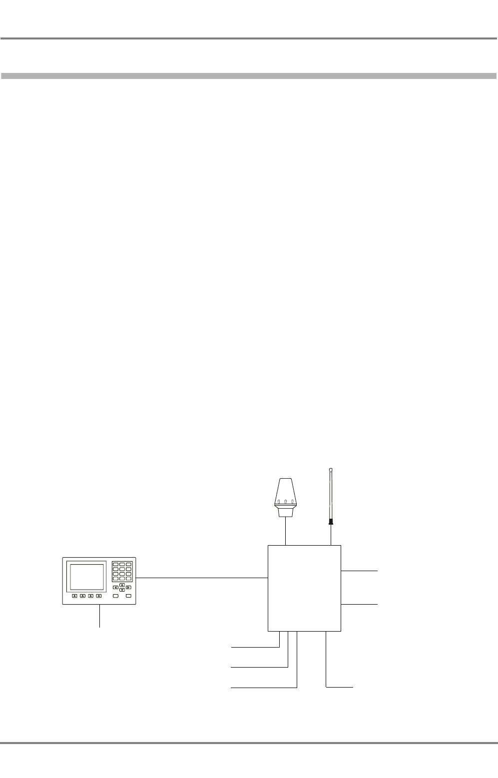
The System Components
The equipment described in these Operating Instructions is designed for installation on ships where such
installation is mandatory, and meets the relevant requirements. It consists of:
- the UAIS Electronics Unit DEBEG 3400, which contains complex electronics (including two VHF
transmitters, a DSC receiver, a GPS receiver and the data processor) but no operating or display
elements,
- the VHF antenna,
- the GPS antenna,
- the Display and Control Unit (DCU), on which the operating procedures described here take place,
connected to the Primary Display Port, and
- the 24 VDC power supply optionally connected to the ship’s emergency power supply which is
necessary for the Electronics Unit and DCU.
Display and
GPS antenna VHF antenna
Gyro
GPS
Log
Power supply
Long Range Port
Pilot Port
see page 7
see page 25
1 2 3
4 5 6
7 8 9
C
Menu
0Enter
On
Primary Display Port AIS
(24 VDC)
Power supply
(24 VDC)
Control Unit
Nav. Sensors
Electronics Unit
(DCU)
DCU DEBEG 3401
ED 3047 G 122 / – (2002-12)
Operating Instructions
1 Overview
b_ai_e01.fm / 19.12.02
6
Targets and AIS Objects
With regard to the objects that can be detected by the AIS system and whose data can be displayed, a
distinction is drawn between the following:
- Targets: ships that are equipped with an AIS system, divided into
- Class A targets: ships that are subject to the SOLAS Convention (see above)
- Class B targets: all other ships and boats, e.g. including pleasure craft
- SAR aircraft: search-and-rescue aeroplanes or helicopters
- Base stations: shore stations of the AIS system, e.g. traffic control centres
☞In the equipment described here, SAR aircraft are treated in much the same way as AIS Class A
targets, and are mentioned only in those cases where there are differences.
☞For simplification, this Operating Instructions uses the designation "target(s)" for all ships and objects
sending data via AIS.
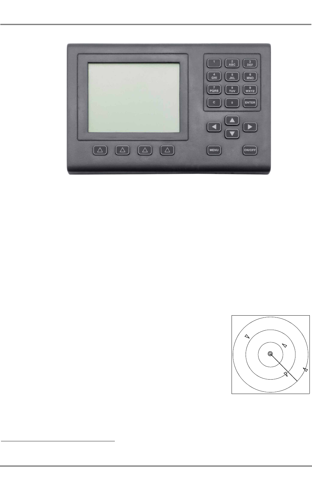
Situation Display
Targets and the own ship symbol can be displayed in a Situation
Display. The triangular symbols indicate the headings of the targets.
In addition to the Situation Display, it is also possible to display the
data received from a target (e.g. its position, course, speed, heading,
name, destination etc.), as well as data determined by the DCU rela-
tive to the own ship (range, bearing) - see Section 3.2.
Safety Messages and Long Range Interrogation
Via the, Safety Messages 1) can be communicated if necessary, which
are then passed on by all receiving AIS systems as a message or an
alarm to their display units. The procedures for dealing with the Safety
Messages received, and for transmitting your own Safety Messages,
are described in Section 4.1 and 4.2.
1) Also called Safety Related Messages in the relevant regulations.
The Display and Control Unit (DCU)
Situation Display:
Own ship with heading line,
targets and range rings

ED 3047 G 122 / – (2002-12)
Operating Instructions
1 Overview
b_ai_e01.fm / 19.12.02
7
DCU DEBEG 3401
The AIS system can also be interrogated about ship data by an (external) system, e.g. via a SatCom
system. Details of this are described in Section 4.3.
Monitoring/Setting of the Own Ship Data Transmitted
Most of the information transmitted from your own AIS system is generated automatically by the system.
The navigation data necessary for this are received by the AIS system from the connected sensors (e.g.
gyro, log, GPS receiver). However, some items of information (e.g. ship's draught, hazardous cargo,
destination, ETA) have to be defined by the operator - see Section 5.1.
IMPORTANT
Because these data are voyage-dependent, their updating by the respon-
sible navigator should be assured by including them in the Navigational
Check List.
Setting of the communication technique (channel selection, bandwidth, transmission power etc.) usually
takes place fully automatically. In very rare cases, however, manual setting procedures too might be
necessary for this channel management process. For details, see Section 5.3.
Other Operating Possibilities; Pilot Port
The AIS system has yet another interface, called the "Pilot Port", by means of which e.g. the pilot
connects a device of his own, from which he can operate the AIS system and can read the desired data.
Scope of Applicability of these Operating Instructions
These Operating Instructions refer to the Display and Control Unit DEBEG 3401 which is approved under
the software version stated on the title page in conjunction with the UAIS Electronics Unit DEBEG 3400.
The Pilot Port has the same functions as the Primary Display Port.
☞On page 32, there is a description of how the software version of the DCU can be displayed.

DCU DEBEG 3401
ED 3047 G 122 / – (2002-12)
Operating Instructions
1 Overview
b_ai_e01.fm / 19.12.02
8
ED 3047 G 122 / – (2002-12)
Operating Instructions
2 General Remarks about Operating Procedures and Display
2.1 Switching the Display and Control Unit On and Off
b_ai_e02.fm / 19.12.02
9
DCU DEBEG 3401
2 General Remarks about Operating Procedures and Display
The AIS Electronics Unit continually broadcasts the own ship data (i.e. position, speed, course etc.) which
can be received by all other AIS stations in VHF range.
The information is displayed on the Display and Control Unit DCU. The Electronics Unit and the DCU
are independent of each other i.e. the Electronics Unit will work (send and receive) even when the DCU
is switched off.
Other installations are available, where the radar system or the ECDIS is used as display and operating
unit for the AIS functions.
2.1 Switching the Display and Control Unit On and Off
Switching the DCU on and off is done by pressing the ON/OFF key.
☞At the instant of switching on, the brightness setting that existed when the unit was
switched off last is taken over. Therefore, it can happen that, after switch-on, the
display remains dark and the keys are not lit up. Therefore, in a dark room it is then
not possible to recognise that the unit is in the switched-on state. The display can be
made brighter by pressing the 0 key; see also Section 2.7.
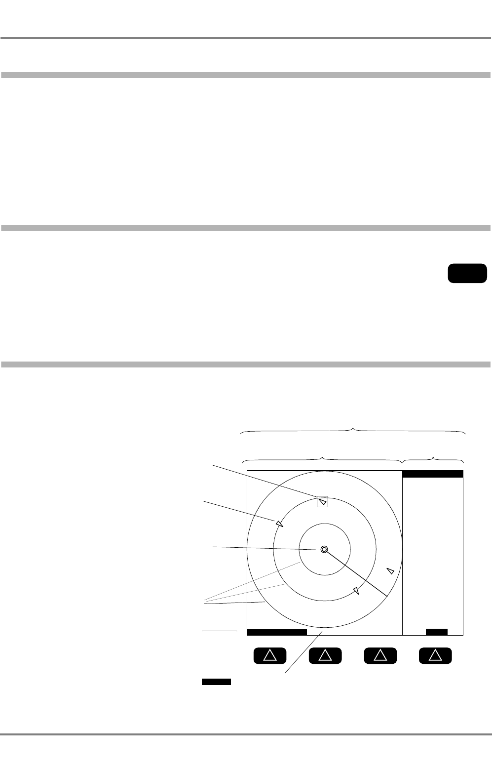
2.2 Situation Display and Target Data Display
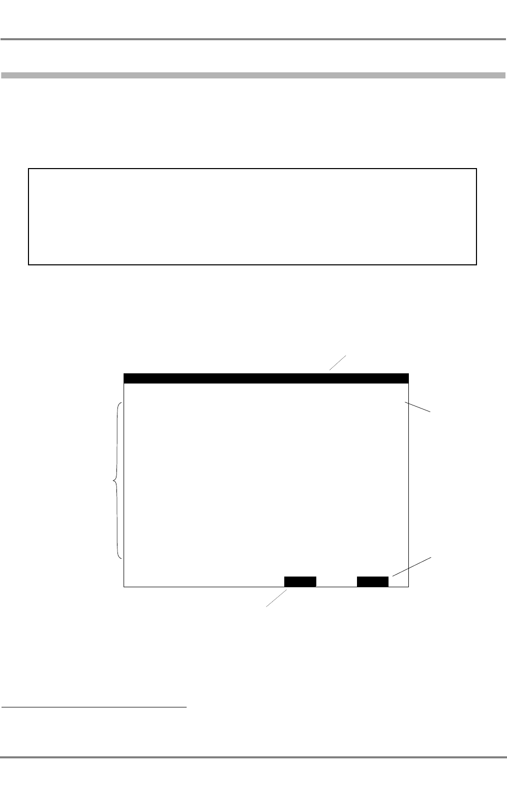
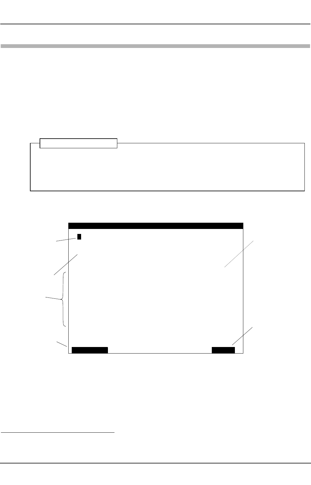
Shortly after switching on, the operational display appears in the Display Area, showing the Situation
Display and the Target Data Display:
ON/OFF
Target Data DisplaySituation Display
RANGE 12NM
When an alarm occurs, the function appears here.
Pressing the key below it, opens the alarm list
ALARM
Functions of the softkeys that are situ-
ated below
Target
Own ship symbol (always at the
centre of the Situation Display)
Marking of the target whose data appear
in the Target Data Display
Range Rings
MORE
>1°/min
306.8°
HDG/ROT
15.7kt
COG/SOG
BRG/RNG
16:38.00
321.6°
356.2°
034:11.35
7.2NM
POSITION
VEN
275635812
DTEH2
MS BREMERHA
Class
TARGET DATA
Display Area
A
N
W
DCU DEBEG 3401
ED 3047 G 122 / – (2002-12)
Operating Instructions
2 General Remarks about Operating Procedures and Display
2.3 Menu and Dialogs
b_ai_e02.fm / 19.12.02
10
In the Situation Display, the own ship symbol and the target symbols are displayed at the correct posi-
tions in north-up display mode. The target symbols each indicate the heading of the target (ship). The
own ship symbol is always situated at the centre of the display. For details, see Section 3.1.
After switch-on, the Target Data Display first shows the own ship data. It is then possible to display the
data received from each target, one target at a time; for details, see Section 3.2.
☞The target data are transferred at defined time intervals. The interval between transfers depends on
the speed and rate of turn of the target: for the data from which the DCU generates the target
symbols, the interval lies between 2 seconds (the target speed exceeding 23 kt) and 3 minutes
(when lying at anchor).
Setting the range: With the left-hand key of the keys situated under the display, set the desired range
(1.5, 3, 6, 12 or 24 NM) by pressing that key (several times if necessary). The radius of the outer Range
Ring corresponds to the set value.
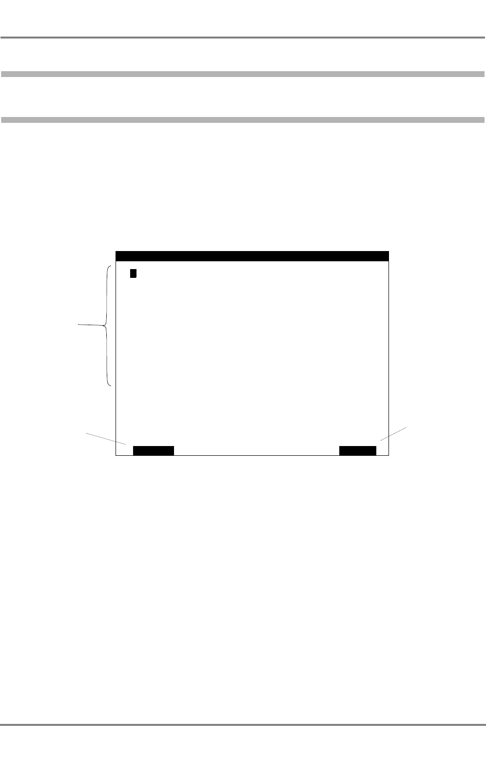
2.3 Menu and Dialogs
The default information displayed on the DCU consists of the Situation Display and the Target Data
Display. All other data displays and operating procedures take place in the various dialogs which can be
operated via the menu.
☞The menu covers the Target Data Display; dialogs take up the entire display area.
Showing a dialog: By pressing the MENU key, switch on the menu; in the menu, mark the desired dialog
by means of the ArrowUp/ArrowDown keys, and press the ENTER key.
Switching off the dialog display: This is done in different ways in the various dialogs, depending upon
whether data inputs can take place in the dialogs or whether only pure displays are involved.
In addition to these specific methods described in the following sections, a dialog can always 1) be
switched off by pressing the MENU key. Dialogs in which data inputs are possible are aborted by this
action, i.e. data that have been entered are not taken over.
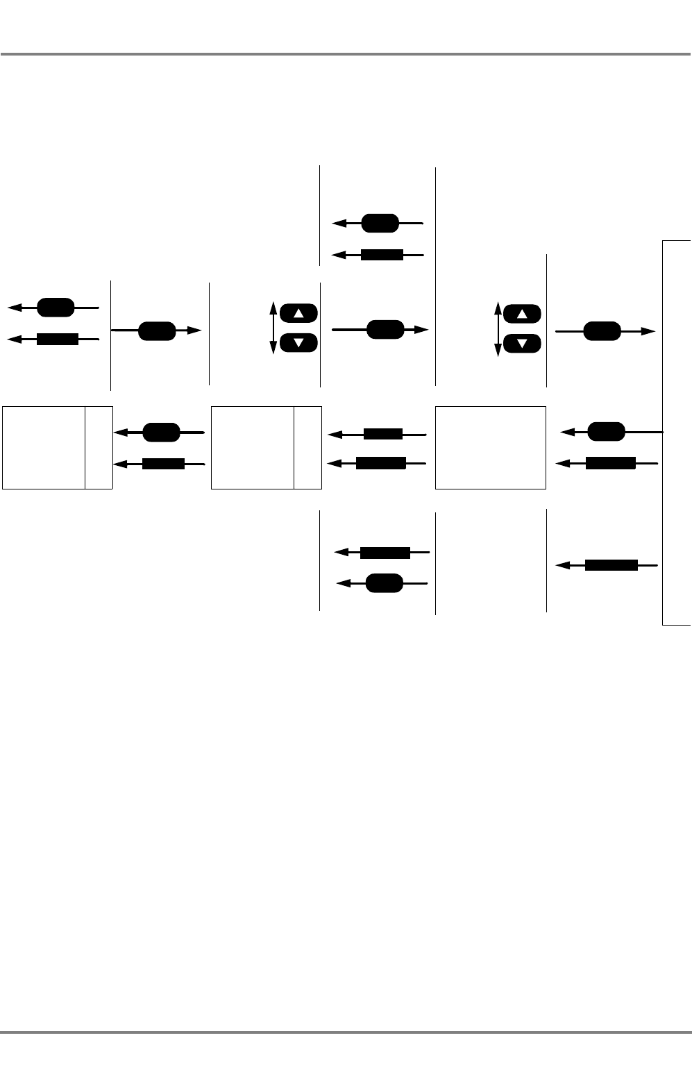
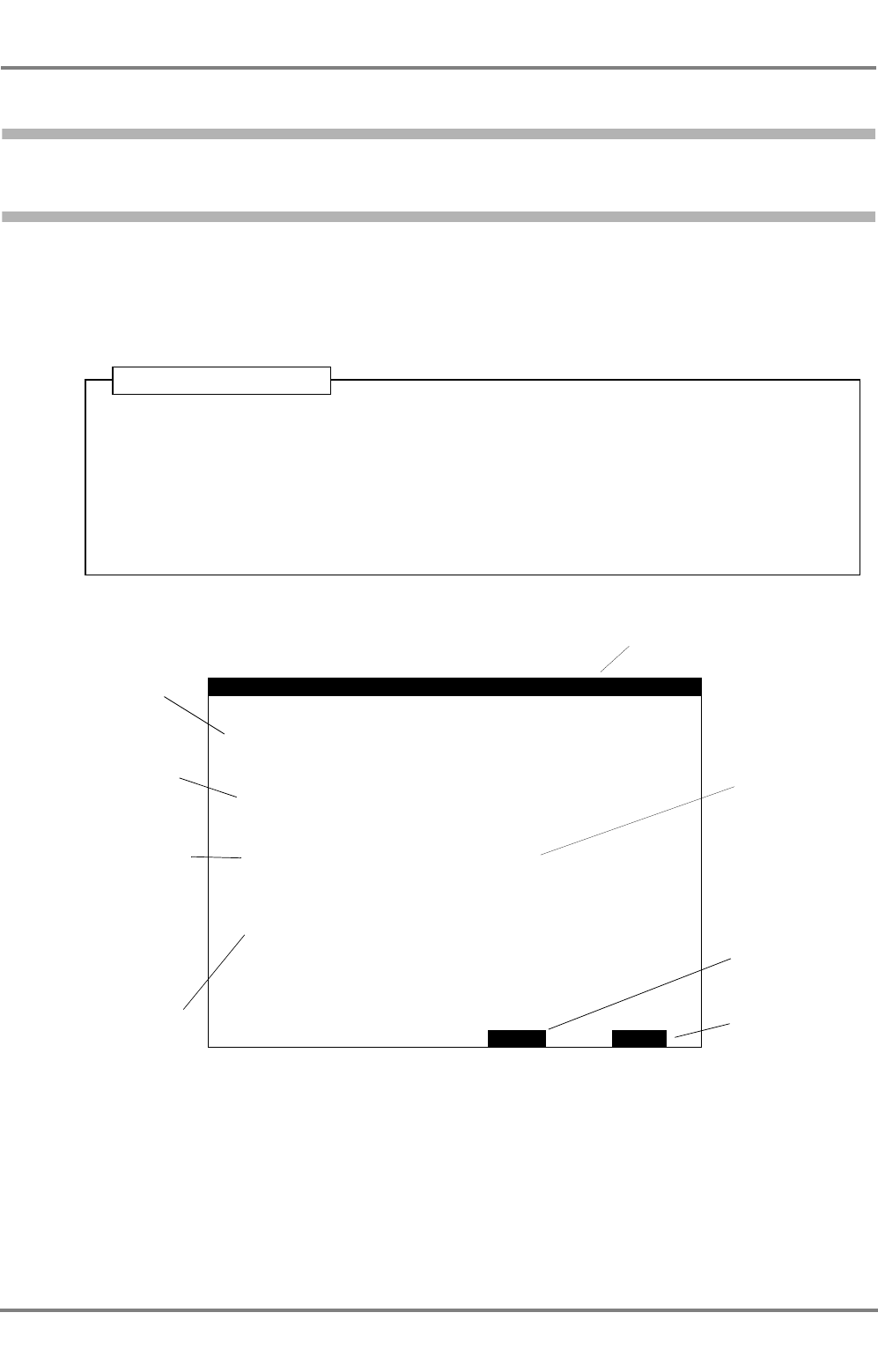
The Menu
1) But not during editing
The marker is
set by means of
the ArrowUp/
ArrowDown
keys
MENU
VOYAGE
>
READ
CONFIG
INTERROGAT
ALARM
CHANNEL
TGT
SEND
LIST
SETTINGS
MSG.
MSG.
STATE
BACK
LIST
When this menu position is marked, the following dialog
is opened with ENTER:
TARGET LIST - see Section 3.2
ALARM LIST - see Section 2.5
READ SAFETY MESSAGE - see Section 4.1
SEND SAFETY MESSAGE - see Section 4.2
LONG RANGE INTERROGATION - see Section 4.3
VOYAGE DATA - see Section 5.1
CHANNEL MANAGEMENT - see Section 5.3
AIS STATE - see Section 5.5
SETTINGS - see Section 2.7
CONFIGURATION - see Section 5.6
Switches the menu off
ED 3047 G 122 / – (2002-12)
Operating Instructions
2 General Remarks about Operating Procedures and Display
2.4 Keyboard
b_ai_e02.fm / 19.12.02
11
DCU DEBEG 3401
2.4 Keyboard
The keyboard consists of the following areas:
Alphanumeric Keyboard
With this keyboard, numerical values and texts can be entered (edited)
in particular fields of the dialogs. For details of editing, see Section 2.6.
In addition, the ENTER key has special significance. Generally, it acti-
vates a marked function:
- In the Situation Display, the data of the marked target or marked
own ship are displayed.
- In the menu, the marked dialog is called up.
- In the dialog, the marked field is opened for editing.
- In the case of editing, the changes made in this field by editing are
put into intermediate storage and this editing field is closed.
The 0 key too has another function over and above the editing function:
it can be used to set the illumination of the display without opening the
respective dialog- see Section 2.7.
Arrow Keys
With these, a selection can be made:
- In the Situation Display, a target or own ship is marked with the aid
of the four keys.
- In the menu, these keys are used to mark the dialog to be opened.
In the dialogs, they are used to mark the field that is to be edited.
During this process, the ArrowUp/ArrowDown keys make the
marker jump to the previous or next field that can be marked, and
(in most dialogs) the ArrowRight/ArrowLeft keys make the marker
jump to the bottom or top field that can be marked.
- In particular editing fields, the ArrowUp/ArrowDown keys can be
used to change the value or to select one of the possible entries.
☞In these cases, the message Use arrow keys appears in the
dialog.
- In the other editing fields, the ArrowRight/ArrowLeft keys can be
used to change the position of the editing cursor.
The Softkeys
The four keys situated below the display possess functions which
depend on the operating situation. The function involved is shown
inverted in the bottom line of the display. These functions are explained
in the individual sections of these Operating Instructions.
The MENU Key
With this key, the menu is switched on and off. If there is a dialog open,
this key aborts it. In the case of editing, the MENU key has no effect.
ENTER
0
MENU
DCU DEBEG 3401
ED 3047 G 122 / – (2002-12)
Operating Instructions
2 General Remarks about Operating Procedures and Display
2.4 Keyboard
b_ai_e02.fm / 19.12.02
12
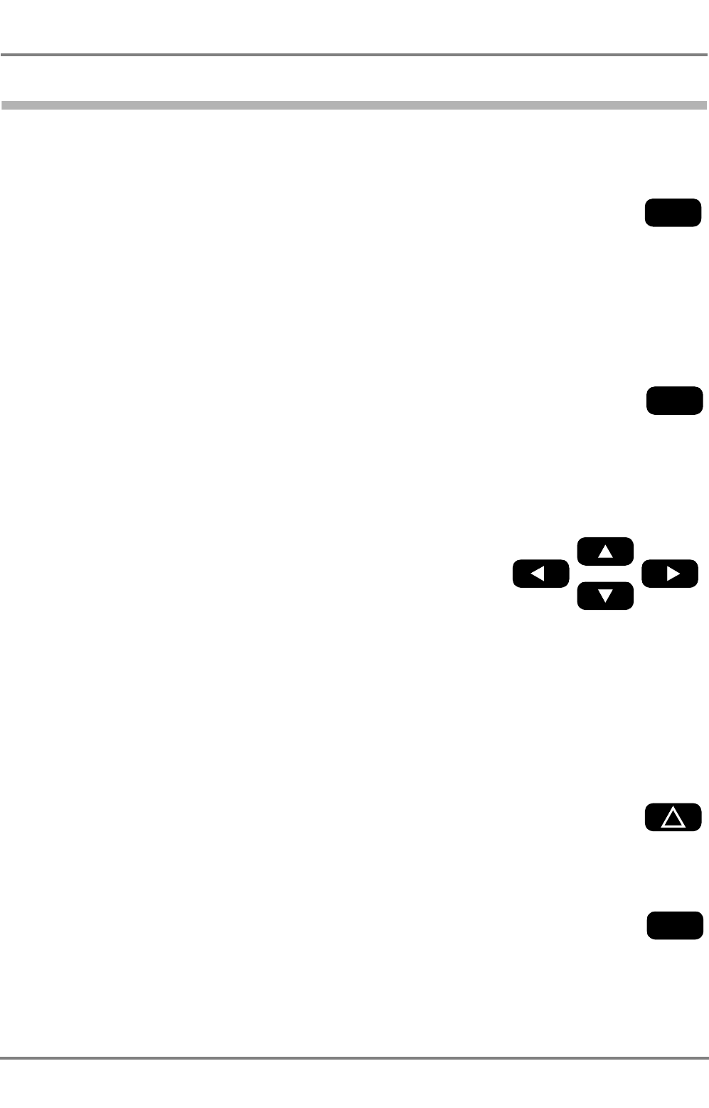
Summary
For the opening and closing of the dialogs and of the editing fields, the statements made above can be
summarised schematically as follows:
Situation Display
Target data
Menu
Dialog
MENU
MENU
ENTER ENTER
ENTER
Editing
Marking Marking the
into intermediate
Aborting:
Aborting:
Change
Situation Display
the dialog
takes effect:
editing field
or
Putting the change
BACK
ABORT
or
SEND
APPLY
ABORT
or
STORE
MENU
or
storage:
Dialog without
editing fields:
MENU
or
BACK
MENU
or
BACK
ED 3047 G 122 / – (2002-12)
Operating Instructions
2 General Remarks about Operating Procedures and Display
2.5 Alarm Handling
b_ai_e02.fm / 19.12.02
13
DCU DEBEG 3401
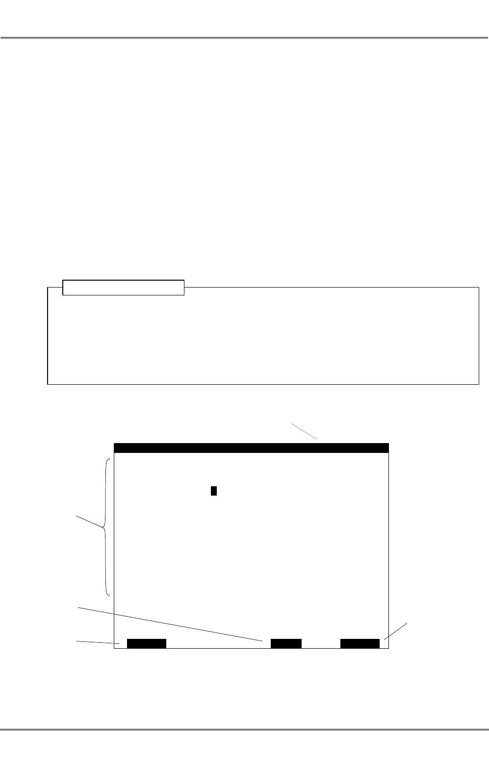
2.5 Alarm Handling
When a Safety Message or a Long Range Interrogation is received, for example, or if a technical fault
occurs, an alarm will be displayed.
Alarm handling is identical for all alarms:
The ALARM LIST dialog can also be viewed at any time irrespective of the occurrence of an alarm:
1. When an alarm occurs, a softkey acquires the function ALARM.
2. After this softkey is pressed, the dialog ALARM LIST and the alarm message will be
displayed.
If further alarms exist that have not yet been acknowledged or if the causes of acknowl-
edged alarms still exist, these alarm messages are likewise contained in the list. Alarms
that have not yet been acknowledged are indicated with not in the ACK column.
3. By pressing ACKNOWLEDGE, the selected alarm will be acknowledged. This is normally
the alarm on top of the list. Other alarms can be selected by pressing the arrow keys.
To leave the alarm list, BACK has to be pressed.
Operating Sequence
ALARM
ALARM ACK
MESSAGE
Chronological list
of alarms that
occur, with the
most recent
alarm message
at the top
not: Alarm has not yet been
acknowledged
yes: Alarm has been acknowl-
edged
– : Alarm is not acknowledg-
able
Acknowledges
the alarm
marked with
>
Closes the alarm list
not
ACKNOWLEDGE
>New safety message
BACK
LIST 1/1
yesTarget display overflow
1. Press MENU.
2. In the menu, mark ALARM LIST by means of the ArrowUp/ArrowDown keys and press
ENTER.
Back: Press BACK twice.
Operating Sequence

DCU DEBEG 3401
ED 3047 G 122 / – (2002-12)
Operating Instructions
2 General Remarks about Operating Procedures and Display
2.6 The Editor; Entering Numbers and Texts
b_ai_e02.fm / 19.12.02
14
List of Alarm Messages
Channel management changed:see page 28
Long range interrogation:see page 26
New safety message:see page 21
Safety msg transmission failed: see page 24
Target display overflow:see page 17
Target overflow:see page 19
If other alarms appear, they indicate technical faults; see also page 32.
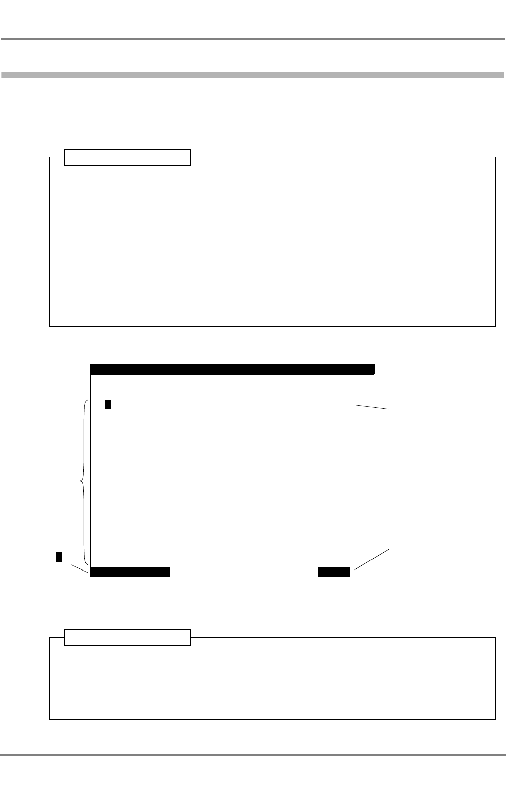
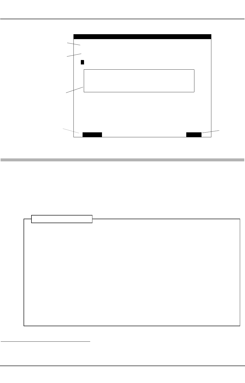
2.6 The Editor; Entering Numbers and Texts
Dialog fields whose content can be edited can be marked with the prefixed character by means of the
arrow keys.
In general:
- For data input press ENTER. The field to be edited is marked by means of a frame.
- During data input, pressing ENTER causes take-over (intermediate storage) of the content and
closing of the editing field.
- During data input, pressing ABORT causes rejection of the content and closing of the editing field.
The previous content is inserted again.
Other possibilities for changing the content of the editing field are:
Selection Fields
These fields can be recognised from the fact that the message Use arrow keys appears in the line above
the softkey names.
With the ArrowUp/ArrowDown keys, you can select between the possible settings.
Numerical Input Fields
In the editing field that is open, the (flashing) editing cursor indicates the place at which input takes place
by means of the numerical keyboard.
With the C key, the character at the cursor position is replaced by a blank (Clear function).
With the ArrowRight/ArrowLeft keys, the position of the editing cursor can be changed.
With CLEAR ALL, the content of the editing field is deleted.
Fields for Text Input
The editing possibilities are the same as for the numerical fields.
By the pressing of an alphanumeric key, the first of the letters shown on the key is written first of all. By
the pressing of this key repeatedly in rapid succession, the other characters can be written instead.
The blank and the characters . , ? : " ( ) 0 are entered with the key 0.
The characters - + = > < @ 1 are entered with the key 1.

ED 3047 G 122 / – (2002-12)
Operating Instructions
2 General Remarks about Operating Procedures and Display
2.6 The Editor; Entering Numbers and Texts
b_ai_e02.fm / 19.12.02
15
DCU DEBEG 3401
DATA
CLEAR ALLABORT
DRAUGHT:
PERSONS
STATE:
TYPE:
ETA:
DESTINATION:
Under
Cargo
VOYAGE
ON BOARD:
BREM
13
category A
way using engine
23
6.5m
Oct 23:30 UTC
Frame indicates the
opened editing field
A dialog during editing
The editing cursor
Deletes the entire
content of the opened
editing field
Closes the editing
field and enters the
old text again.
DCU DEBEG 3401
ED 3047 G 122 / – (2002-12)
Operating Instructions
2 General Remarks about Operating Procedures and Display
2.7 Setting the Brightness
b_ai_e02.fm / 19.12.02
16
2.7 Setting the Brightness
The background illumination of the display and of the keyboard can be set separately. The setting proce-
dure is performed in the SETTINGS dialog by means of the ArrowUp/ArrowDown keys in the fields
KEYBOARD BRIGHTNESS and DISPLAY BRIGHTNESS.
If the display is dimmed too dark it can be illuminated again by pressing the 0 key.
1. Press MENU.
2. In the menu, mark SETTINGS by means of the ArrowUp/ArrowDown keys and press
ENTER.
3. In the SETTINGS dialog, mark the field KEYBOARD BRIGHTNESS or DISPLAY
BRIGHTNESS by means of the ArrowUp/ArrowDown keys and press ENTER.
4. Set the brightness by means of the ArrowUp/ArrowDown keys and press ENTER.
Back: Press BACK twice.
Operating Sequence
SETTINGS
BACK
>
DISPLAY
KEYBOARD
DISPLAY CLASS B
BRIGHTNESS:
BRIGHTNESS:
TARGETS: On
1
9
Switches the display of
Equipment Class B on and off
- see Section 3.3
Setting the display
brightness
Setting the keyboard
brightness
TRANSMITTER COMPLETELY: On
Switches the transmitter on
and off - see Section 5.4
ED 3047 G 122 / – (2002-12)
Operating Instructions
3 Target Handling
3.1 Display of the Targets in the Situation Display
b_ai_e03.fm / 19.12.02
17
DCU DEBEG 3401
3 Target Handling
3.1 Display of the Targets in the Situation Display
When a target enters the range of the Situation Display, it appears there as a sharply
pointed triangle. The orientation of the symbol indicates the heading of the target.
In the Situation Display, a maximum of 30 targets can be displayed simultaneously. If
the Electronics Unit is receiving data from more than 30 targets, the 30 targets nearest
to own ship are displayed (provided that they are situated within the range shown by
the Situation Display) and the alarm Target display overflow appears.
Targets, not displayed graphically can be accessed via the Target List.
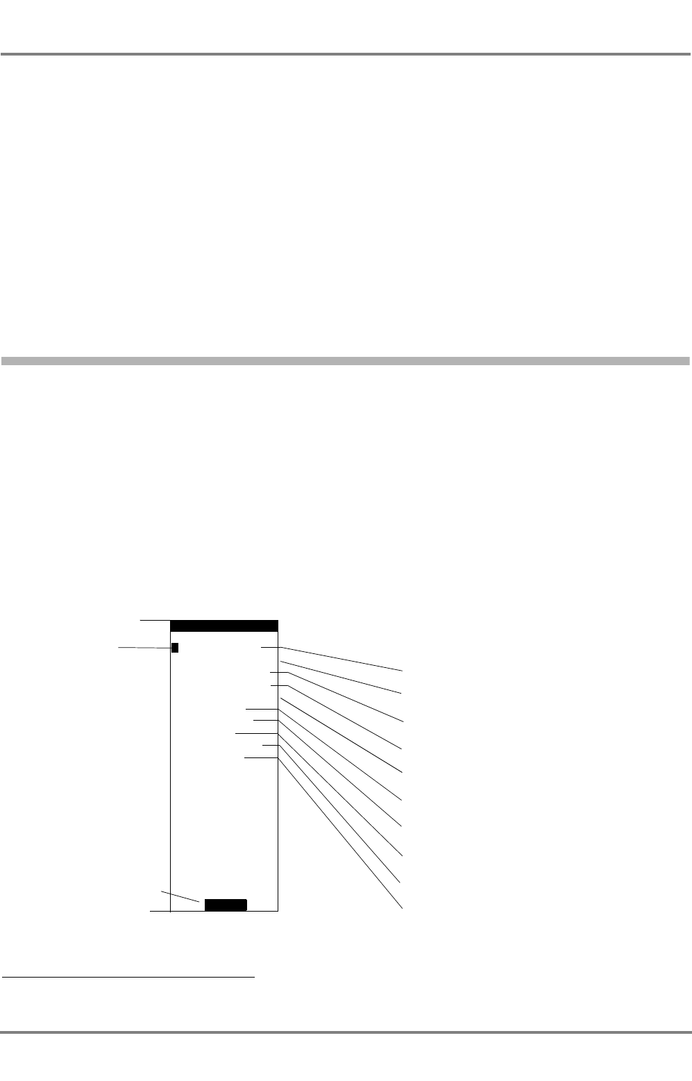
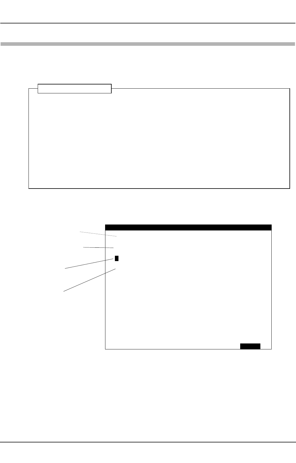
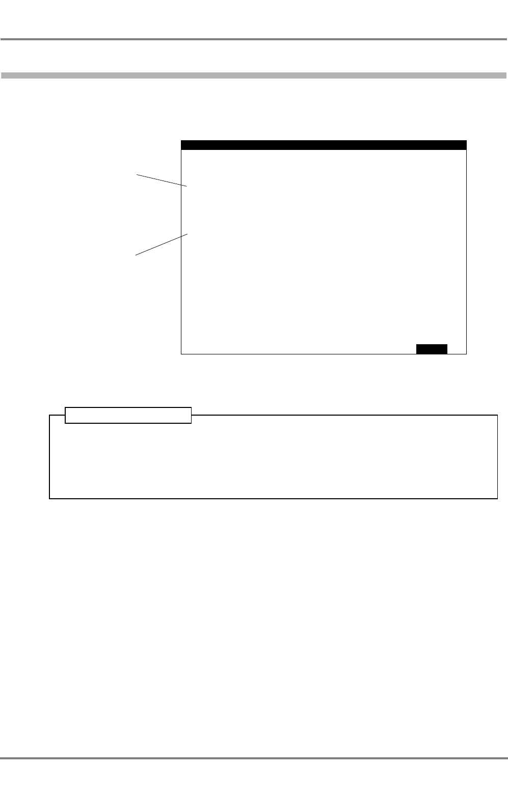
3.2 Displaying Data of a Target in the Target Data Display
Except the menu or a dialog is displayed, the data of a target (or own AIS data) are
shown in the Target Data Display.
In the Situation Display, the selected target (or own ship) display is marked with an
additional square.
Initially, the first data page of the selected target is displayed. The change-over to the second data page
and back again takes place with MORE.
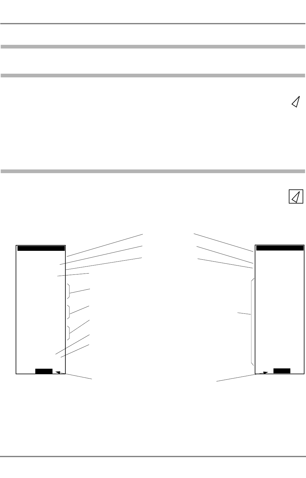
Page 1 of the Page 2 of the
Call sign of the target
Name of the target
MMSI No. of the target
Target position 1)
Bearing and range to the target 2)
Course over ground and speed
over ground of the target 1)
1) determined dynamically aboard the target
2) computed by the own AIS system
3) If no approved ROT indicator is being used the ROT is not indicated.
Heading 1)
Changes over between page 1 and 2 of the target data
Voyage data of the
target; for explana-
tions, see input of
own voyage data
in Section 5.1
target data
target data
MORE
>3°/min
256.8°
HDG/ROT
15.7kt
COG/SOG
BRG/RNG
16:38.00
321.6°
222.2°
034:11.35
22.2NM
POSITION
VEN
275635812
DTEH2
MS BREMERHA
Class A
TARGET DATA
Equipment class of the target
MORE
DRAUGHT
145m
LENGTH
Restricted
Cargo
ETA
BUENOS AIR
275635812
DTEH2
MS
22:22
ES
TYPE 003:
7.5m
DESTINATION
BREMERHA
MAR 07
UTC
manoeuvra
A
bility
type
TARGET DATA
STATE
N
W
VEN
Rate of Turn of the target 1) 3)
> = turning to STB
< = turning to PRT
In the case of SAR aircraft,
the altitude instead appears here 1)

DCU DEBEG 3401
ED 3047 G 122 / – (2002-12)
Operating Instructions
3 Target Handling
3.3 Displaying Targets of Equipment Class B
b_ai_e03.fm / 19.12.02
18
To specify the source of the data that are to be displayed, there are two possible operating procedures:
Selection by means of the ENTER key:
By repeated pressing of ENTER, the displayed targets (and own ship) are marked one after another and
the corresponding data are displayed.
Selection by means of arrow keys:
Press one of the arrow keys. As a result, the cursor appears in the Situation Display. The point of inter-
section between both lines is cursor position. To select the target move the cursor to the target by means
of the arrow keys, and press ENTER.
☞If the interval between the pressing of the keys is longer than 5 seconds, the cursor disappears.
3.3 Displaying Targets of Equipment Class B
The display of the Class A targets (ships to which the provisions of the SOLAS Convention apply) is
always switched on and cannot be deactivated.
Class B targets too (ships to which the provisions of the SOLAS Convention not apply and which are
equipped with an AIS system) can be displayed.
Switching the display of Class B targets on and off is done in the SETTINGS dialog, in the field DISPLAY
CLASS B TARGETS.
The restricted number of displayable targets includes also Class B targets i.e. thus, when the Class B
targets are switched on, this can make Class A targets disappear from the displays. Depending on the
nautical situation it may be recommendable to deselect the Class B targets.
1. Press MENU.
2. In the menu, mark SETTINGS by means of the ArrowUp/ArrowDown keys and press
ENTER.
3. In the SETTINGS dialog, mark the field DISPLAY CLASS B TARGETS by means of the
ArrowUp/ArrowDown keys and press ENTER.
4. Set the entry to On or Off by means of the ArrowUp/ArrowDown keys and press
ENTER.
Back: Press BACK twice.
Operating Sequence
ED 3047 G 122 / – (2002-12)
Operating Instructions
3 Target Handling
3.4 Listing All Targets
b_ai_e03.fm / 19.12.02
19
DCU DEBEG 3401
3.4 Listing All Targets
All targets from which data are being received are listed in the dialog TARGET LIST. In that list, not only
the name 1) but also the range, bearing and equipment class of each target are stated.
If data are being received from more than 15 targets, the list is organized in pages. Tur over the pages
by means of NEXT.
The maximum length of the Target List is limited to 300 targets. If more targets than that are received,
the alarm Target overflow appears.
1) If the target is not transmitting the ship's name (because that name has not been entered as voyage data - see Section 5.1), the MMSI
number of the target appears here.
Operating Sequence
1. Press MENU.
2. In the menu, mark TGT LIST by means of the ArrowUp/ArrowDown keys and press
ENTER.
Back: Press BACK.
NAME OR MMSI BRG CLASS
TARGET
BACK
Equipment class
of the target
All targets from
which data are
being received
Back to the menu
NEXT
MS 245° A
MS 036° A
223782659 013° B
MS 345° A
MS 235° A
MS A
TMS 311° A
MS 022° A
272839973 320° A
MS 274° A
MS 267° A
MS 046° A
MS 156° A
MS 026° A
337289165 167° B
189°
ETAGAS
RHONESTEIN
PURPLE
PACIFIC
MERCS
MARITTIMA
DIAMOND
MEKONG
GRACE
ORION
SUNBAY
BEACH
DISCOVERY
KOMARI
WELLS
STAR
CHURCH METE
MEKONG
RNG
6.3NM
0.9NM
11.6NM
4.8NM
3.9NM
22.1NM
16.1NM
2.8NM
14.6NM
0.5NM
2.6NM
1.3NM
4.8NM
16.9NM
5.4NM
LIST 1/8
1/5 = page 1 of 8
Page selection
NEXT exists only if more than 15
targets are being received

DCU DEBEG 3401
ED 3047 G 122 / – (2002-12)
Operating Instructions
3 Target Handling
3.4 Listing All Targets
b_ai_e03.fm / 19.12.02
20
ED 3047 G 122 / – (2002-12)
Operating Instructions
4 AIS Messages
4.1 Receiving Safety Messages
b_ai_e04.fm / 19.12.02
21
DCU DEBEG 3401
4 AIS Messages
4.1 Receiving Safety Messages
When the AIS system receives a Safety Message from another ship or base station, the alarm New
safety message appears.
After the alarm acknowledgement, the received message is displayed in the dialog READ SAFETY
MESSAGE, together with the identification data of the sender.
Display of the Messages Received Last
The last received five Safety Messages can be displayed. Switch-over is performed by means of NEXT.
Messages that have not yet been displayed are marked (new). Messages which have already been
displayed are marked (known).
☞If several messages have been received before the alarm list is opened, no alarm repetition takes
place for the messages which have already been viewed in this way.
1. Press ALARM.
2. In the dialog ALARM LIST, acknowledge the marked alarm-message New safety
message by pressing ACKNOWLEDGE.
As a result, the dialog READ SAFETY MESSAGE opens up, in which the received
message is displayed together with the identification data of the sender.
Back: Press BACK twice.
Operating Sequence
READ
BACKNEXT
721562451
CALLSIGN:ADRF1 MS HAVARIA MMSI:
GROUNDING LAT:50:58.231 N LON:00
14.0NM
NAME
CALL
MMSI
1:17.435 E TIME:DEC 17 13:11 UTC
BEARING
POSITION
MESSAGE:
LON
SAFETY MESSAGE
375289351
DRSTZ
MS BREMEN
LAT 50:08.357
006:46.735
RANGE 082°
N
E
Identification data
of the sender
Data at the time
when the message
was received
Content of the
Safety Message Back to the menu
Page selection
between the five
Safety Messages
received last
BROADCAST
Statement of whether
the message was
broadcast generally
(BROADCAST
MESSAGE) or was
sent to your ship only
(ADDRESSED
MESSAGE)
(new): Message
has not yet been
displayed
(known): Message
has already been
displayed
(new)
1/5
SIGN
1/5 = message 1 of 5

DCU DEBEG 3401
ED 3047 G 122 / – (2002-12)
Operating Instructions
4 AIS Messages
4.2 Transmitting Safety Messages
b_ai_e04.fm / 19.12.02
22
The dialog READ SAFETY MESSAGE can also be viewed at any time irrespective of the occurrence of
a new safety message:
4.2 Transmitting Safety Messages
If necessary, a Safety Message can be transmitted to targets, SAR aircraft and base stations. This Safety
Message is a freely edited text (max. 160 characters per message). The message can be broadcast
generally or transmitted to a particular AIS object.
4.2.1 Broadcasting a Message
In the SEND SAFETY MESSAGE dialog, set the entry TO ALL to On, edit the message in the message
field, and send the message by pressing SEND.
1. Press MENU.
2. In the menu, mark READ MSG. by means of the ArrowUp/ArrowDown keys and press
ENTER.
Back: Press BACK twice.
Operating Sequence
1. Press MENU.
2. In the menu, mark SEND MSG. by means of the ArrowUp/ArrowDown keys and press
ENTER.
3. Then, in the SEND SAFETY MESSAGE dialog:
4. If Off is entered in the TO ALL field:
- Mark the TO ALL field by means of the ArrowUp/ArrowDown keys; press ENTER;
- with one of the arrow keys, set the entry to On; and press ENTER.
5. With the ArrowUp/ArrowDown keys, mark the MESSAGE field, and edit the message.
Complete the editing process by means of ENTER.
6. Press SEND.
Back: Press BACK.
Operating Sequence
ED 3047 G 122 / – (2002-12)
Operating Instructions
4 AIS Messages
4.2 Transmitting Safety Messages
b_ai_e04.fm / 19.12.02
23
DCU DEBEG 3401
4.2.2 Sending an Addressed Message
The addressee can be selected graphically in the Situation Display or by means of a dialog entry.
Graphical Selection of the Addressee
Display target data of the addressee in the Target Data Display - see Section 3.2. Call up the dialog
SEND SAFETY MESSAGE and set the entry TO ALL to Off 1). In the message field, edit the message;
and by pressing SEND, send the message.
1) If TO ALL is at Off, the line ADDRESSED TO MMSI appears. This line initially shows the MMSI number of the target whose data were
displayed in the Target Data Display before the menu was opened.
TO ALL: On: The message is
broadcast to all ships.
TO ALL: Off: The message is
sent to the receiver entered in
the line ADDRESSED TO
MMSI; there, enter the desired
MMSI if appropriate
Input-field for the message
(continuous text, max. 160
characters)
The message
is sent
SENDABORT
>MESSAGE:
During editing: Aborts the
editing.
Otherwise: Back to the menu;
the edited message is not
sent
SEND
ADDRESSED
TO ALL:
TO MMSI:
Off
SAFETY
472819522
MESSAGE
1. Display the target data of the addressee in the Target Data Display - see Section 3.2.
2. Press MENU.
3. In the menu, mark SEND MSG. by means of the ArrowUp/ArrowDown keys and press
ENTER.
Then, in the SEND SAFETY MESSAGE dialog:
4. If On is entered in the TO ALL field:
- Mark the TO ALL field by means of the ArrowUp/ArrowDown keys and press
ENTER
- with one of the arrow keys, set the entry to Off and press ENTER.
5. With the ArrowUp/ArrowDown keys, mark the MESSAGE field, and edit the message.
Complete the editing process by means of ENTER.
6. Press SEND.
Back: Press BACK.
Operating Sequence

DCU DEBEG 3401
ED 3047 G 122 / – (2002-12)
Operating Instructions
4 AIS Messages
4.2 Transmitting Safety Messages
b_ai_e04.fm / 19.12.02
24
Alphanumerical Selection of the Addressee
Call up the dialog SEND SAFETY MESSAGE, and set the entry TO ALL to Off. In the ADDRESSED TO
MMSI field which is displayed, enter the MMSI number of the addressee. In the message field, edit the
message; and by pressing SEND, send the message.
If, after the pressing of SEND, the transmission of the message fails to take place, the alarm Safety msg
transmission failed appears.
☞The cause of this can be that an incorrect MMSI number has been entered and that, as a result, no
confirmation of reception has been received from the addressee.
1. Press MENU.
2. In the menu, mark SEND MSG. by means of the ArrowUp/ArrowDown keys and press
ENTER.
Then, in the SEND SAFETY MESSAGE dialog:
3. If On is entered in the TO ALL field:
- Mark the TO ALL field by means of the ArrowUp/ArrowDown keys and press
ENTER
- with one of the arrow keys, set the entry to Off and press ENTER.
4. With the ArrowUp/ArrowDown keys, mark the ADDRESSED TO MMSI field and press
ENTER.
5. Enter the MMSI number of the addressee there, and press ENTER.
6. With the ArrowUp/ArrowDown keys, mark the MESSAGE field, and edit the message.
Complete the editing process by means of ENTER.
7. Press SEND.
Back to the Situation Display: Press BACK.
Operating Sequence
ED 3047 G 122 / – (2002-12)
Operating Instructions
4 AIS Messages
4.3 Long Range Interrogation
b_ai_e04.fm / 19.12.02
25
DCU DEBEG 3401
4.3 Long Range Interrogation
The AIS system can also be interrogated about own ship data by other systems than AIS via SatCom.
Because this interrogation can take place over longer distances than the VHF range, it is called "Long
Range Interrogation".
The interrogating station specifies which data are requested. 1)
The required reaction of the AIS system can be set by means of the Reply Mode, see Section 4.3.1.
Display of the Interrogation Received
The interrogation received last can be displayed in the dialog LONG RANGE INTERROGATION.
1) Such interrogations can take place from shore stations, e.g. from shipping companies, traffic control centres or governmental organisations,
but not from the AIS systems that are usually found on board.
1. Press MENU.
2. In the menu, mark INTERROGAT by means of the ArrowUp/ArrowDown keys and press
ENTER. The interrogation received last is displayed.
Back: Press BACK twice.
Operating Sequence
LONG
REPLYNO
>
Persons
Ship’s:
Ship/Cargo
Draught
Speed
Course
Ships’s:
NAME:
INTERROGATOR:
REPLY
Destination
Date
Position
REQUESTED
MMSI:
RANGE INTERROGATION
name, call No.IMOsign,
MODE: Manual
352771827
INFORMATION:
and time
over ground
over ground
and
length, breath, type
on board
ETA
REPLY
Here, the behaviour on
receiving a Long
Range Interrogation is
specified with the
Reply Mode (Off,
Manual, Auto - see
below).
Exists only in Reply
Mode Manual:
Prevents answering of
the interrogation
In Reply Mode Manual:
Botton REPLY exists. It
answers the interroga-
tion.
In Reply Mode Auto:
Botton BACK
exists.The interrogation
has already been
answered; back by
means of BACK.
Data requested
The requesting party
(not replied): The
interrogation has not
been answered
(not replied)

DCU DEBEG 3401
ED 3047 G 122 / – (2002-12)
Operating Instructions
4 AIS Messages
4.3 Long Range Interrogation
b_ai_e04.fm / 19.12.02
26
4.3.1 Setting of the Reply Mode
In the REPLY MODE field, it is possible to select between:
Off: The Electronics Unit only registers (and stores) the interrogation. No alarm appears, and no reply is
sent.
Manual: in the case of an interrogation, the alarm Long range interrogation appears. By acknowledge-
ment, the dialog LONG RANGE INTERROGATION appears showing the data of the interrogator
and the requested information. The reply is sent by means of REPLY or is instead prevented by
means of NO REPLY.
Auto: In the case of an interrogation, the reply is sent automatically. For the purpose of information, the
alarm Long range interrogation appears. By acknowledgement, the dialog LONG RANGE INTER-
ROGATION appears showing the data of the interrogator and the requested information.
In the dialog LONG RANGE INTERROGATION, the Reply Mode is set and activated by pressing BACK.
4.3.2 The Alarm Long Range Interrogation
When an interrogation is received, the alarm Long range interrogation appears (unless the Reply Mode
is set to Off). By acknowledgement of the alarm, the interrogation is displayed.
If the Reply Mode is set to Manual, the reply can be prevented by means of NO REPLY or can be trig-
gered by means of REPLY.
If the Reply Mode is set to Auto, the displayed interrogation has been answered already is merely regis-
tered.
1. Press MENU.
2. In the menu, mark INTERROGAT by means of the ArrowUp/ArrowDown keys and press
ENTER. The interrogation received last is displayed.
3. In the LONG RANGE INTERROGATION dialog, mark the REPLY MODE field by means
of the ArrowUp/ArrowDown keys. Press ENTER.
4. With the ArrowUp/ArrowDown keys, set the Reply Mode. Press ENTER.
Back: Press BACK twice.
Operating Sequence
1. Press ALARM.
2. In the ALARM LIST dialog, acknowledge the marked alarm message Long range inter-
rogation by pressing ACKNOWLEDGE.
3. As a result, the dialog LONG RANGE INTERROGATION opens up.
-Press REPLY if the interrogation is to be answered, or
-press NO REPLY if the interrogation is not to be answered, or (if the Reply Mode
Auto is switched on)
-press BACK.
Back: Press BACK.
Operating Sequence in Case of an Alarm
ED 3047 G 122 / – (2002-12)
Operating Instructions
5 AIS Settings, Voyage Data and Other Displays
5.1 Setting the Voyage Data
b_ai_e05.fm / 19.12.02
27
DCU DEBEG 3401
5 AIS Settings, Voyage Data and Other Displays
5.1 Setting the Voyage Data
Most of the data that are sent by your own AIS system for the purpose of target data display on other
ships are generated automatically by the system (e.g. identification data, position etc.). However, some
items of information (e.g. ship's draught, cargo, destination, ETA) are of varying nature and therefore
have to be defined by the operator.
IMPORTANT
The following data must be entered at the beginning of every voyage,
and must (if necessary) be updated during the voyage.
Input of the voyage-dependent own data takes place in the dialog VOYAGE DATA:
DESTINATION: Destination of this voyage
ETA: Estimated time of arrival at the specified destination
TYPE: Ship type and (if applicable) the hazardous cargo
STATE: Navigational state
PERSONS ON BOARD: The number of persons on board.
DRAUGHT: The existing draught
☞In the display fields TYPE and STATE, it is only possible to choose between specified entries which
are defined by the relevant authorities. This selection is done by means of the arrow keys after the
appropriate field has been opened by means of ENTER.
DATA
APPLYABORT
>
DRAUGHT:
PERSONS
STATE:
TYPE:
ETA:
DESTINATION:
Under
Cargo
VOYAGE
ON BOARD:
BREMEN
13
category A
way using engine
23
6.5m
Oct 23:30 UTC
These data must be
entered at the begin-
ning of every voyage,
and must be updated
during the voyage (if
necessary).
During editing: Aborts
the editing.
Otherwise: Alterations
made are rejected
Alterations become
active.

DCU DEBEG 3401
ED 3047 G 122 / – (2002-12)
Operating Instructions
5 AIS Settings, Voyage Data and Other Displays
5.2 Displaying Own AIS Data
b_ai_e05.fm / 19.12.02
28
5.2 Displaying Own AIS Data
The AIS data currently being sent by own system can be partially viewed in the Target Data Display. The
display occurs if, in the Situation Display, the own ship symbol is marked instead of a target (see Section
3.2).
5.3 Channel Management
The AIS Electronics Unit has two redundant VHF transceivers 1) (Channel A and Channel B), by which all
AIS data described are transmitted and received. For the communication, various VHF channels are
possible.
The AIS system cannot function unless all AIS systems communicate on the same VHF channels and
unless the communication bandwidth and the transmission level are correctly set. The settings needed
for this are normally made automatically as described in the following. It is also possible to make a setting
manually, but this should only be done in exceptional cases after the ship's command personnel have
been informed accordingly.
Automatic Setting Procedure
As default values, VHF channels 2087 and 2088 are used, the bandwidth setting is Auto, and transmis-
sion is performed with power level High; transmission and reception take place on both channels.
In particular situations or geographical regions, it is necessary to deviate from these settings. The neces-
sary values are received by the AIS system from a base station either
- via DSC (VHF channel 70). For this purpose, each AIS system has an additional DSC receiver or
- via one of the VHF transceivers.
The data set received in this way also contains the information about the region in which these settings
are to be used, including the transition zone surrounding that region.
As soon as the ship reaches one of the regions defined in the stored data sets, the AIS system uses the
settings of the relevant data set. When the ship leaves the transition zone defined in that data set, there
is a switch-over back to the default values or a switch-over to the data defined for that region.
☞As soon as the Electronics Unit uses a different data set, this fact is indicated by the alarm Channel
management changed.
1) In fact, it contains two receivers and only one transmitter. By automatic frequency-selection, the transmitter can, in effect, be operated with
both receivers simultaneously. Therefore, for the sake of simplicity, it is possible to speak of "two transceivers" here.
1. Press MENU.
2. In the menu, mark VOYAGE by means of the ArrowUp/ArrowDown keys and press
ENTER.
3. In the VOYAGE DATA dialog, use the ArrowUp/ArrowDown keys to mark the field that
is to be altered, and alter the content. Complete the editing process by means of ENTER.
4. If necessary, repeat the process for other fields as well.
Back: Press APPLY, and then press BACK.
Operating Sequence
ED 3047 G 122 / – (2002-12)
Operating Instructions
5 AIS Settings, Voyage Data and Other Displays
5.3 Channel Management
b_ai_e05.fm / 19.12.02
29
DCU DEBEG 3401
Viewing of Data Sets for the Electronics Unit Settings
The data set that is currently being used by the Electronics Unit is displayed if the CHANNEL MANAGE-
MENT dialog is opened.
In the top line, the status of the displayed data set is indicated there:
Before DATA SET:
-DEFAULT: Default values
-AIS: Data have been received via one of the VHF transceivers.
-DSC: Data have been received via the DSC transceiver.
-MANUAL: Data have been entered manually.
After DATA SET:
-USED: The data currently being used by the Electronics Unit
-NOT USED: Data are currently not being used by the Electronics Unit.
-EDITED: The displayed data have been altered manually but have not yet been stored.
Below that, the settings of the two VHF transceivers are shown, as well as the geographical region and
the transition zone.
If the transceiver has stored several data sets, these can be displayed by means of NEXT.
1. Press MENU.
2. In the menu, mark CHANNEL by means of the ArrowUp/ArrowDown keys and press
ENTER.
3. If necessary, display the other data sets by means of NEXT.
Back: Press ABORT, and then press BACK.
Operating Sequence
APPLY
Changes occur only
in exceptional cases
after the ship's
command personnel
have been informed;
for explanations, see
text
NEXT
CHANNEL
TRANSITION
SOUTHWEST
LON
REGION:
CHANNEL
TRANSMITTER: A
NORTHEAST
TRANSMISSION
CHANNEL
On
RECEIVER:
No.: 2086
BANDWIDTH: 12.5kHz
On
POWER LEVEL: High
LAT 55:34.00
037:48.00 55:30.00
037:44.00
ZONE: 1NM
N
WN
W
>
MANAGEMENT
BCHANNEL
On
2087
12.5kHz
On
DEFAULT DATA USEDSET
Changes over to the
other data sets.
Botton exists only if
several data sets
are available.
1/3
1/5 = data set 1 of 3
ABORT
Alterations made are
rejected
Generates a new
data set.
Botton exists only if
data has been
changed.

DCU DEBEG 3401
ED 3047 G 122 / – (2002-12)
Operating Instructions
5 AIS Settings, Voyage Data and Other Displays
5.4 Switching Off the Transmitter
b_ai_e05.fm / 19.12.02
30
Entering a Data Set Manually
WARNING
Changes of the VHF channels in use (by entering a data set) shall be
done by authorised and well skilled personnel only. Each change may
have a serious influence on the VHF communication betwenn AIS
systems.
A new data set occurs when, in the CHANNEL MANAGEMENT dialog, values are changed in the data
set currently being used (status ... DATA SET USED) and the dialog is closed by means of APPLY.
5.4 Switching Off the Transmitter
If necessary, the transmitting of AIS data can be completely prevented without generating a Channel
Management data set. This is done in the SETTINGS dialog by setting the field TRANSMITTER
COMPLETELY to Off.
CAUTION
The transmitter should not be switched off except in justified exceptional
cases, because when it is switched off, own ship can no longer be
detected as an target by other ships and cannot participate in the
communication between ships, equipped with AIS.
☞The status TRANSMITTER COMPLETELY On/Off is stored with date and time and can also be
called up after an accident at sea.
1. Press MENU.
2. In the menu, mark CHANNEL by means of the ArrowUp/ArrowDown keys and press
ENTER.
3. In the CHANNEL MANAGEMENT dialog, use the ArrowUp/ArrowDown keys to mark the
field that is to be altered, alter the content. Complete the editing process by means of
ENTER.
4. If necessary, repeat the process for other fields as well.
Back: Press APPLY, and then press BACK.
Operating Sequence
1. Press MENU.
2. In the menu, mark SETTINGS by means of the ArrowUp/ArrowDown keys and press
ENTER.
3. In the SETTINGS dialog, use the ArrowUp/ArrowDown keys to mark the field TRANS-
MITTER COMPLETELY and press ENTER.
4. Alter the content by means of the ArrowUp/ArrowDown keys and press ENTER.
Back: Press BACK twice.
Operating Sequence
ED 3047 G 122 / – (2002-12)
Operating Instructions
5 AIS Settings, Voyage Data and Other Displays
5.5 Displaying the AIS State
b_ai_e05.fm / 19.12.02
31
DCU DEBEG 3401
5.5 Displaying the AIS State
The status of the sensors connected to the Electronics Unit is displayed in the dialog AIS STATE.
.
BACK
External
ROT:
POSITION:
SOG/COG:
HEADING: Valid
External
Other source
ROT: Other source means
that an approved ROT
sensor is not being used,
and so only the direction but
not the rate of the heading
change is transmitted. In this
case, only the direction of
turn (port/starboard
manoeuvre) is displayed.
STATE
DGNSS
UTC: Clock OK
External means that the
GPS receiver connected
externally to the AIS Electro-
nics Unit is being used for
this purpose.
Internal means that the
internal GPS receiver in the
AIS Electronics Unit is being
used for this purpose.
AIS
1. Press MENU.
2. In the menu, mark STATE by means of the ArrowUp/ArrowDown keys; press ENTER
Back: Press BACK twice.
Operating Sequence

DCU DEBEG 3401
ED 3047 G 122 / – (2002-12)
Operating Instructions
5 AIS Settings, Voyage Data and Other Displays
5.6 Determining the Versions of the Software
b_ai_e05.fm / 19.12.02
32
5.6 Determining the Versions of the Software
In the dialog CONFIGURATION, among other things the version of the unit's software can be indicated.
☞On the other pages of this dialog, settings are displayed which have been made during installation
of the equipment or during a later service activity - see the Technical Manual of the DCU. These
settings can only be altered after the service password has been entered.
5.7 Built-in Test Equipment
If any failure or malfunction is detected by the built-in test equipment that could reduce integrity or stop
operation of the AIS Electronics Unit or the DCU, an alarm with an appropriate message or the alarm
Fault xxxx is displayed. Here, xxxx stands for a four-figure number, the Fault Code. This number is
listed in the Technical Manual of the DCU. There, the measures that might be necessary are also
described.
1. Press MENU.
2. In the menu, mark CONFIG by means of the ArrowUp/ArrowDown keys; press ENTER
3. Press NEXT several times until the page with the entry of the software version of the DCU
and of the AIS Electronics Unit.
Back: Press ABORT, and then press BACK.
Operating Sequence

ED 3047 G 122 / – (2002-12)
Operating Instructions
Notes
b_ai_eno.fm / 19.12.02
33
DCU DEBEG 3401
Notes
Space for your notes:
