SAM Electronics NG3051S30KW RADARPILOT Platinum User Manual ED3100G130 RP CP
SAM Electronics GmbH RADARPILOT Platinum ED3100G130 RP CP
UserManual.wiki
>
SAM Electronics
>
NG3051S30KW User Manual
User Manual
Navigation menu
Upload a User Manual
Namespaces
Wiki Guide
HTML
PDF
Info
Views
User Manual
Discussion / Help
Navigation


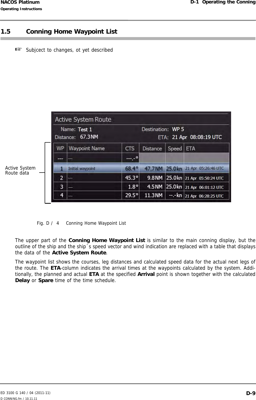
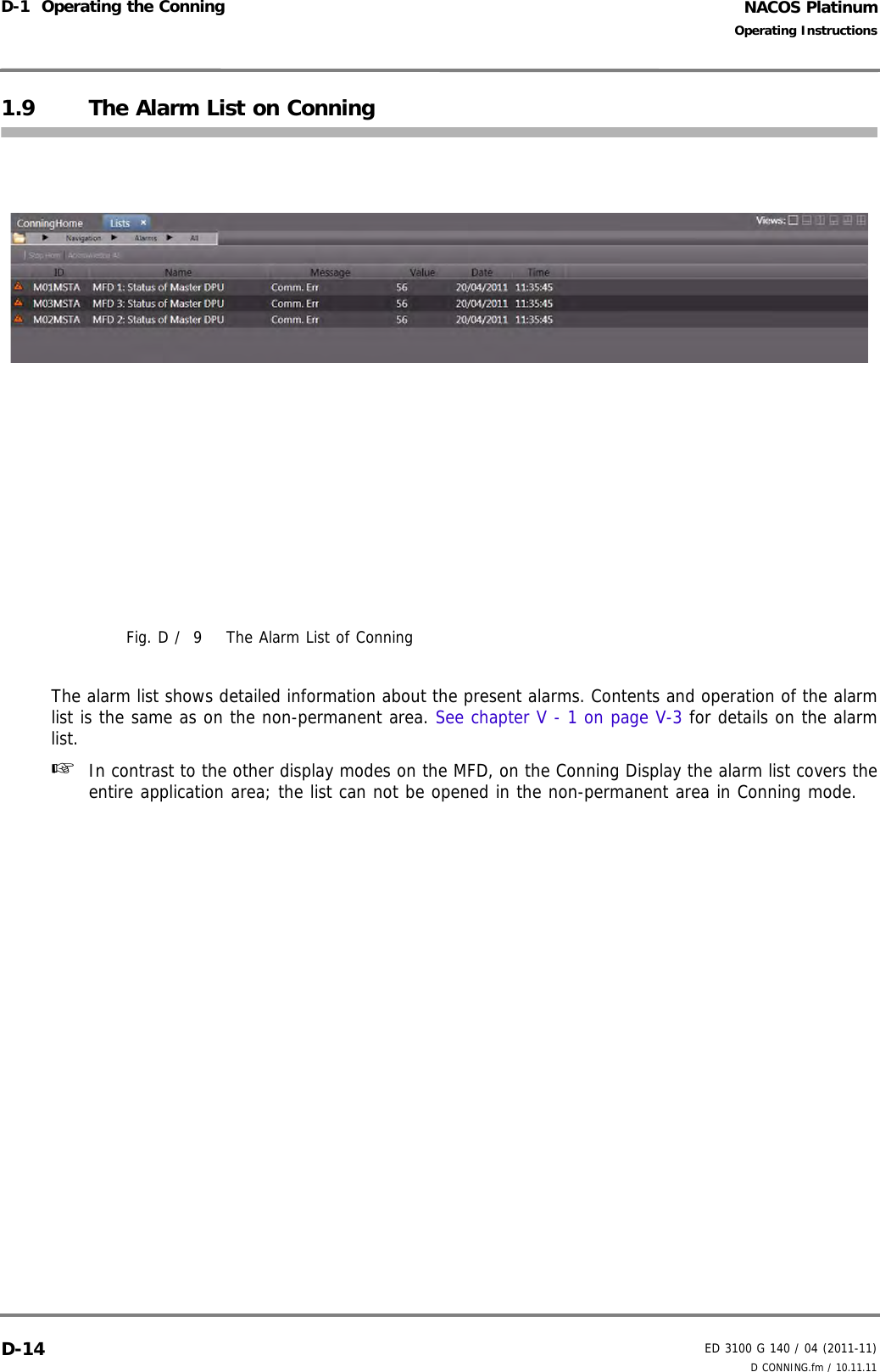
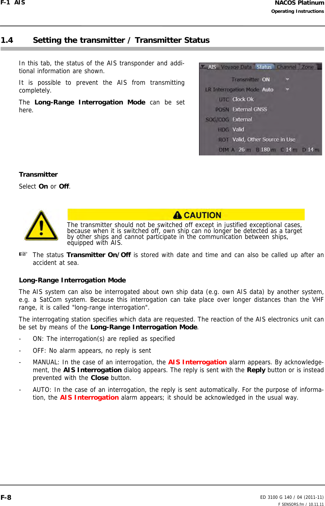
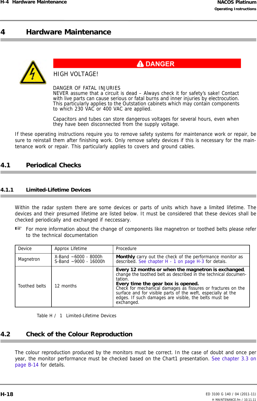
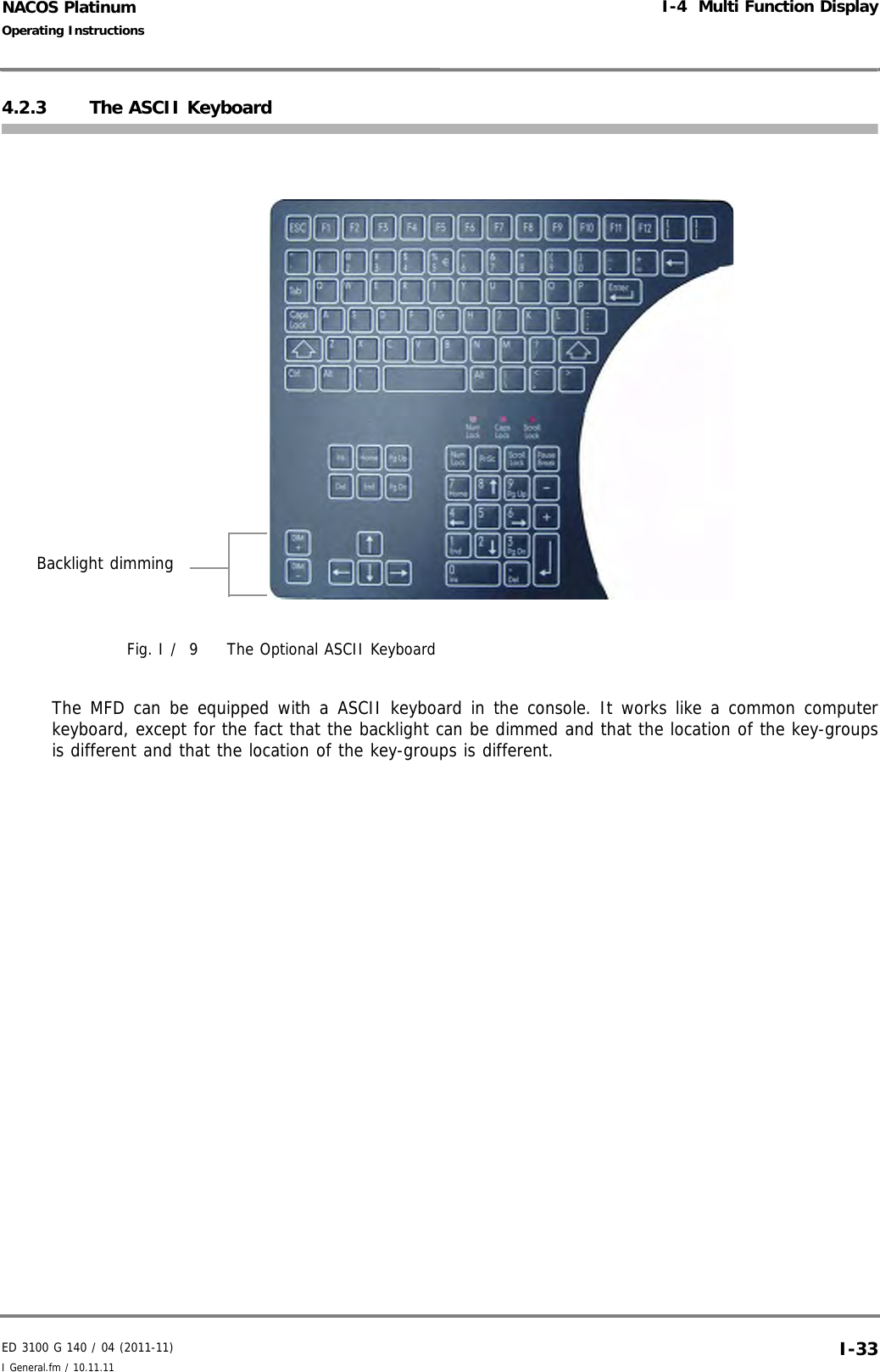
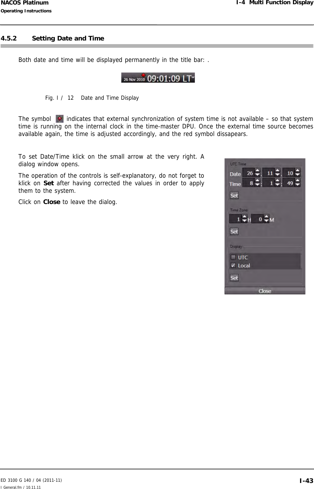
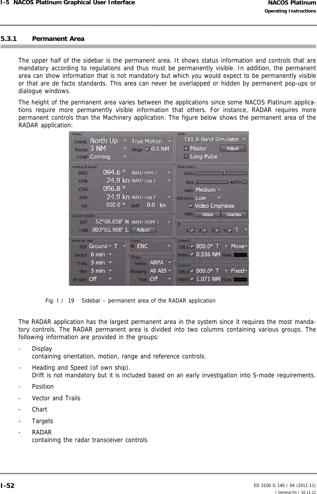
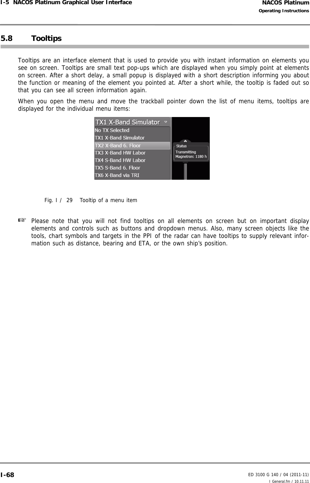
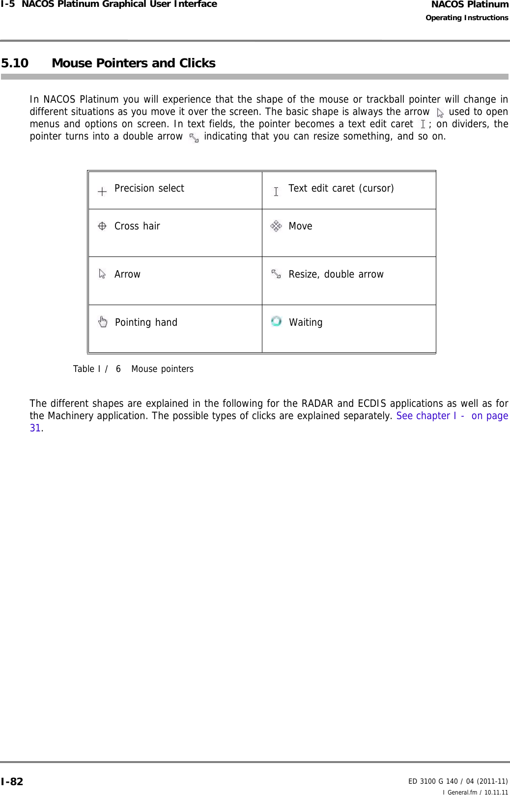
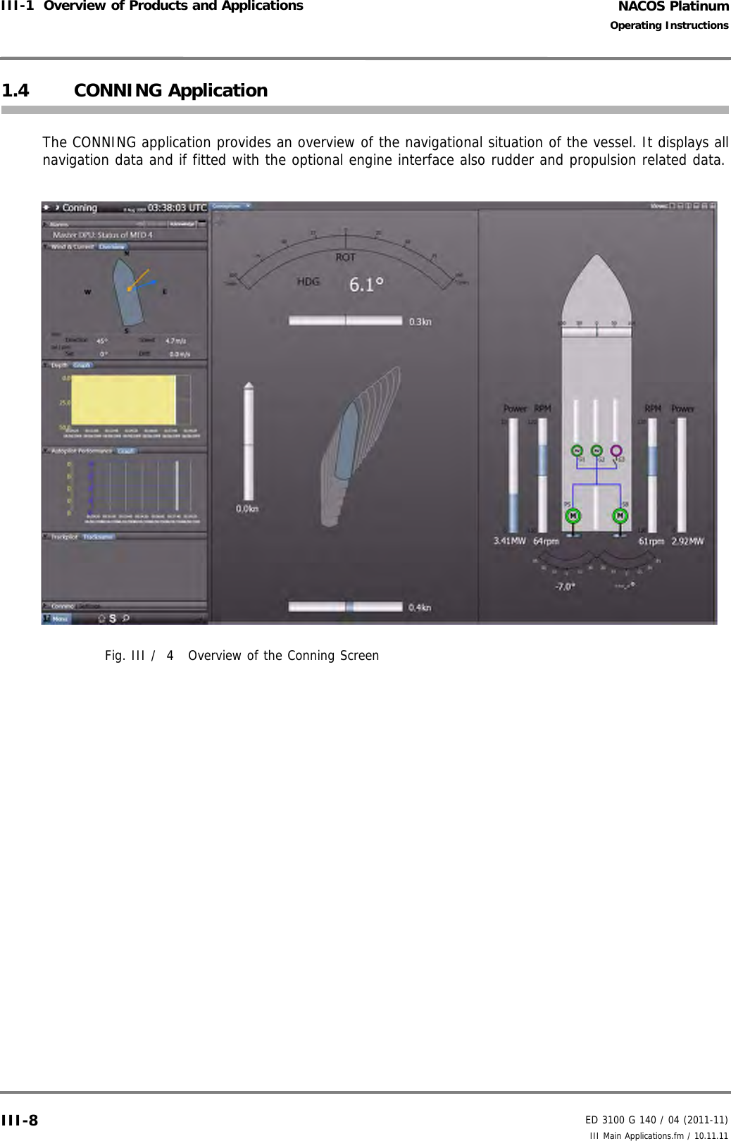
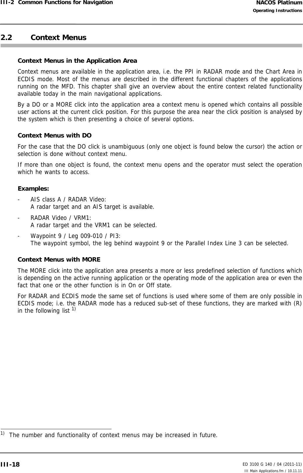
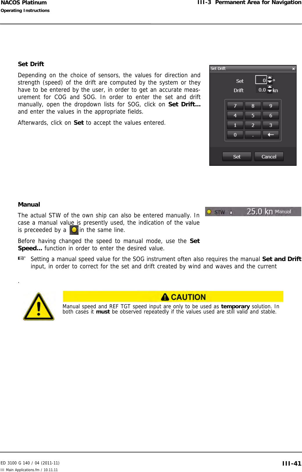
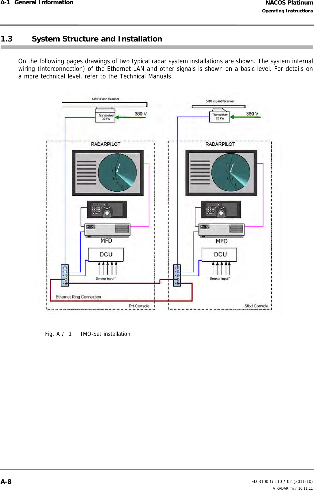
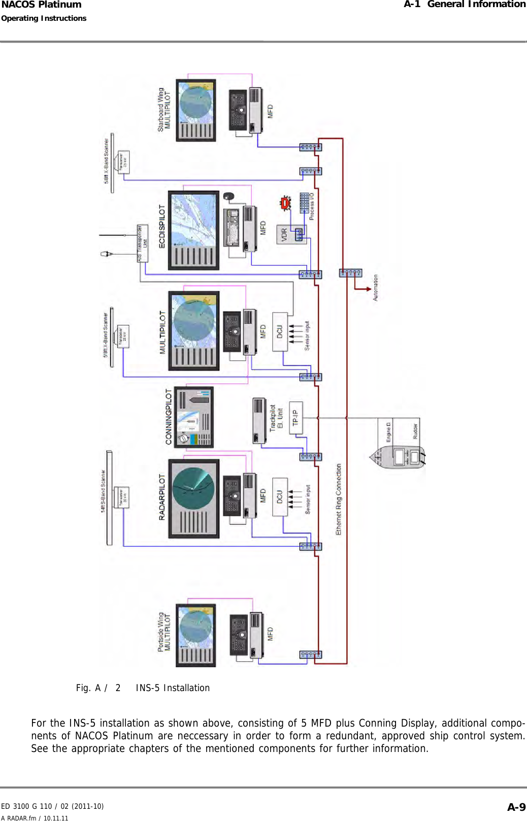
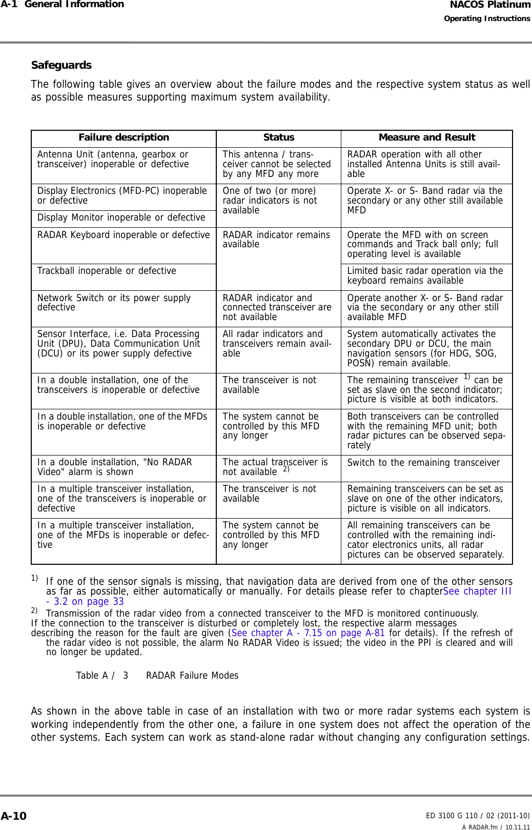
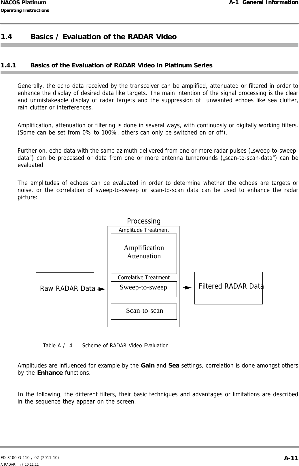
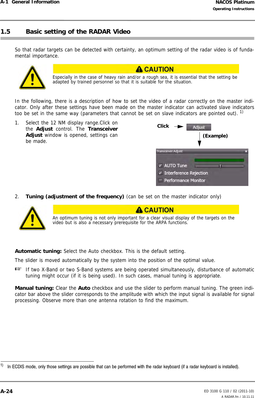
![ED 3100 G 140 / 04 (2011-11)Operating InstructionsI-1 About these Operating InstructionsI General.fm / 10.11.11 I-9NACOS Platinum1.4.2 How to find Information on Specific SubjectsThere will also be the case that you are basically familiar with the NACOS Platinum but only need punc-tual information on one specific topic or detail. In order to find information on such specific subjects, youcan use the- List of Contents- Index of key wordsHere, you can look up specific key words. You will also find, e.g. the names of functions, controls,and keys like [ESC] or [DUTY] at the beginning of the index.- II-QUICK START GUIDE Here you will find essential information on the individual applications which will give you a quickoverview of important functions.- List of AbbreviationsWhen describing a system like the NACOS Platinum, it is necessary to use terms and expressionswhich may be unfamiliar to you in the beginning. Most of the technical terms will be explained toyou as you read your way through the more general chapters, or when reading the chapters on thespecific applications. However, as a general source of information we have provided a list of abbre-viations. See VI-LISTS AND INDEXES.](https://usermanual.wiki/SAM-Electronics/NG3051S30KW/User-Guide-1588887-Page-19.png)
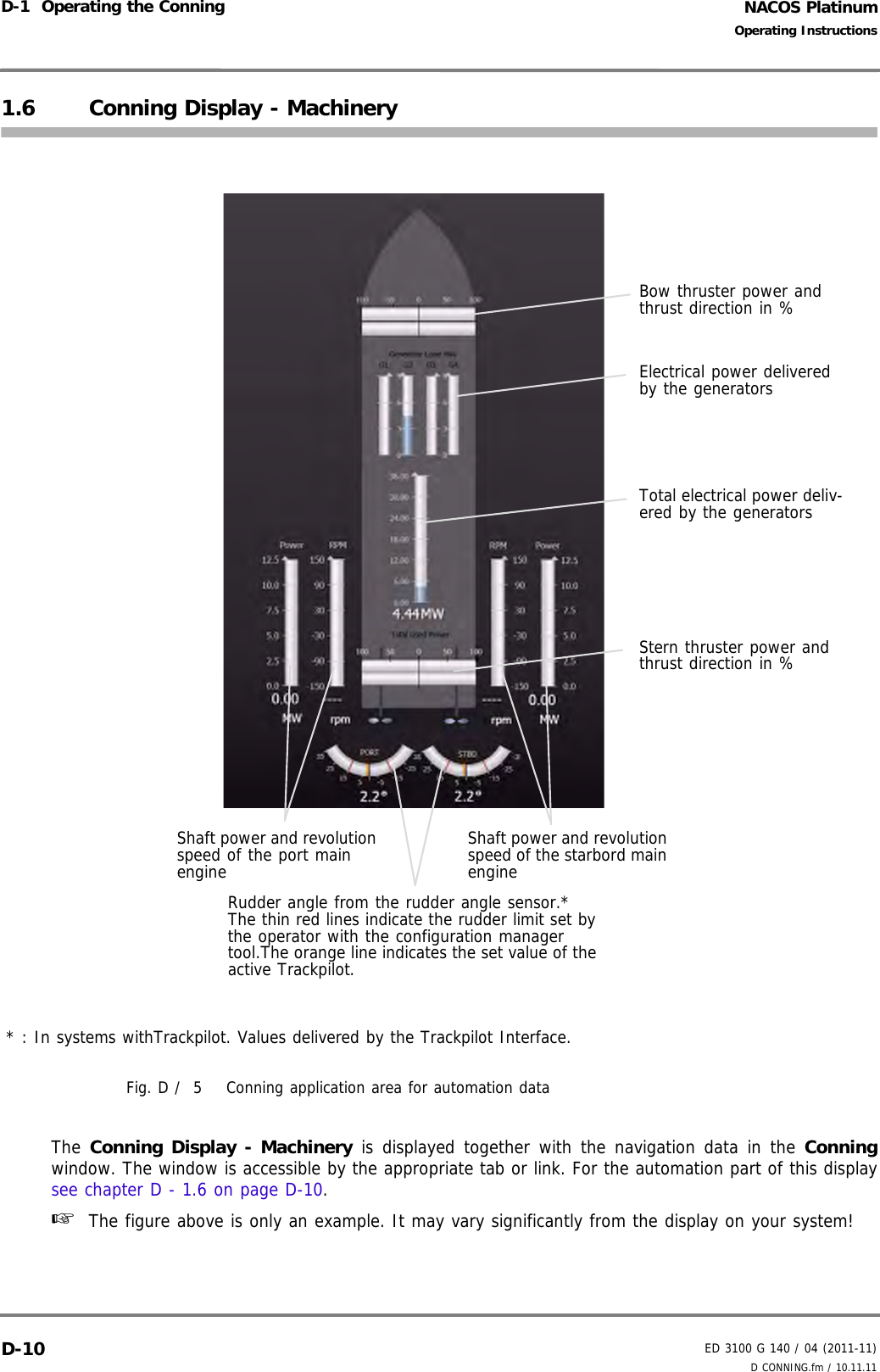
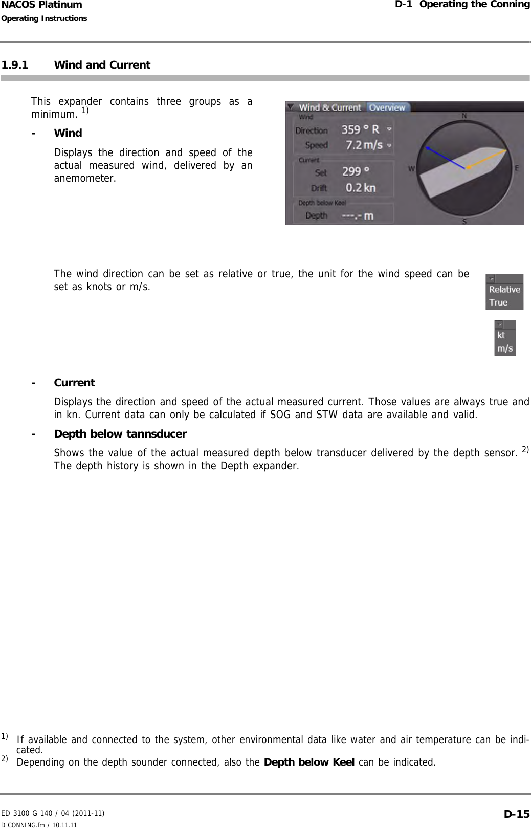
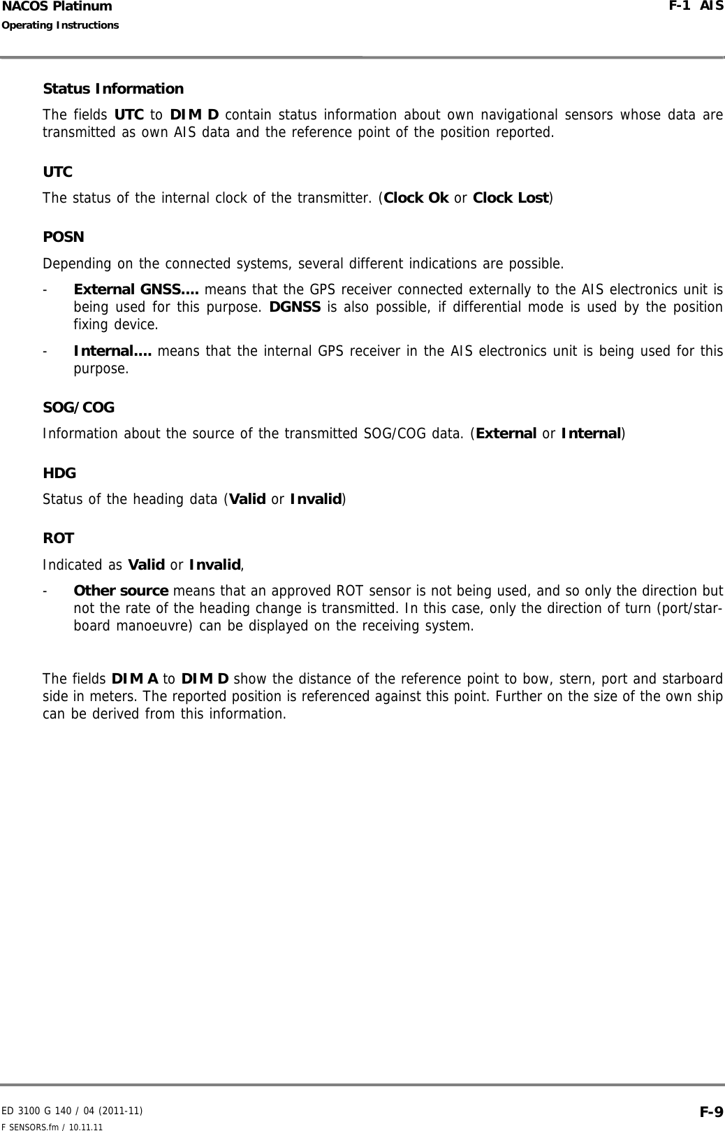
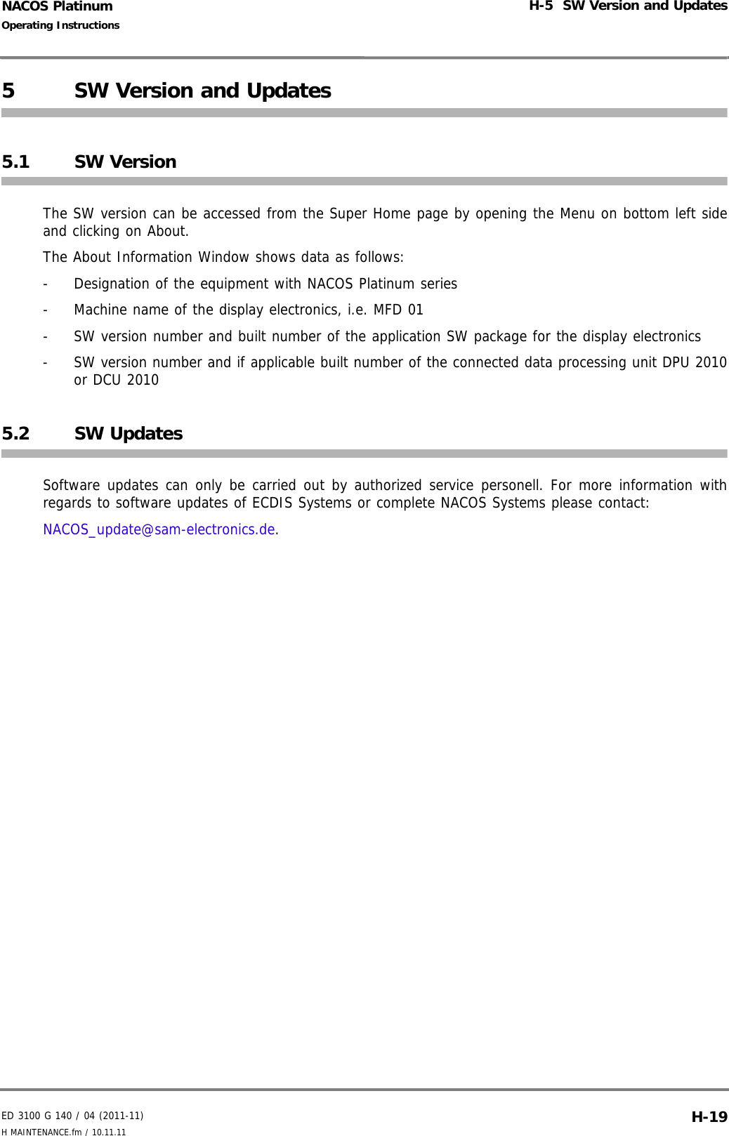
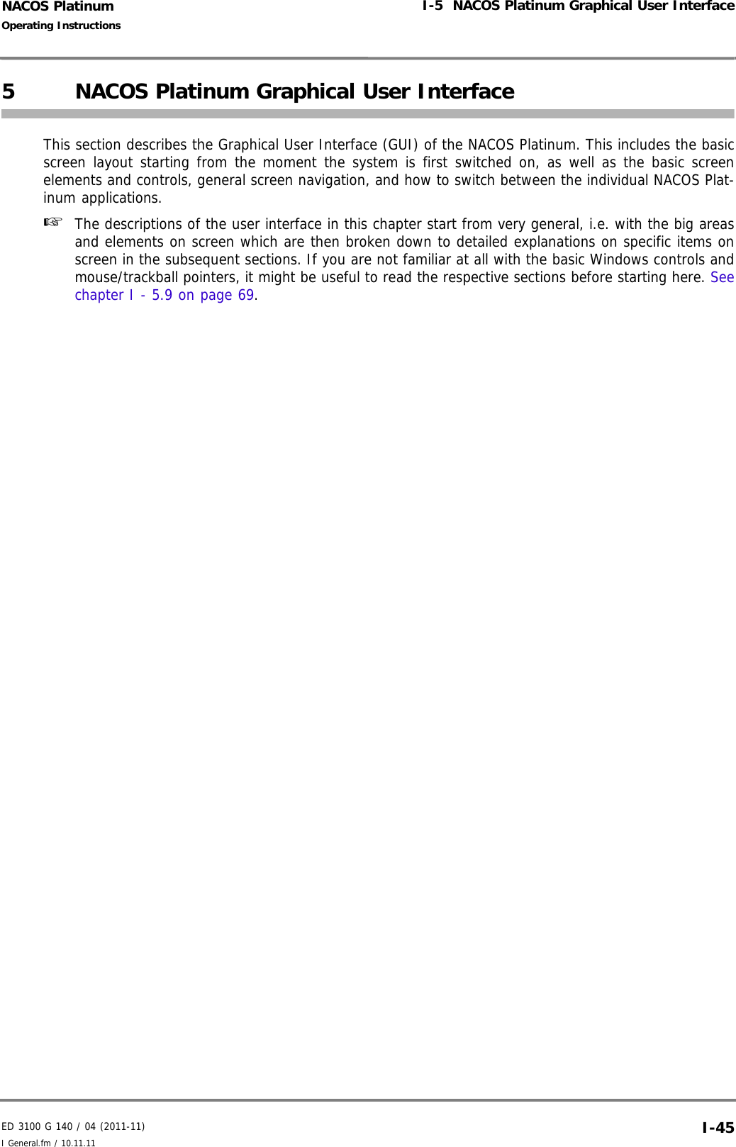
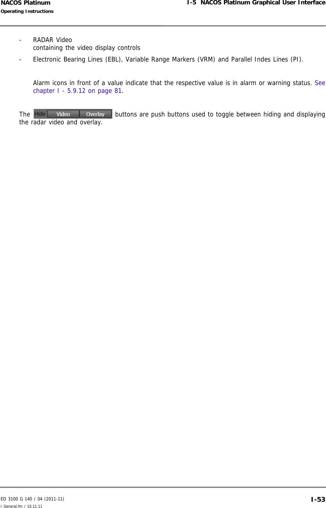
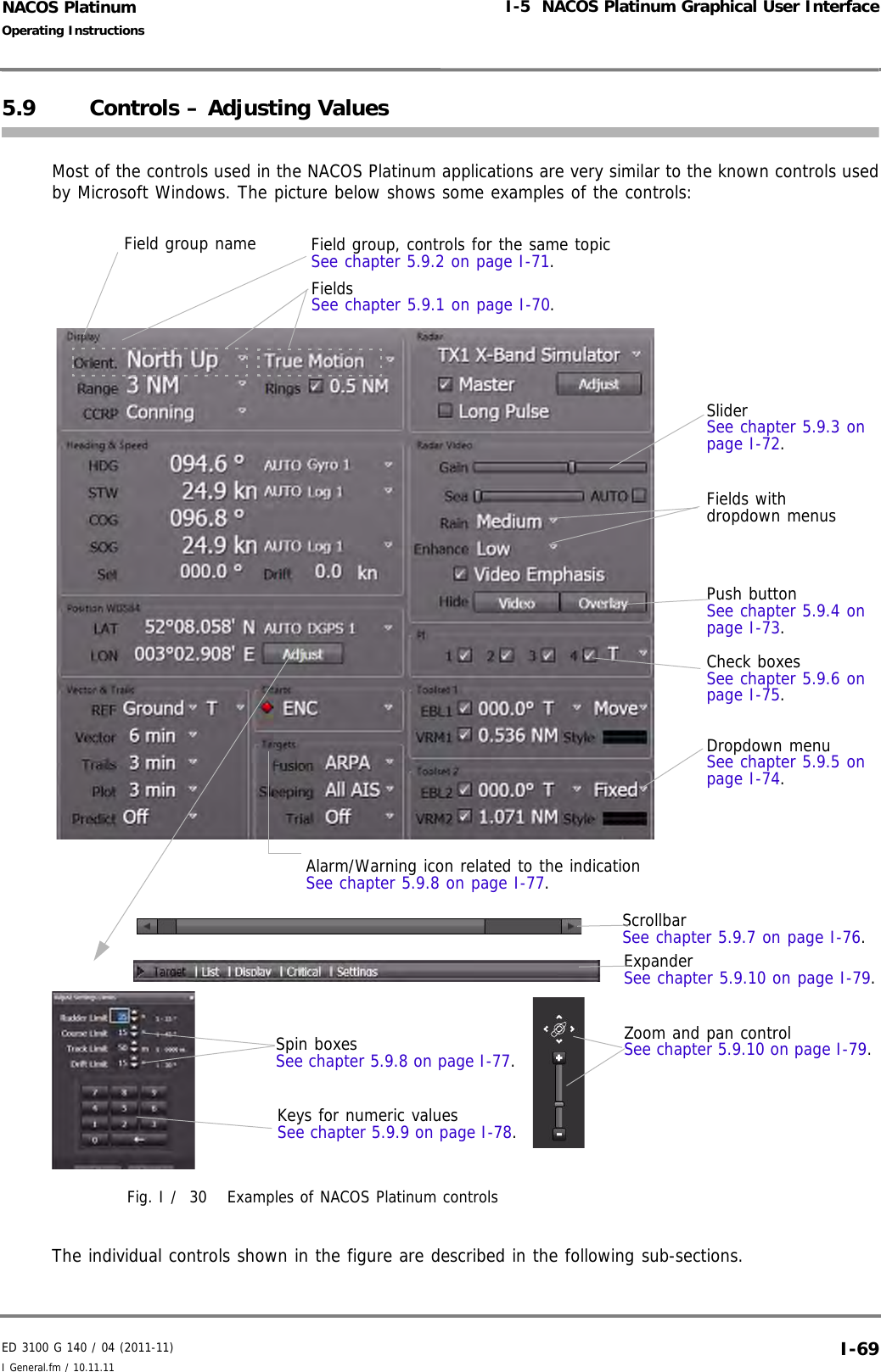
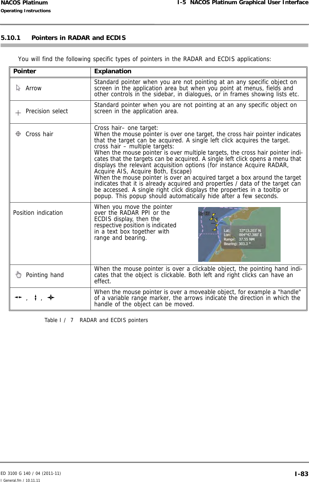
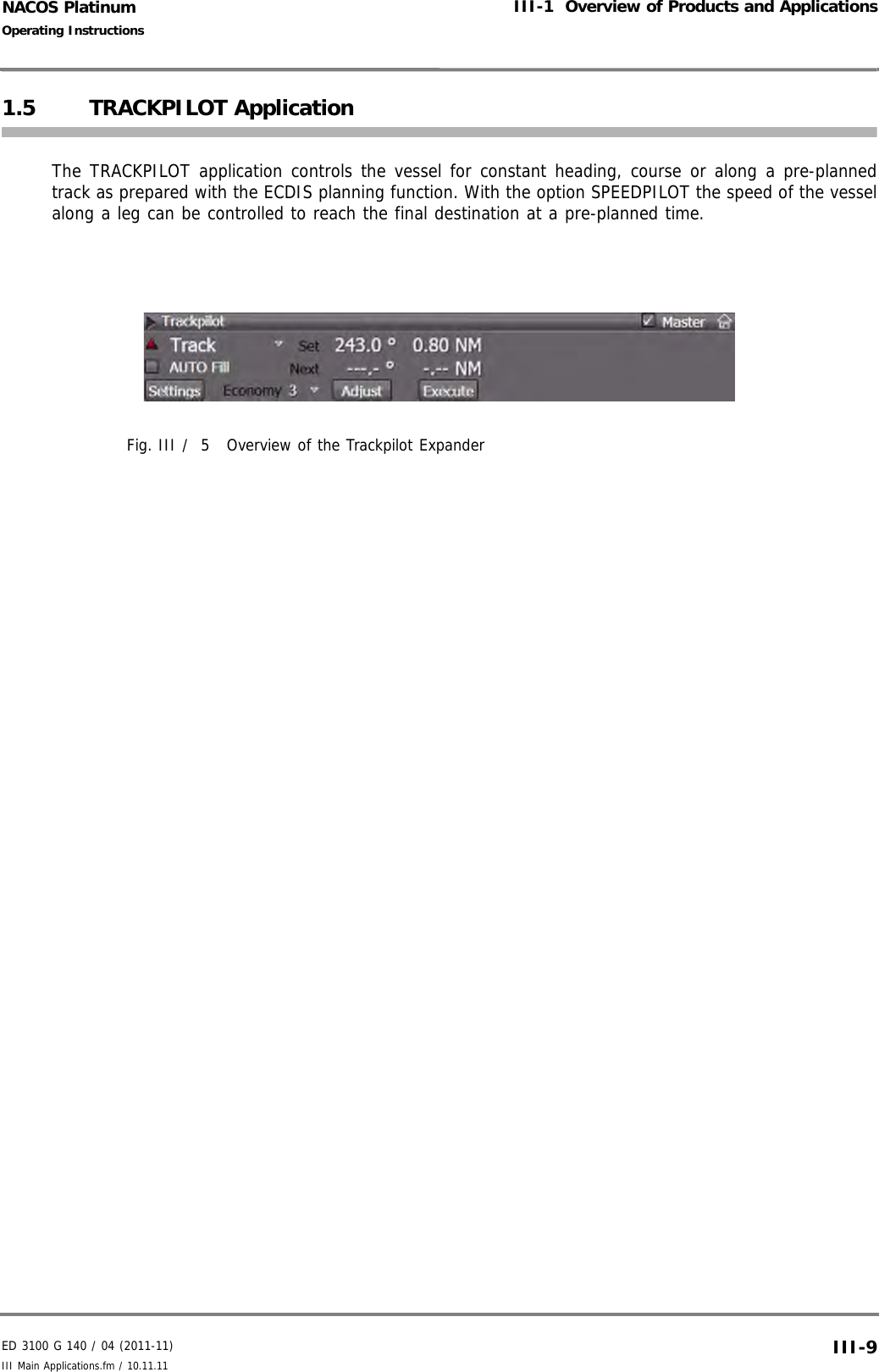
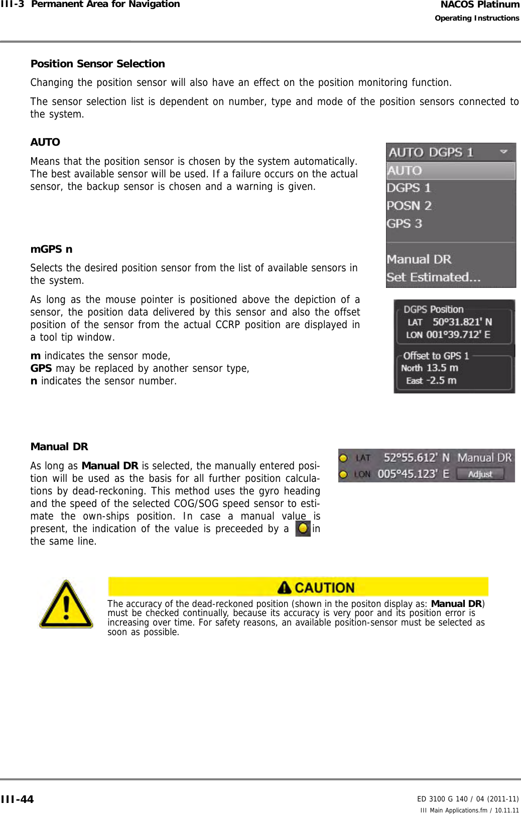
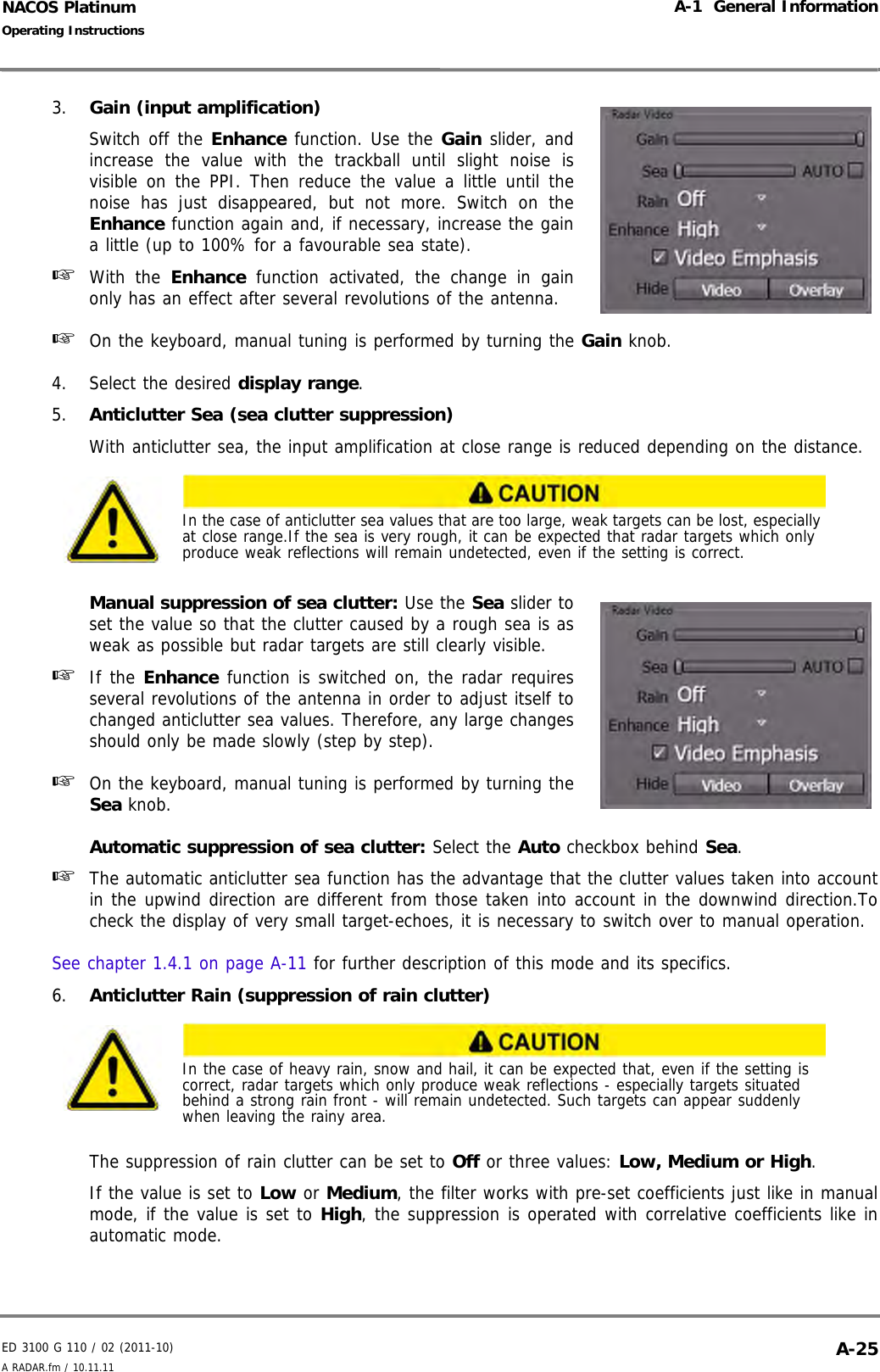
![NACOS PlatinumED 3100 G 140 / 04 (2011-11)Operating InstructionsI-1 About these Operating Instructions I General.fm / 10.11.11I-101.5 Typographical ConventionsThe typographical conventions used in the operating instructions are kept simple, but still it is essentialthat you are sure to understand their meaning before reading the instructions. The following special signsare used for specific purposes:[ ] (square brackets),< > (triangular brackets),{ } (curly brackets),These signs are used as shown in the following examples:](https://usermanual.wiki/SAM-Electronics/NG3051S30KW/User-Guide-1588887-Page-20.png)
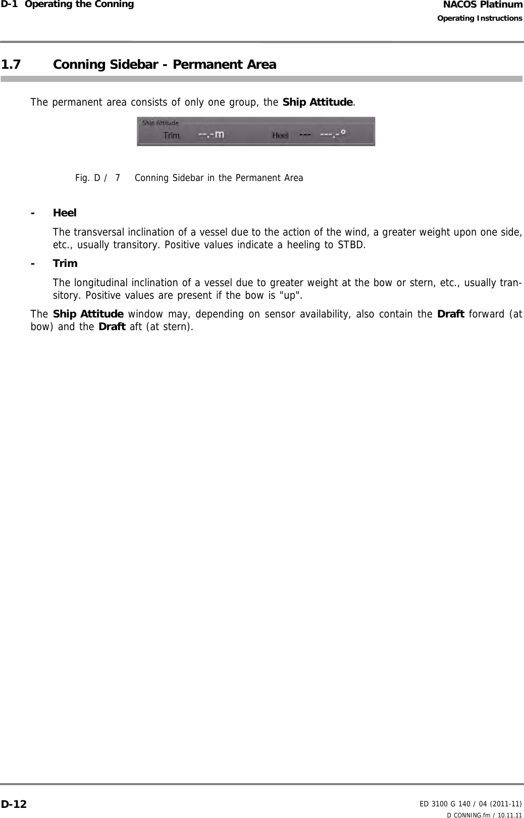
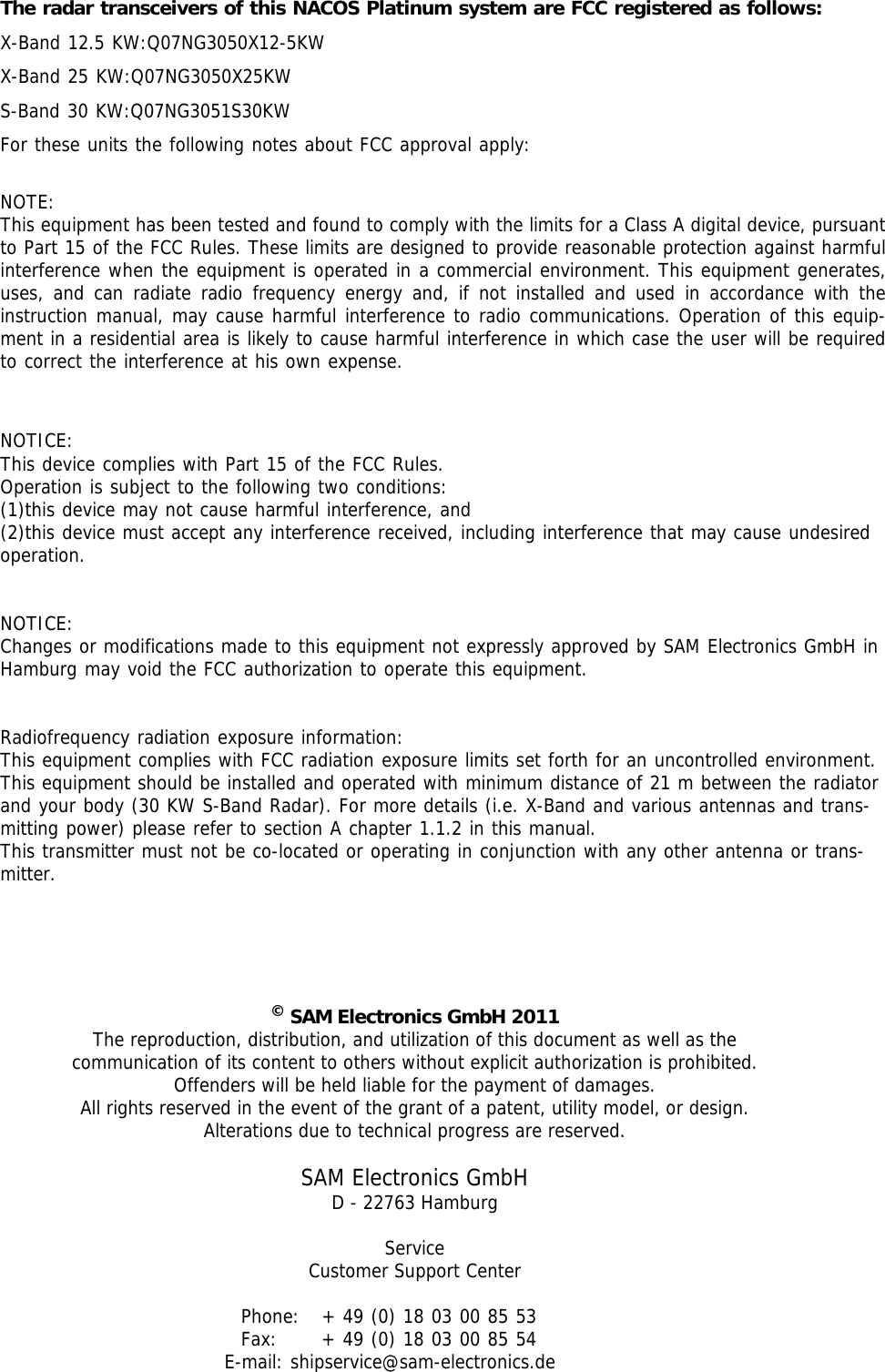
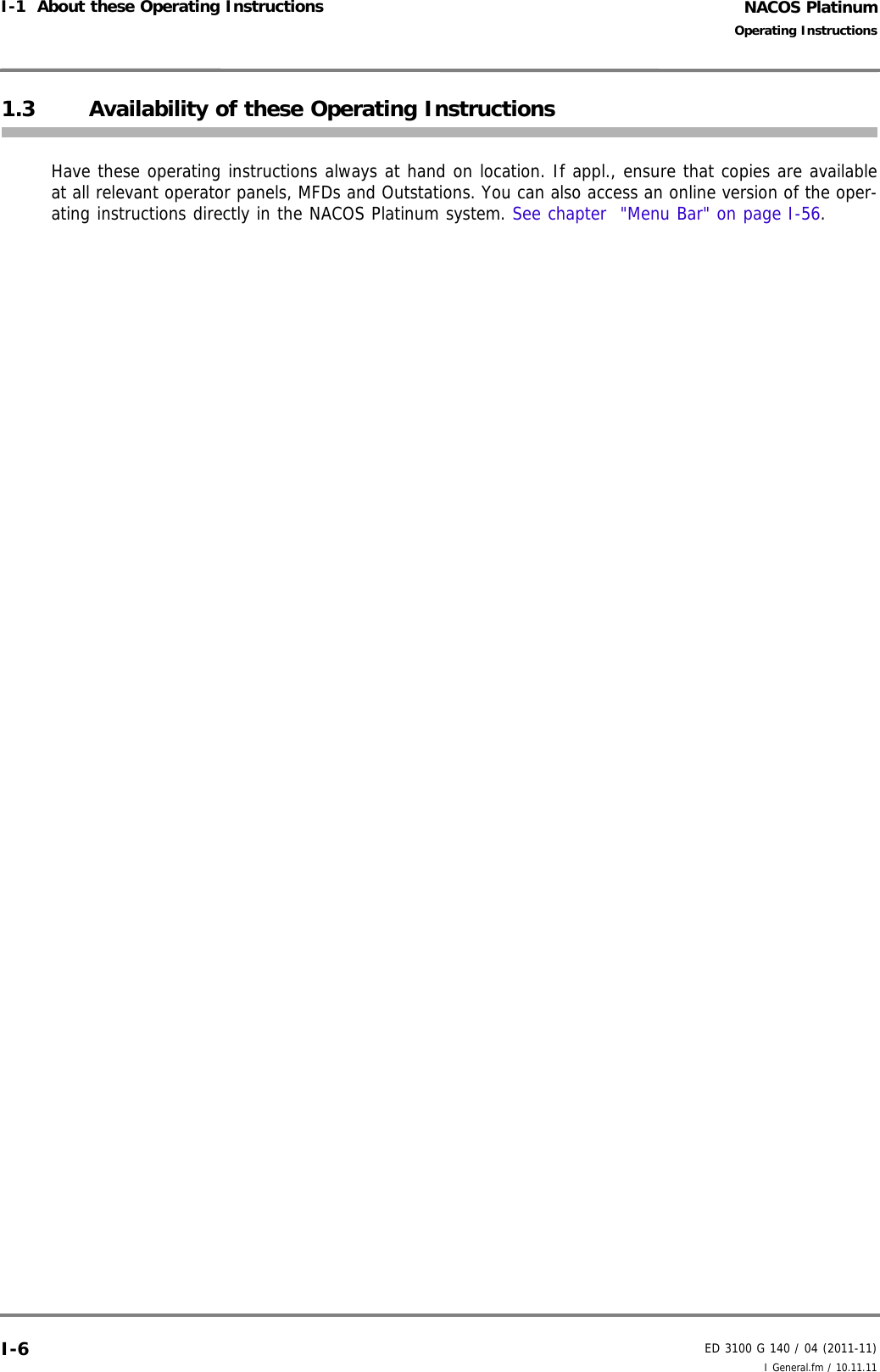
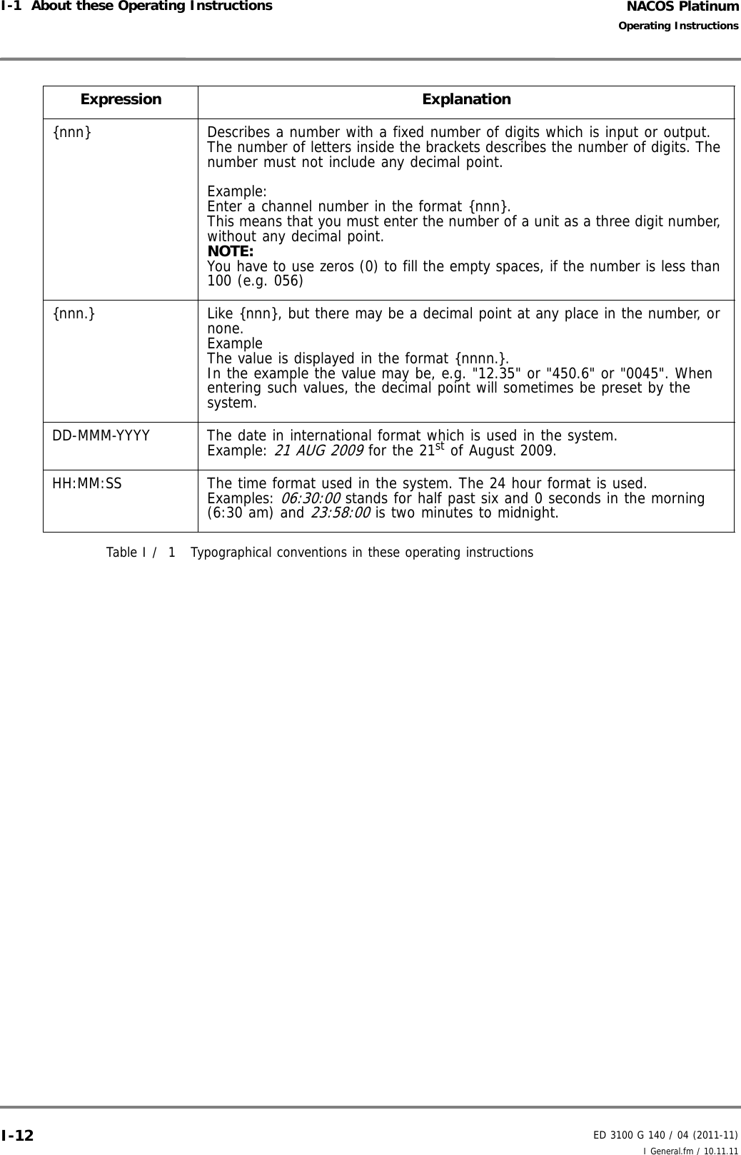
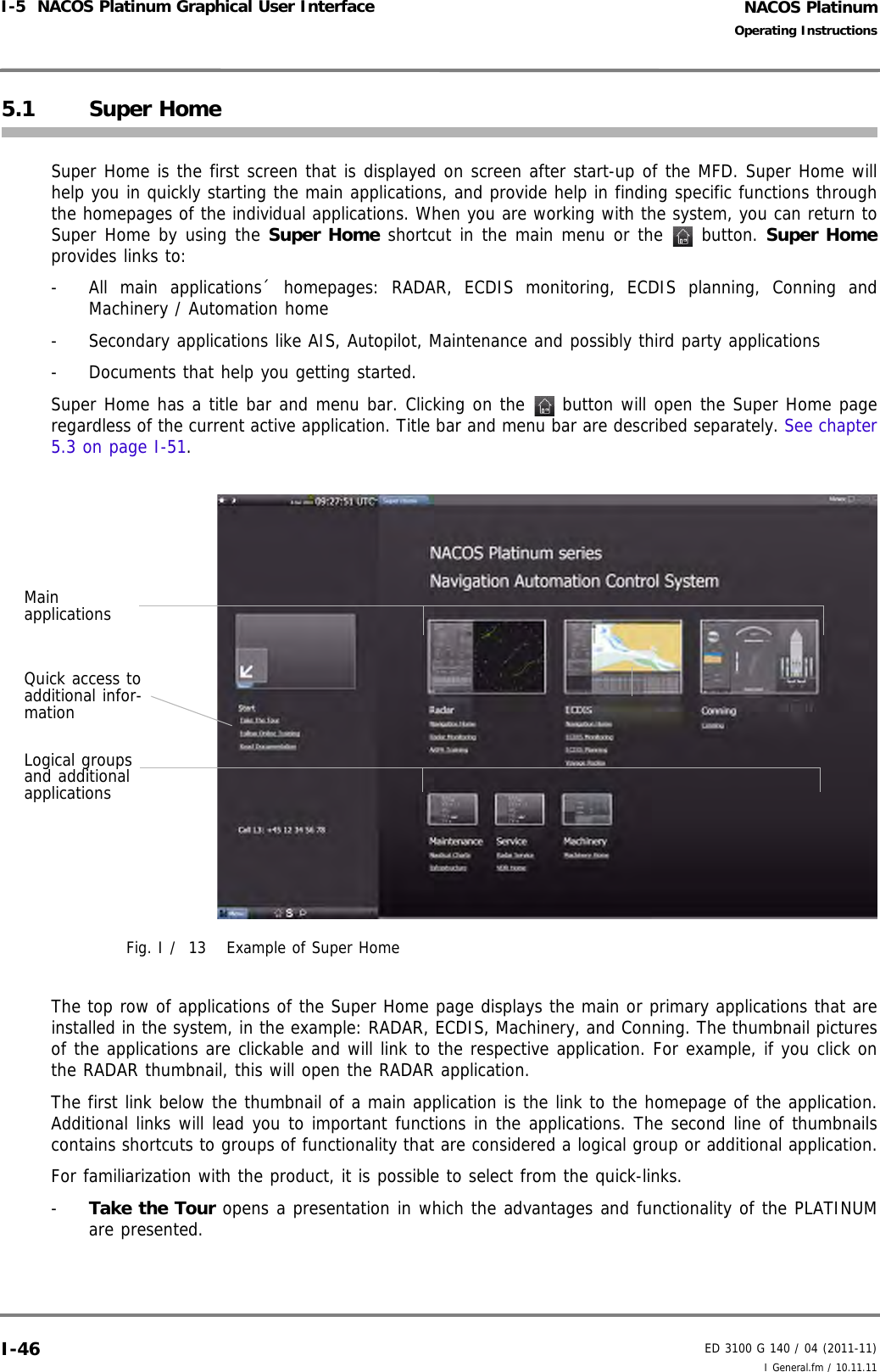
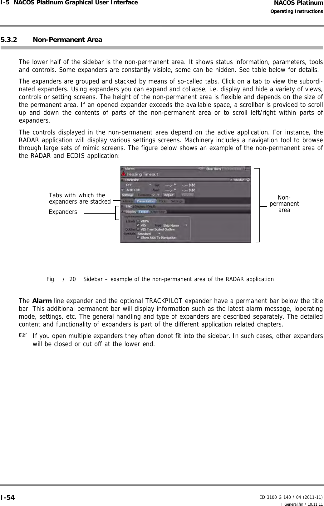
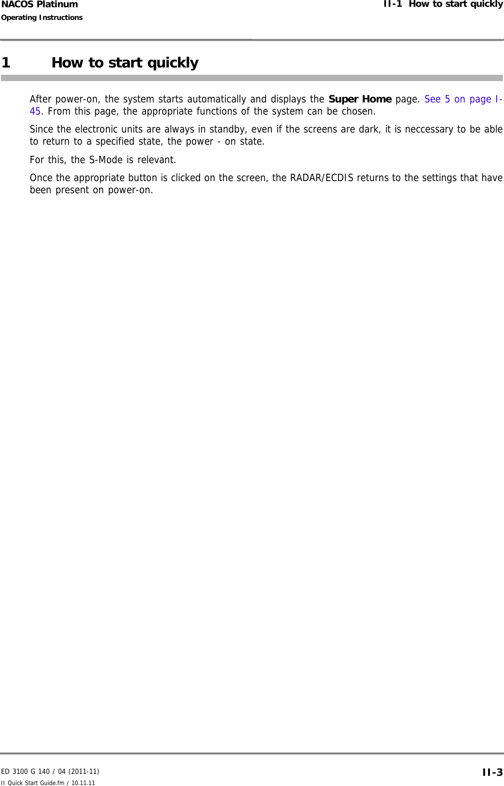
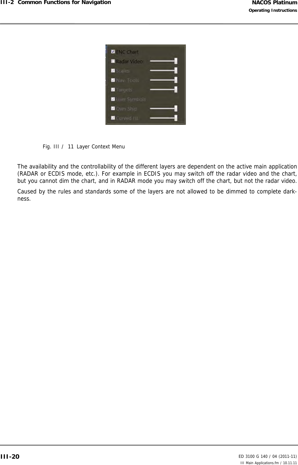
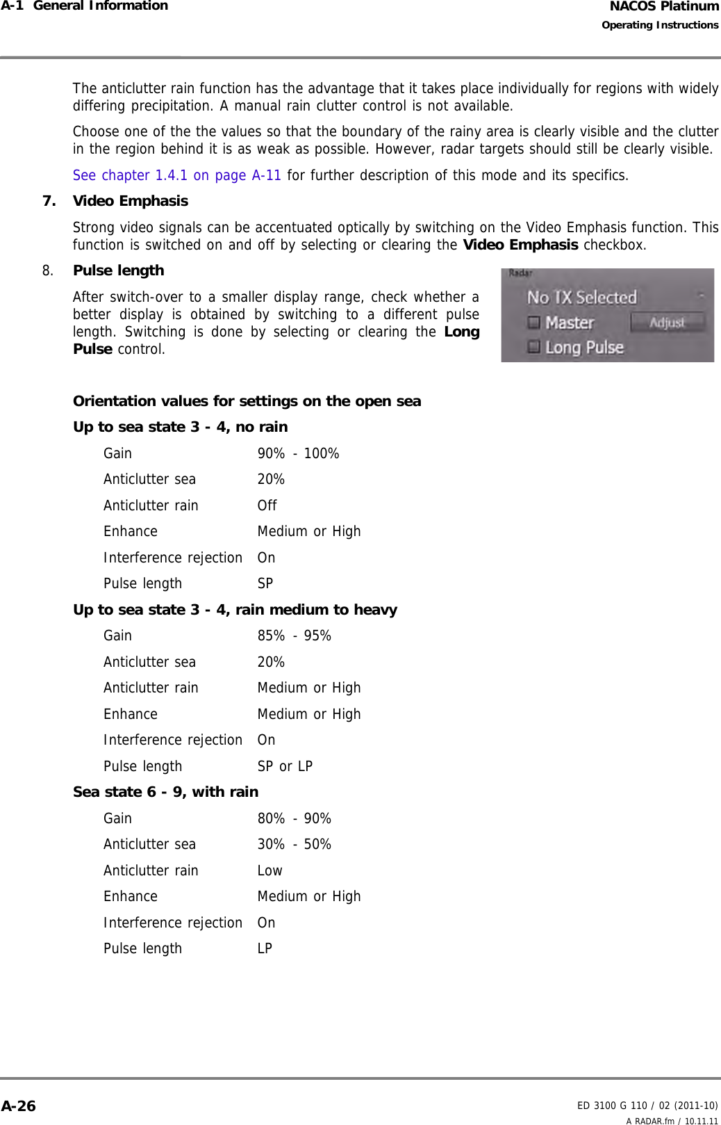
![ED 3100 G 140 / 04 (2011-11)Operating InstructionsI-1 About these Operating InstructionsI General.fm / 10.11.11 I-11NACOS PlatinumExpression Explanation[KEY NAME] This convention is used to refer to an operator key on either a panel keypad (Machinery application), a key on a console’s keyboard, on a computer keyboard, or on the onscreen keyboard.The text is the same text as on the respective key. The text can be letters, digits or signs. Note that the text inside the brackets is written in capital letters.Example:Press [ALARM LIST] to view the Alarm List.This means that you must press the key with the text "ALARM LIST" written on it, in order to view the Alarm List.[KEY] + [2nd KEY] This convention is used to refer to a key combination on the onscreen keyboard or on a computer keyboard. Example:Press [ALT]+[F4] to close the window.This means that you must press and hold the [ALT] key, and while holding the [ALT] key you have to press [F4]. [ ] [ ] [ ] [ ] The symbols in the square brackets refer to the respective arrow keys on operator panels (Machinery application).[ ] [ ] [ ] [ ] The symbols in the square brackets refer to the respective arrow keys on a console’s keyboard, on a computer keyboard, or on the onscreen keyboard.Abcd List Heading capitalisation and bold typeface are used when directly referring to names of NACOS Platinum functions and UI elements such as menus, opera-tional modes, reports, lists, etc. The text can be in more than one word.Examples: Select Color & in the main menu.From any mode you can call up the Alarm List by pressing the [ALARM LIST] key on the panel.Main > Submenu > Sub-Submenu This is an abbreviated way for:Click on Main, then on Submenu and afterwards on Sub-Submenu☞ This symbol indicates a hint.<variable> Describes a text string of variable length and contents.The text inside the brackets is not the actual text, but a reference to a text which is individual to your specific system.The length of the text is not specified by the text inside the brackets.The expression can refer to both text and numbers. Example:The display will show <duty engineer>.This means that the display will show the name of the selected duty engineer, e.g. "3RD ENGINEER".](https://usermanual.wiki/SAM-Electronics/NG3051S30KW/User-Guide-1588887-Page-21.png)
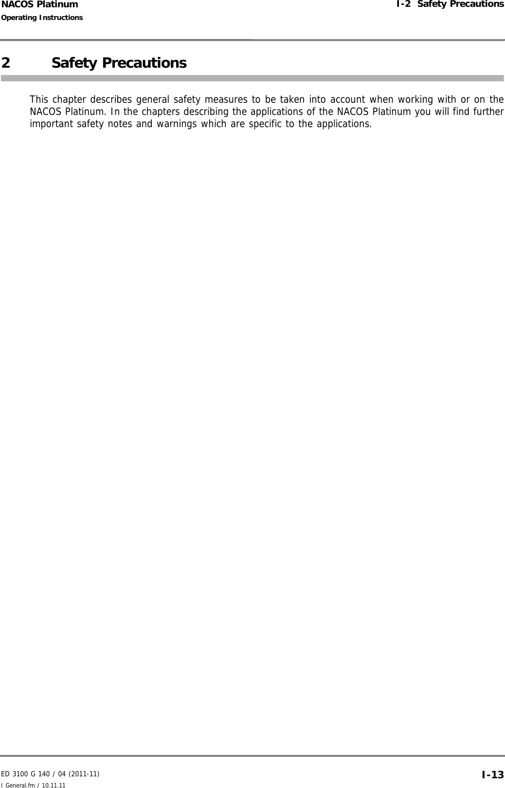


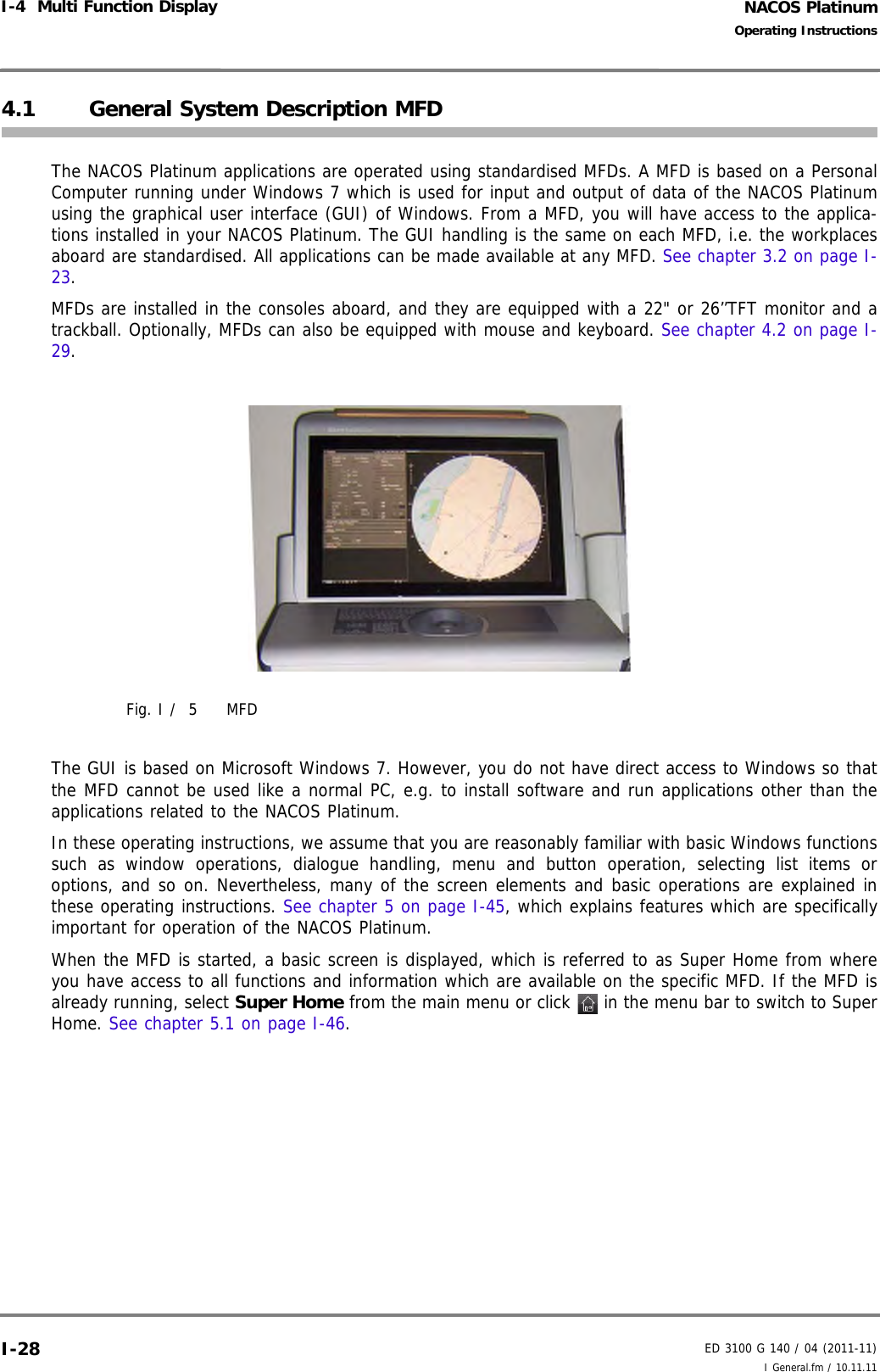

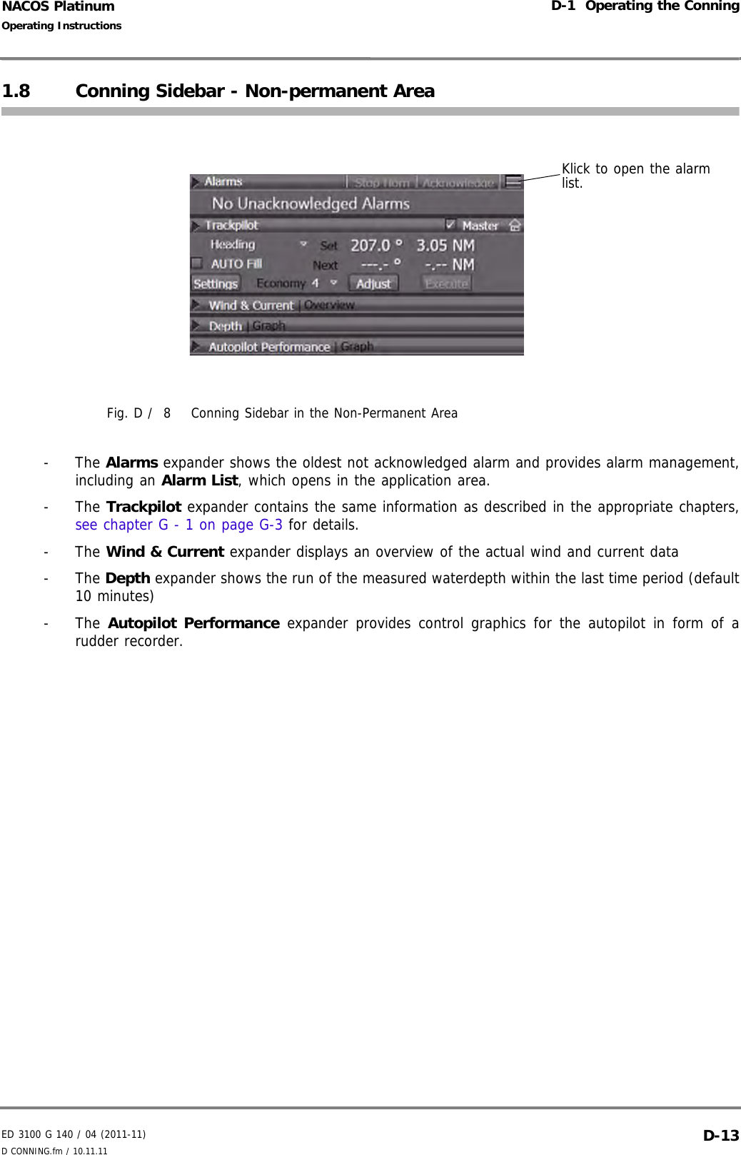
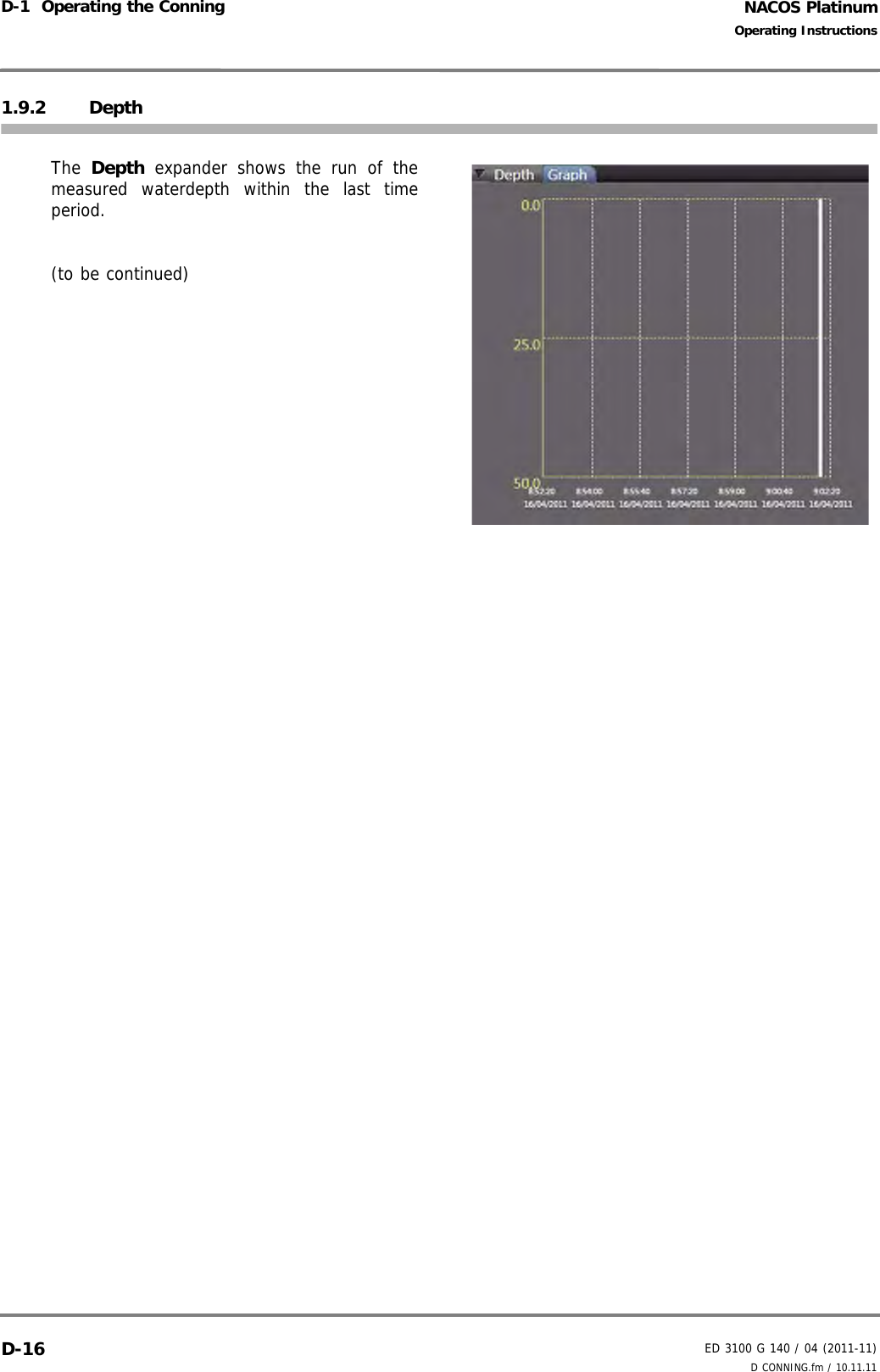
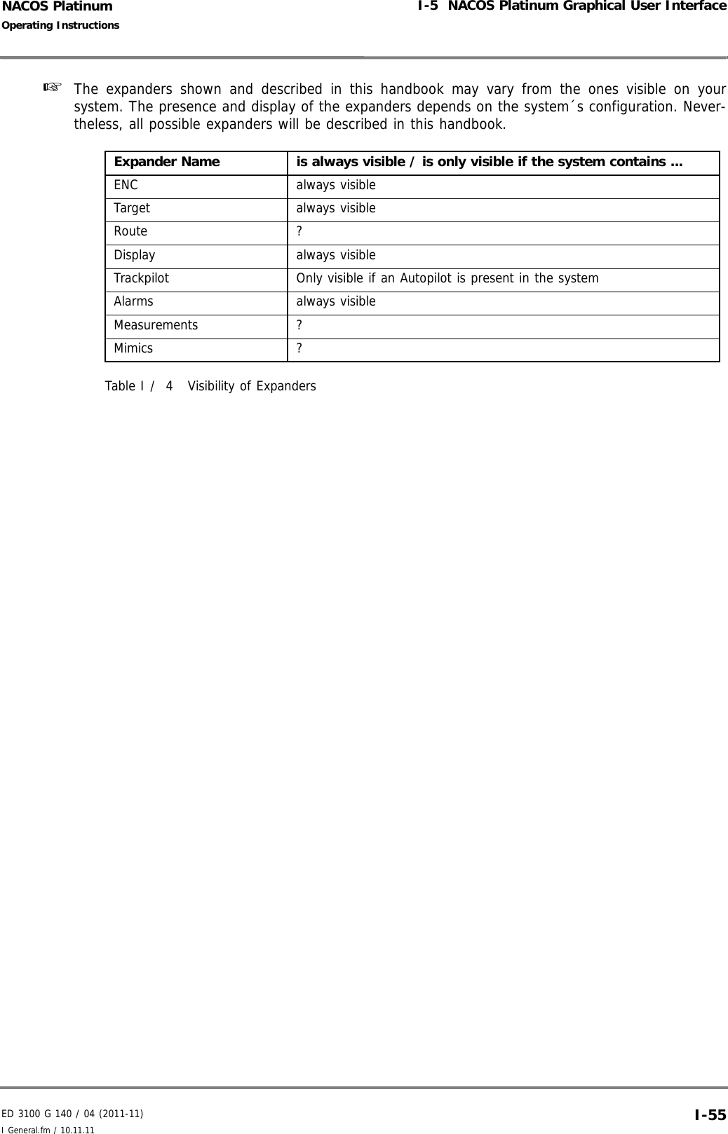
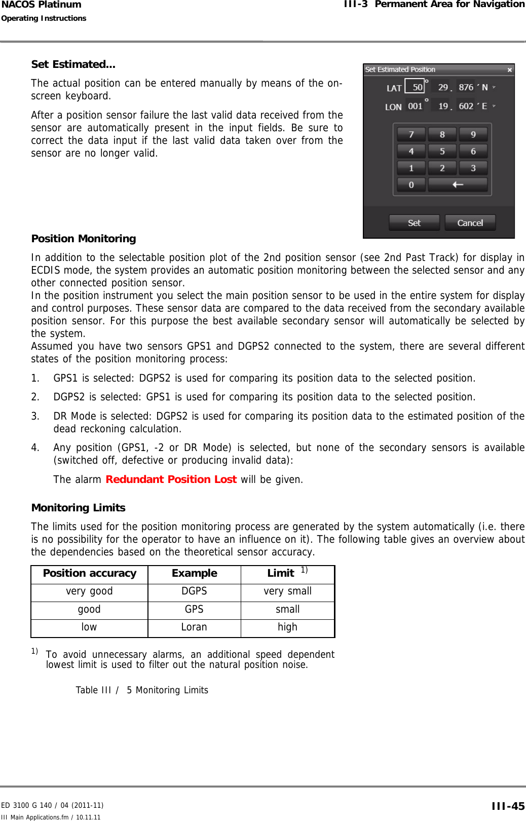
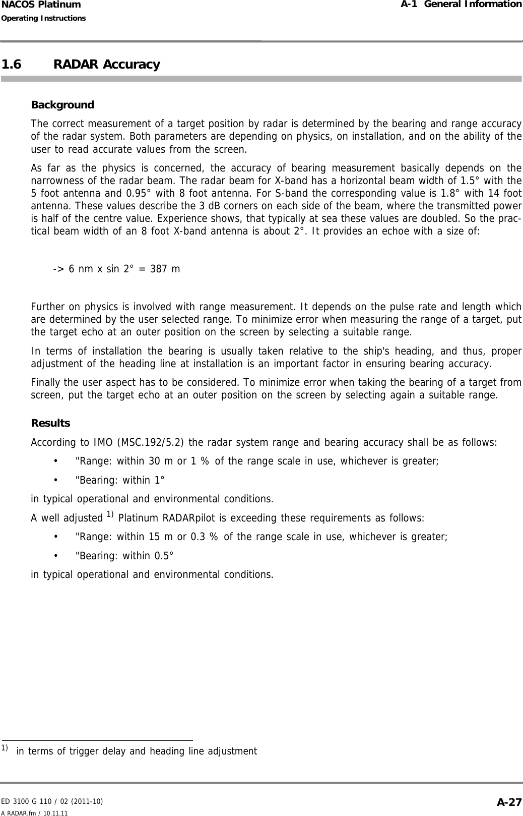
![NACOS PlatinumED 3100 G 140 / 04 (2011-11)Operating InstructionsI-4 Multi Function Display I General.fm / 10.11.11I-404.4 Startup and Shutdown of MFDs☞ The NACOS Platinum and the related consoles and the electronics equipment are permanently upand running. They are only completely shut down by qualified authorised service personnel in caseof servicing and repair. The system components are then separated from the mains using a mainswitch on the bridge. When switching on the mains supply again, the equipment will startup auto-matically without further user action.This section describes how to use the shut-down function, if this is required, e.g. if the power supply hasto be switched off during a dockyard period, or if an individual MFD shall be switched off for specificreasons. Proceed as follows to switch off a MFD:1. Press [Alt] + [F4], or click the Menu button and then Shut Down. 2. Enter the required password.3. In the window which is displayed, select Shut Down and click OK.The other options Reboot or Log off can be used to re-boot the MFD immediately or to log offand on again. 4. Separate the unit from the mains using the mains switch on the bridge.This way, the NACOS Platinum program is terminated and the PC is shut down. The display will beswitched off automatically. To switch on the MFD use the main power switch (if appl., refer to the drawings in the delivery docu-ments). It will automatically start up and run in normal operating state, Super Home is displayed. If theMFD is already up and running and displaying a screensaver, just move the trackball slightly to displaythe graphical user interface of the MFD. As long as the ship is at sea and in operation, the NACOS Platinum must be fully operational, i.e. the NACOS Platinum and its applications must not be shut down. UPS systems must not be deactivated. Never switch off a MFD without having completed the described shutdown proce-dure. The TFT display will probably function in a normal manner when just switching off the power and then switching it on again. However, and this applies to all types of PCs used: if, at the moment it is switched off, the PC accesses the hard disk, the hard disk might be permanently damaged resulting in system failure of the MFD and loss of data.](https://usermanual.wiki/SAM-Electronics/NG3051S30KW/User-Guide-1588887-Page-50.png)


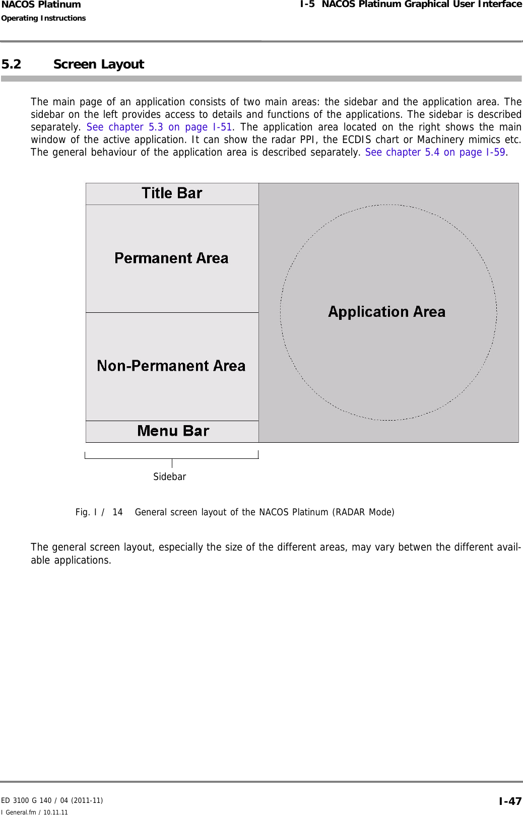

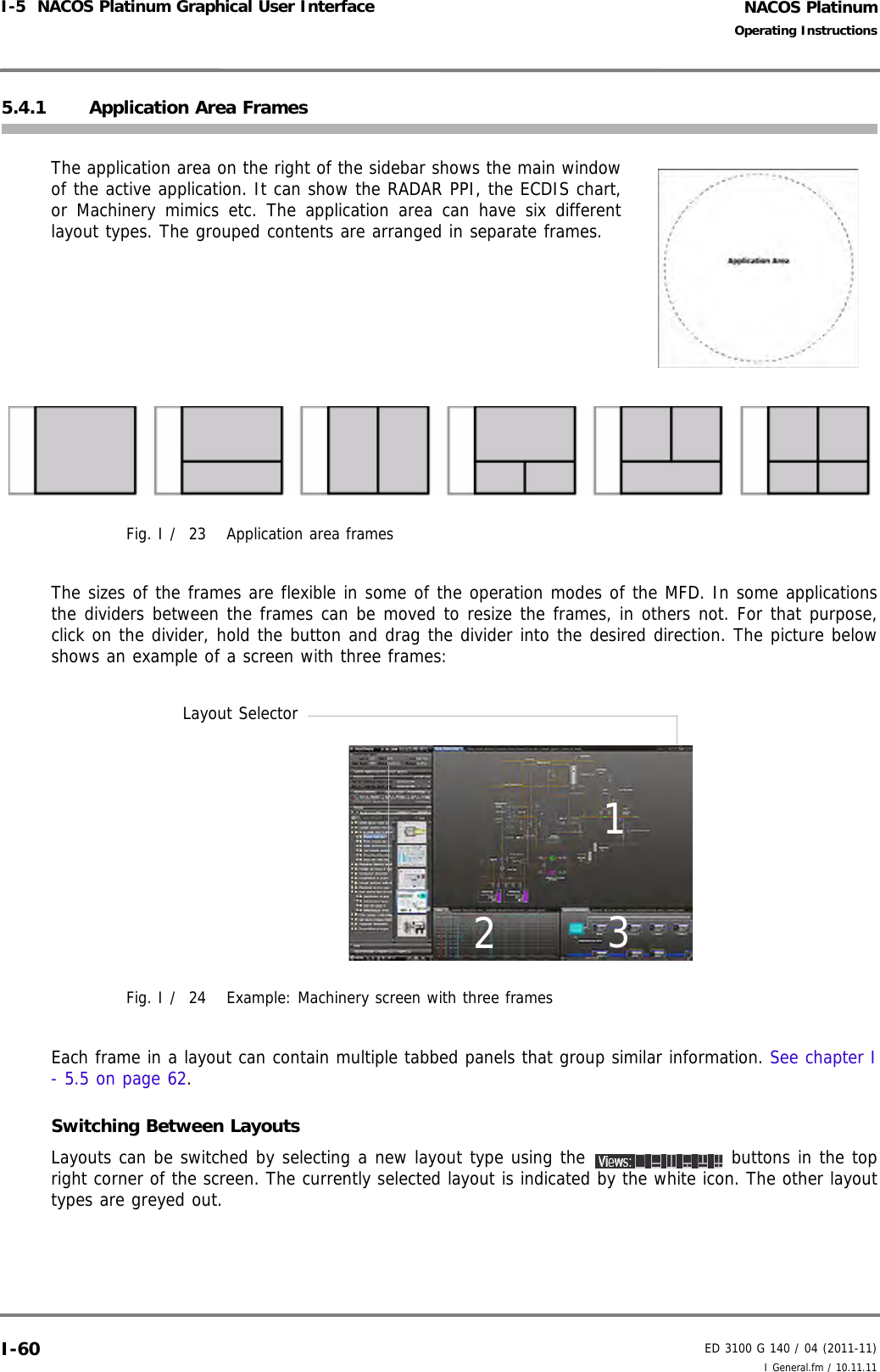
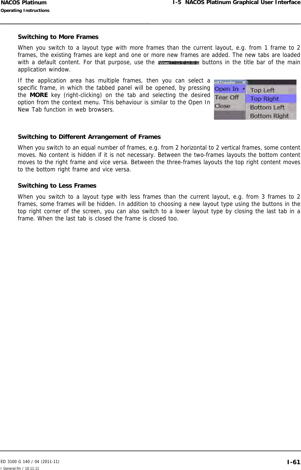
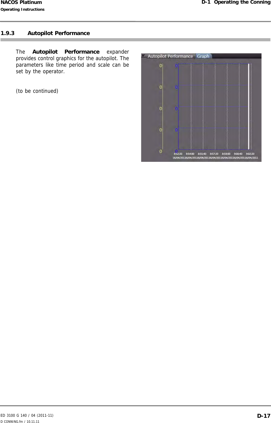
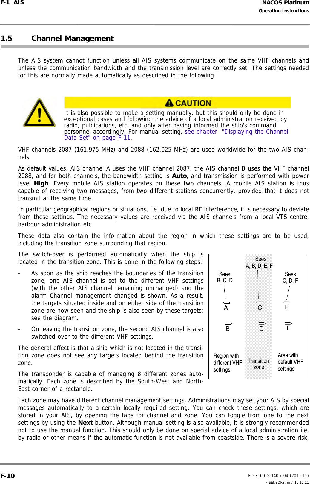
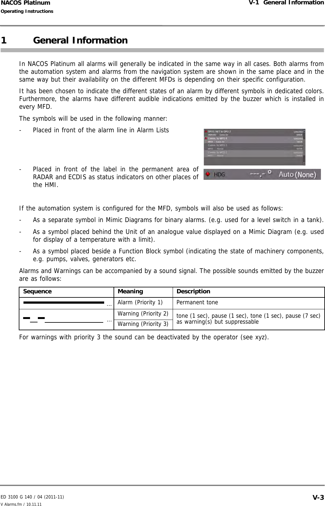
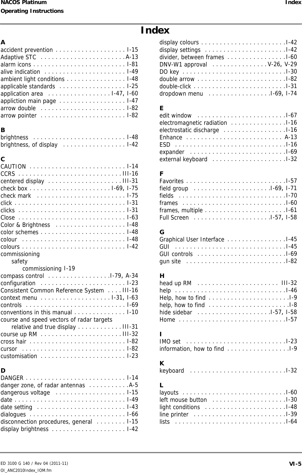
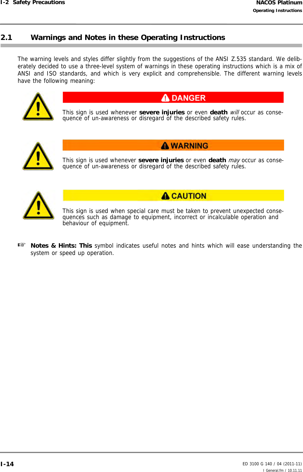
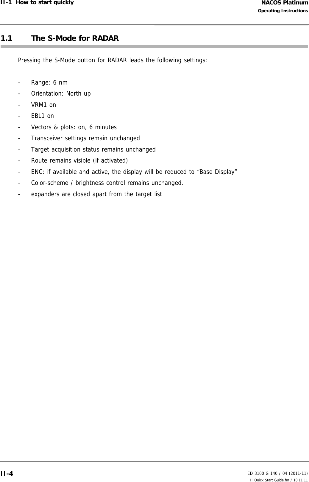
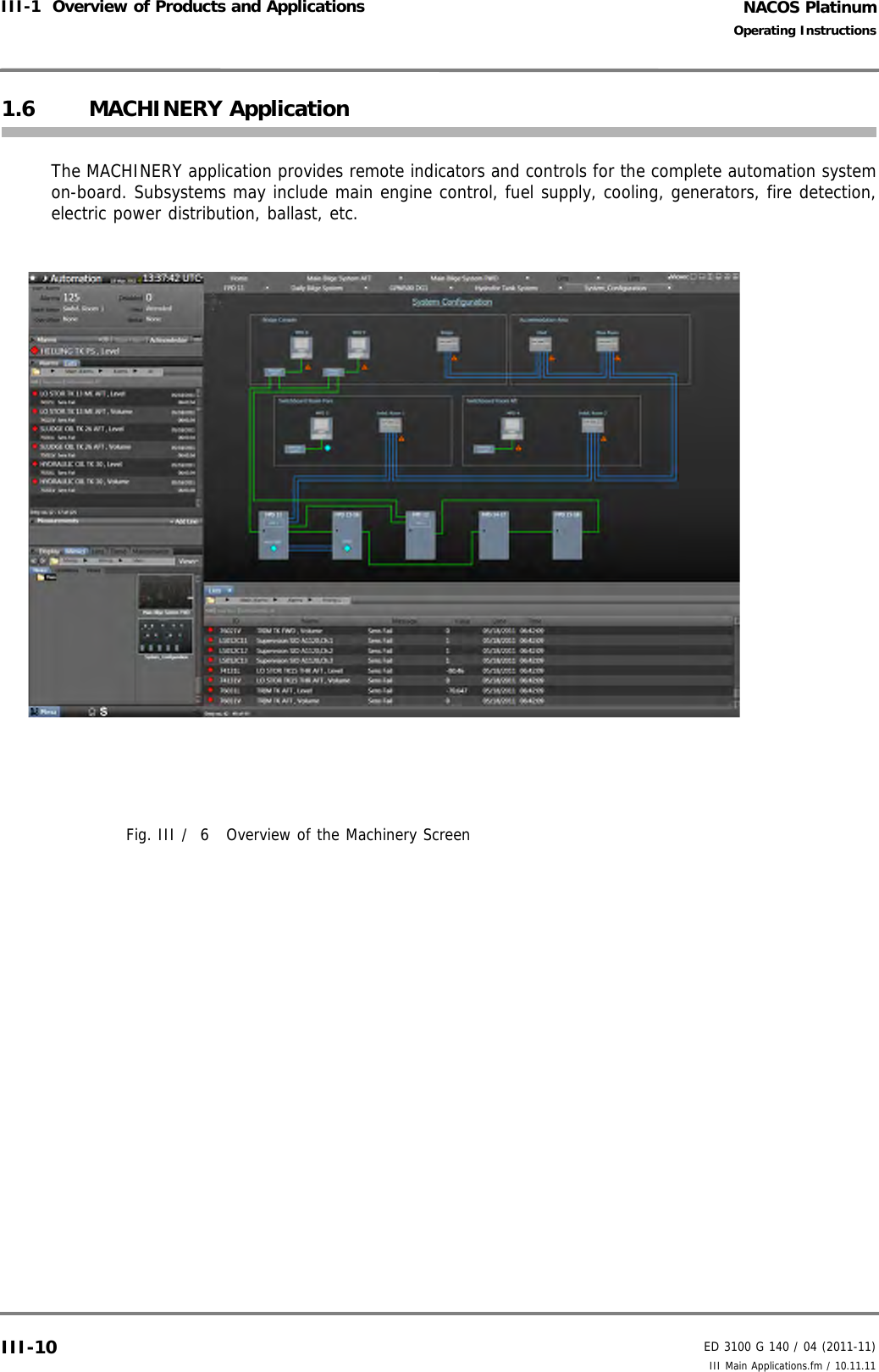
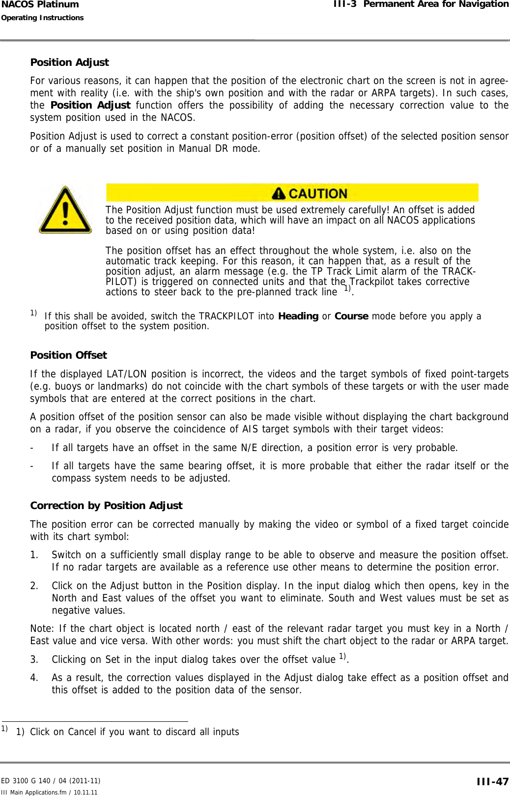
![NACOS PlatinumED 3100 G 140 / 04 (2011-11)Operating InstructionsI-5 NACOS Platinum Graphical User Interface I General.fm / 10.11.11I-625.5 Tabbed PanelsIn the NACOS Platinum applications, information are in many cases grouped on so-called tabbed panels.Tabbed panels are screen pages which are arranged on top of each other like a pile of paper sheets.The tabs identify the panels, and they are used to navigate through the panels. The picture below showsan example: Fig. I / 25 Example: Machinery screen with tabbed panels in three framesThe active tab is displayed in the foreground, and it is highlighted, which is e.g. indicated by a blue tab.The active tabbed panel has the so-called focus. That means that editing, e.g. entering values oradjusting the display, is only possible on that active tab. The other tabs are displayed as grey text sepa-rated with a vertical line. When you click on a hidden tab in the background, it is brought to the fore-ground and becomes the active tab. See table I / 25 above. You can also press [CTRL]+[TAB] on thekeyboard repeatedly to switch from tab to tab. In a multiple-frame-view, the other frames, which do nothave the focus, the front tabs are still highlighted by a grey tab but you will see that only one tab willbe active and have the focus. Active Tab Behaviour when Switching to Different LayoutsWhen you switch to a new layout type using the buttons (Layout Selector)the active tab has the following behaviour. If you switch to a layout type that has...- One more frame: the new frame becomes the active frame.- Two or three additional frames: the current active frame stays the active frame.- The same number of frames: the current active frame moves along with the switching behaviour.- Less frames: the current active frame remains the active frame unless it is the one which is closed.In that case the horizontally adjacent frame becomes active.In all cases the active tabbed panel will be highlighted, indicated by the blue tab.Note:Active TabForemost TabOther Tabs123Layout Selector](https://usermanual.wiki/SAM-Electronics/NG3051S30KW/User-Guide-1588887-Page-72.png)
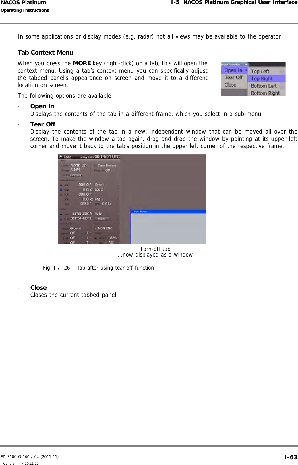


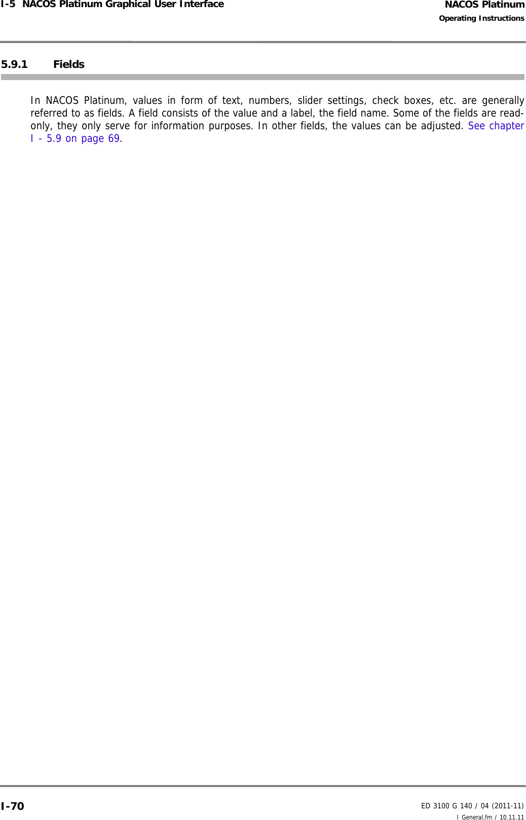
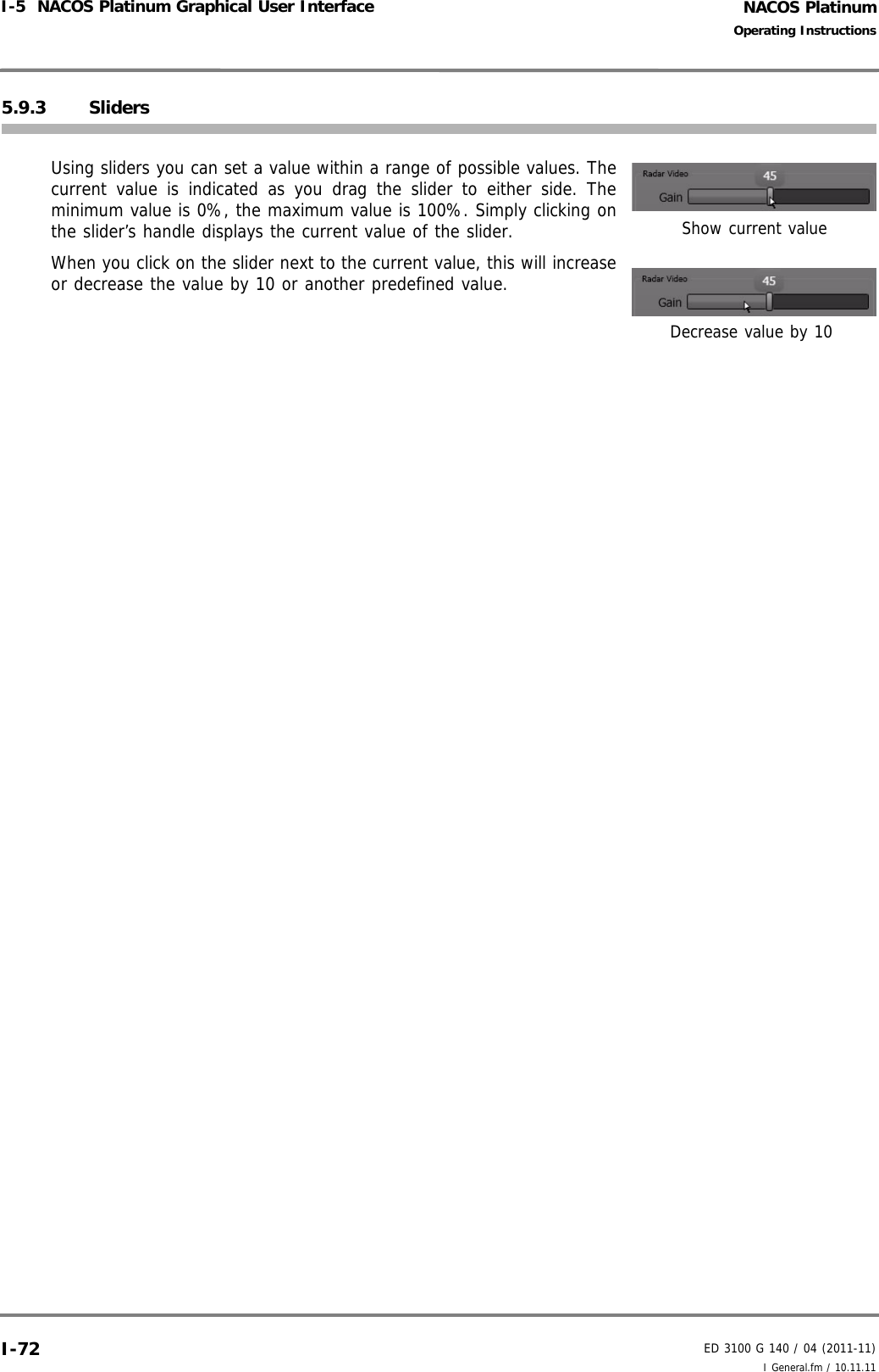
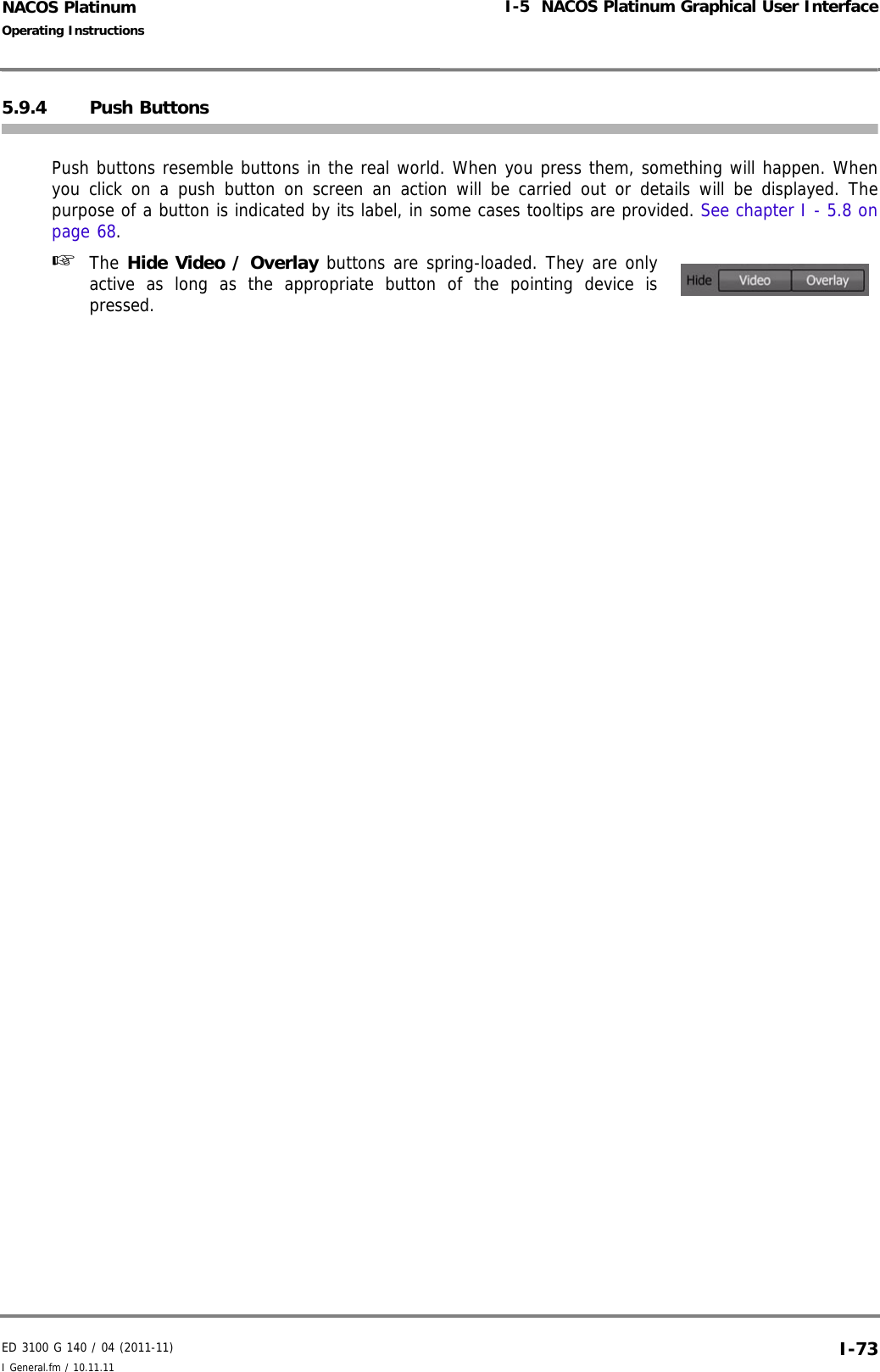
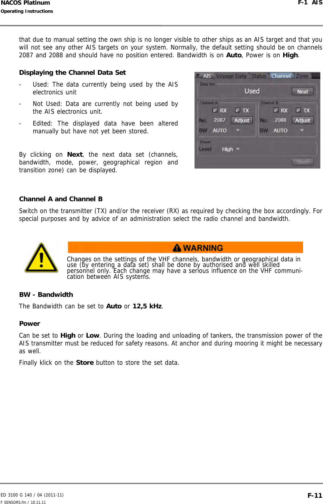
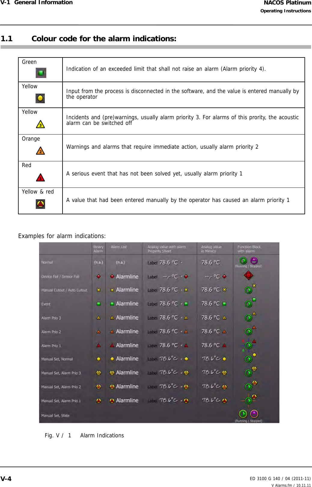
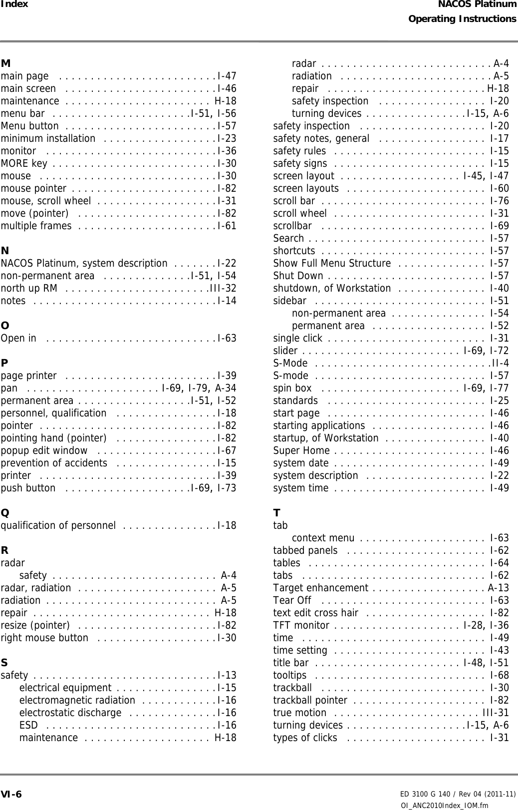
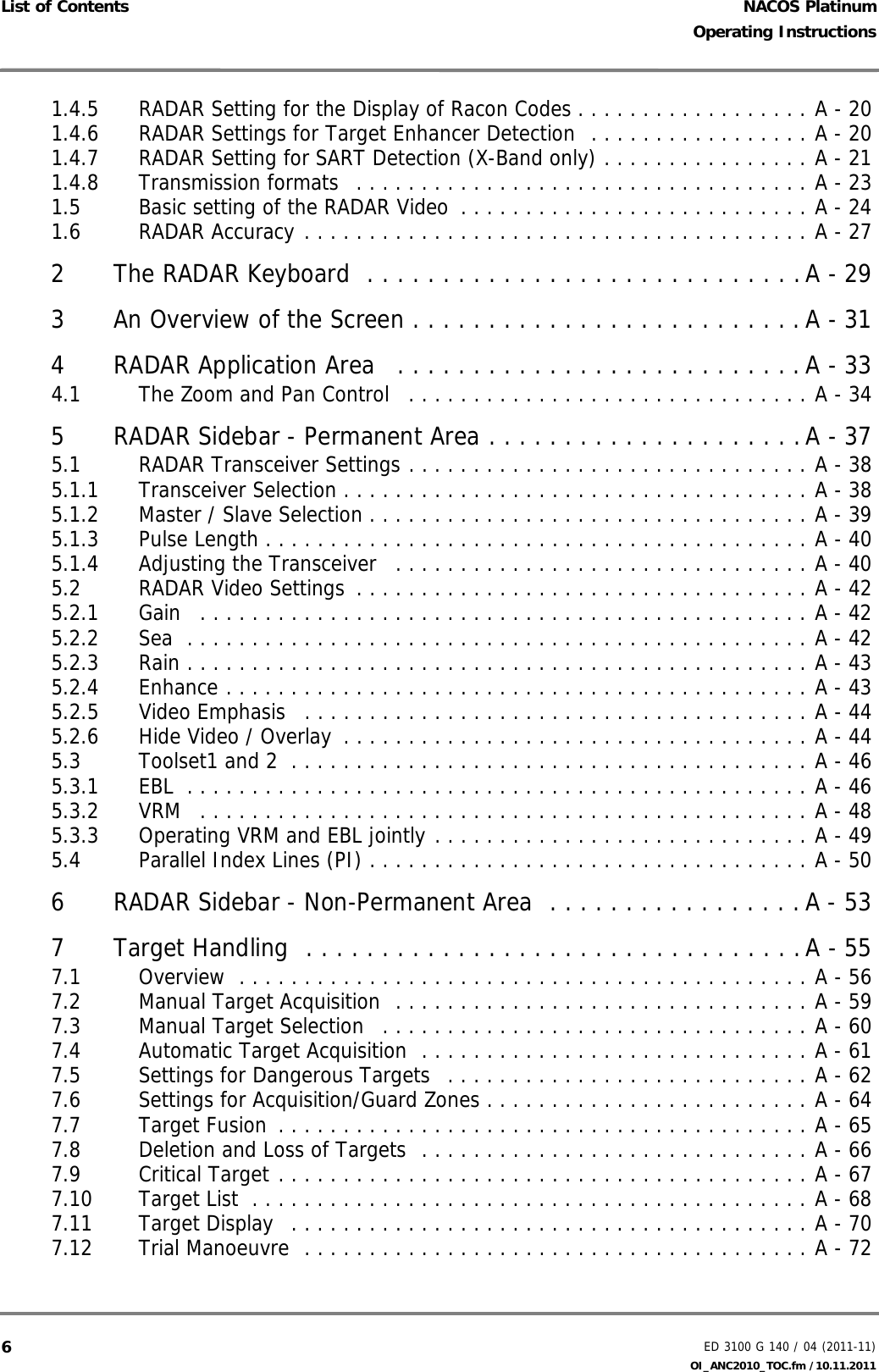
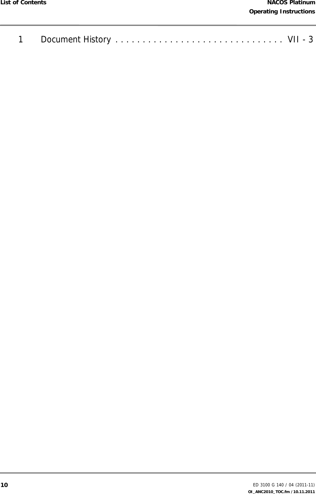
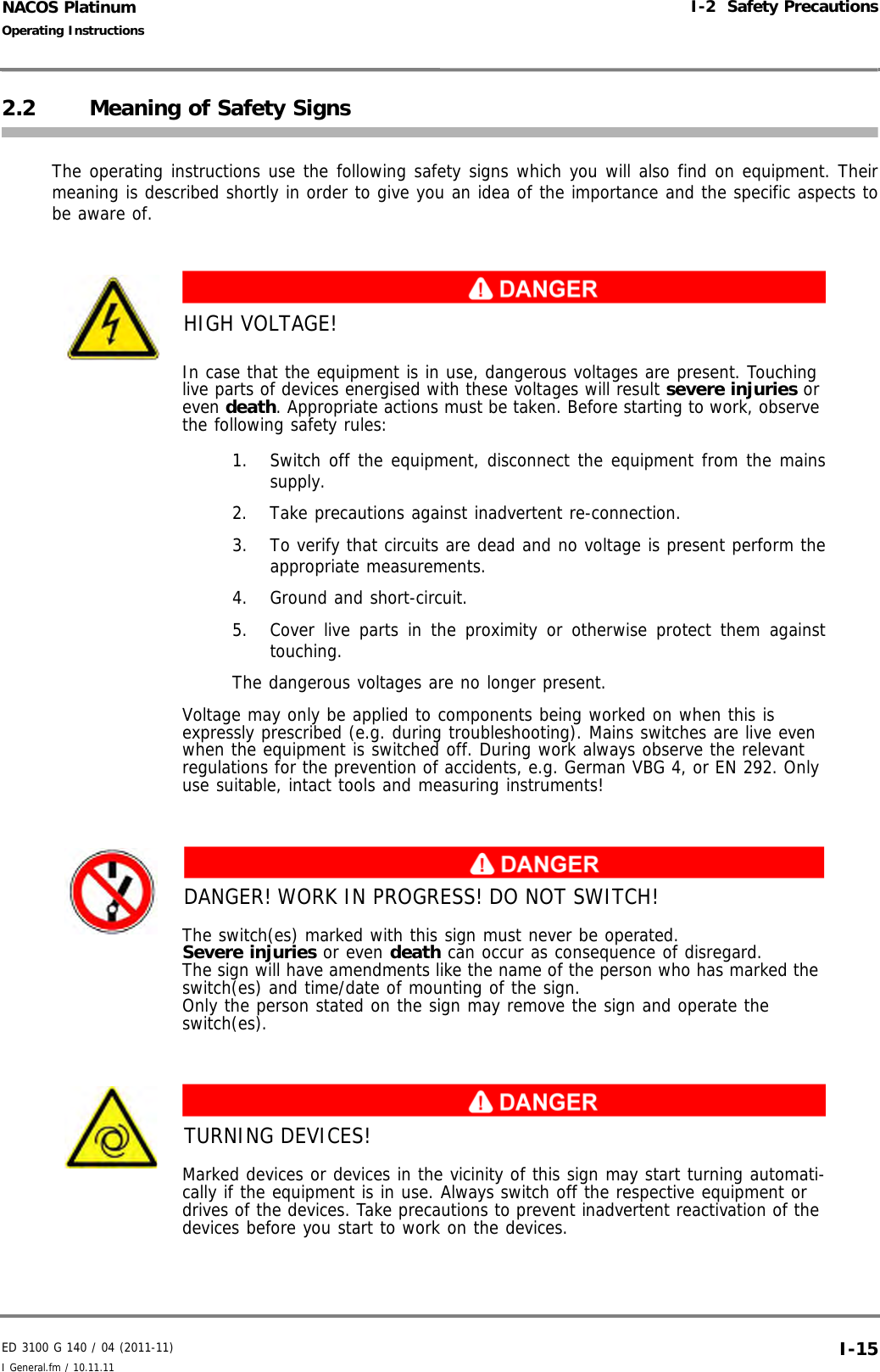
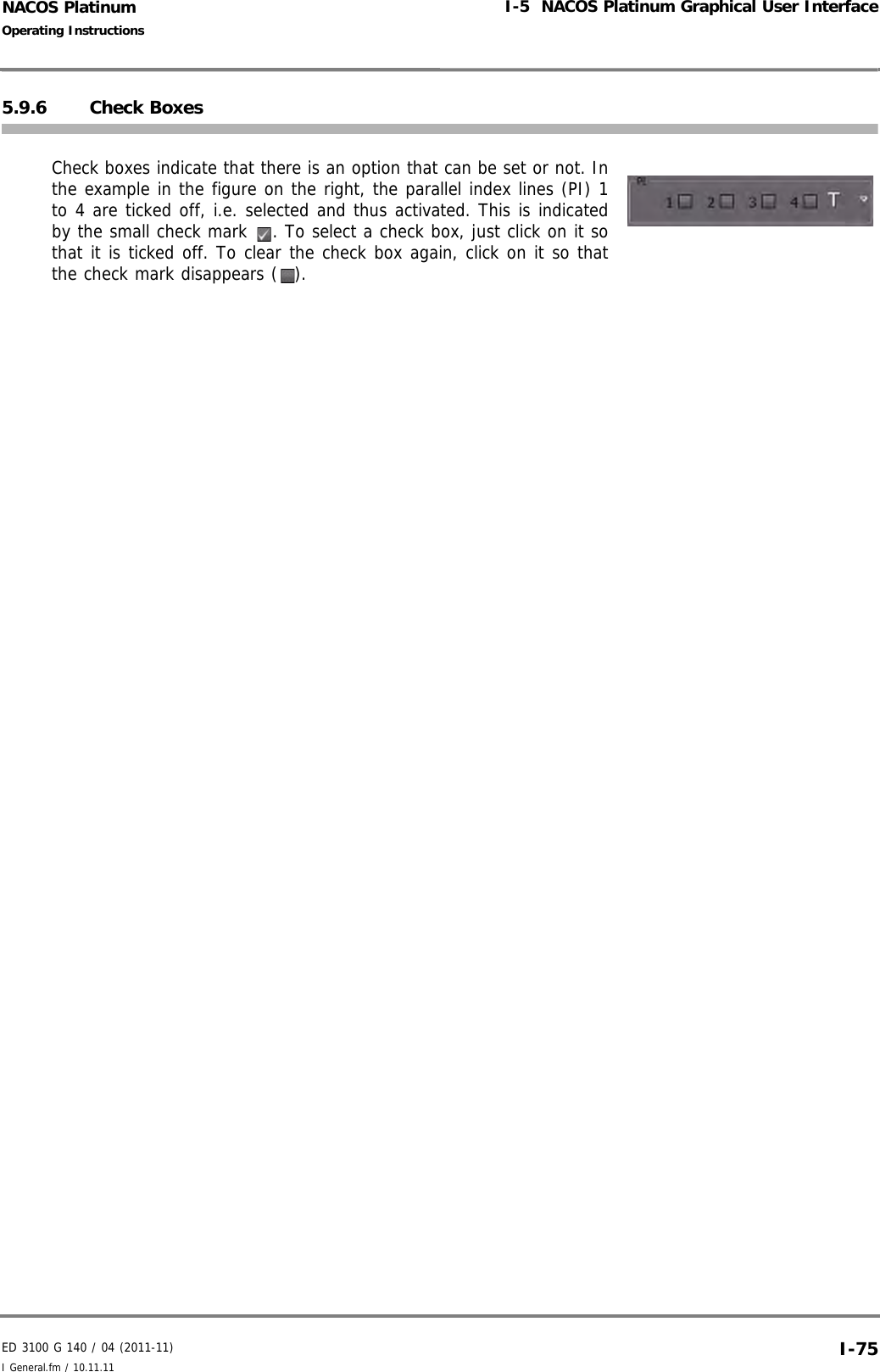
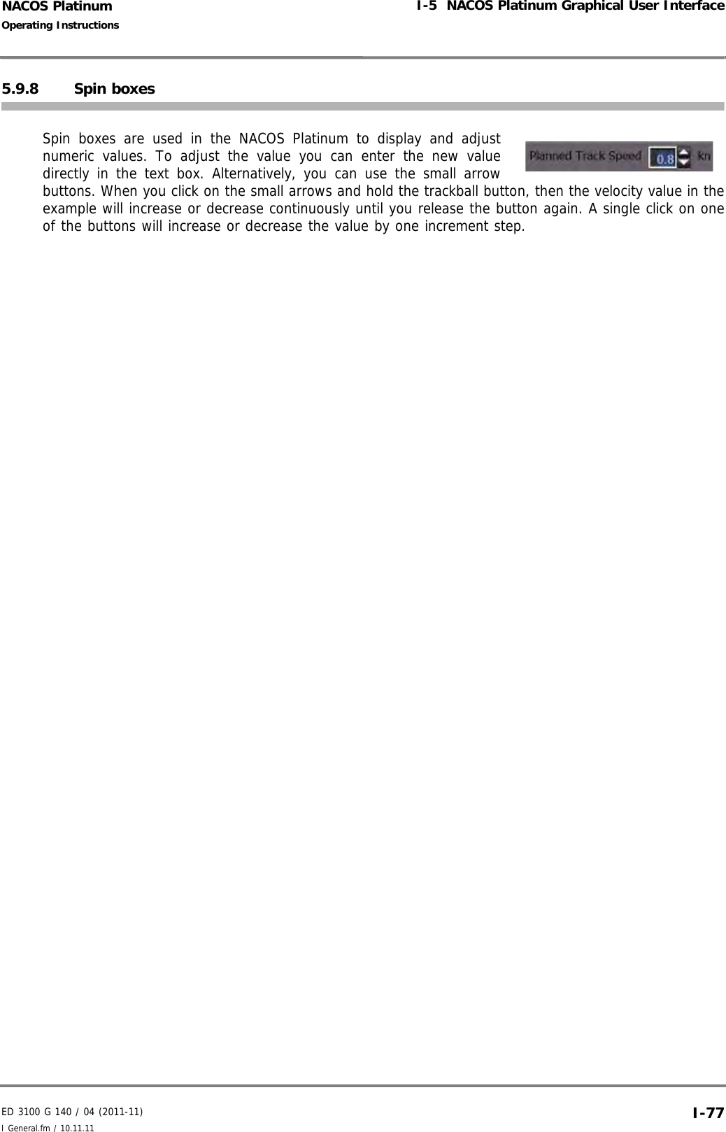
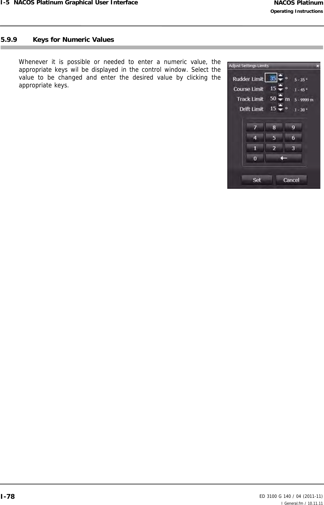
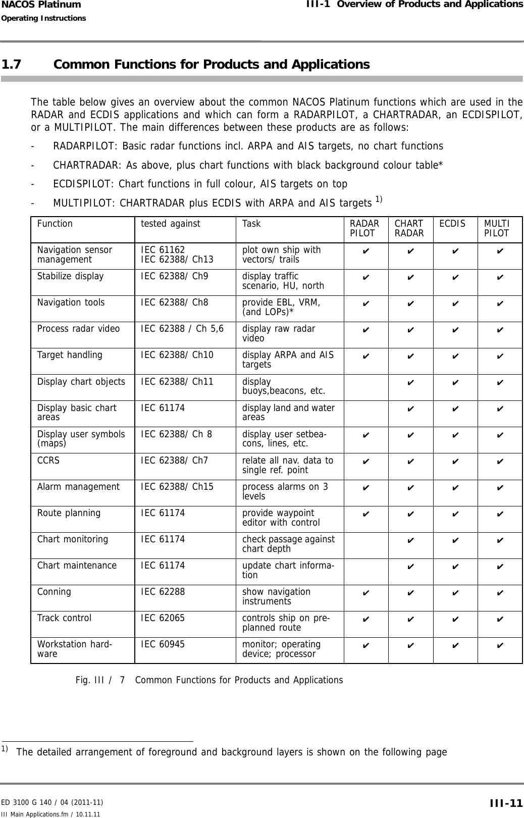
![NACOS PlatinumED 3100 G 140 / 04 (2011-11)Operating InstructionsI-5 NACOS Platinum Graphical User Interface I General.fm / 10.11.11I-745.9.5 Dropdown MenusDropdown menus are indicated by a small downward arrow next to afield. To open the menu, click on the arrow. To select different value forthe field, click the desired item on the dropdown menu. The field is thenupdated accordingly. To close the menu without making any changes,just click on any free area on screen or press the [ESC] button on thekeyboard.](https://usermanual.wiki/SAM-Electronics/NG3051S30KW/User-Guide-1588887-Page-84.png)
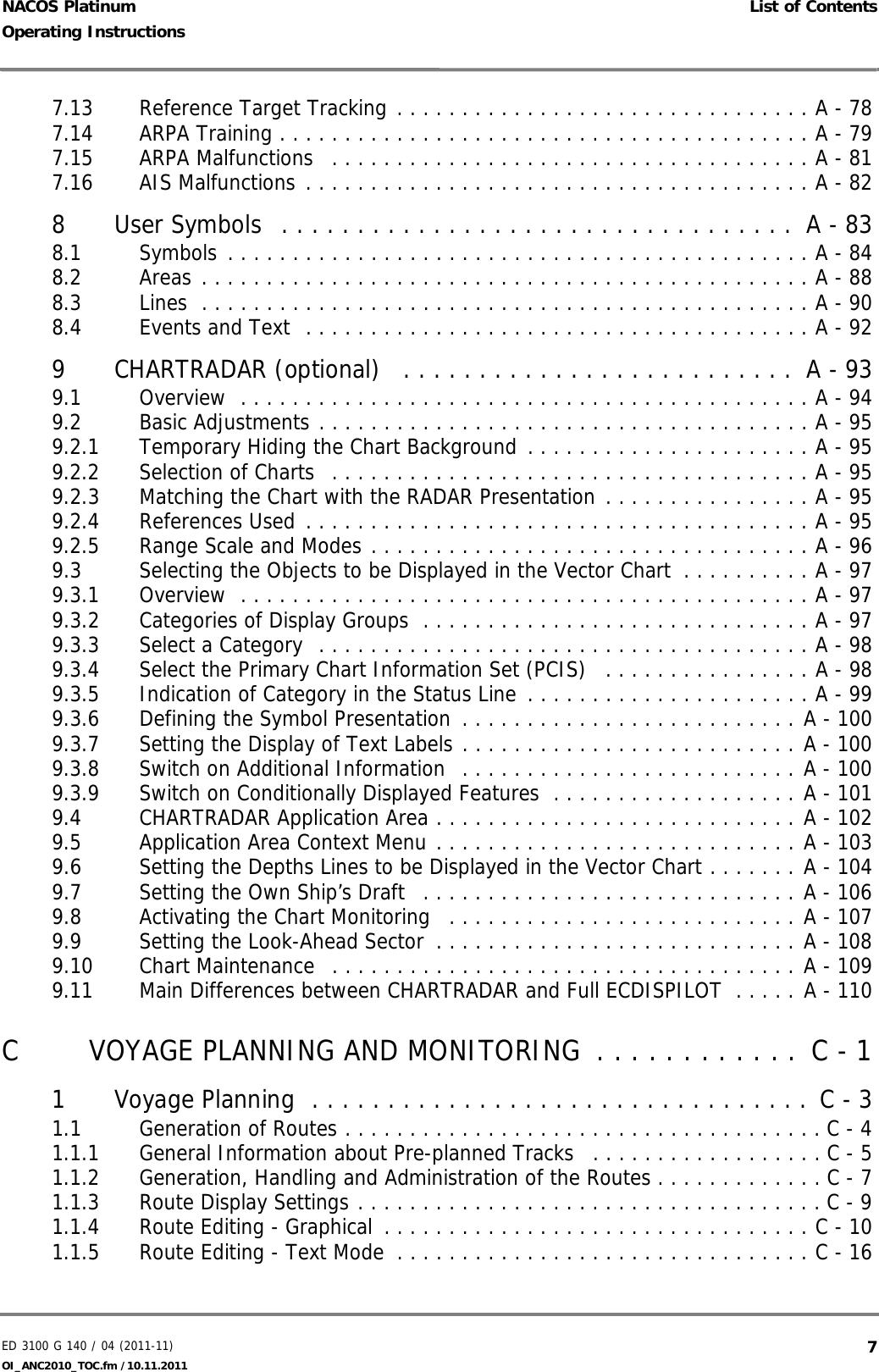
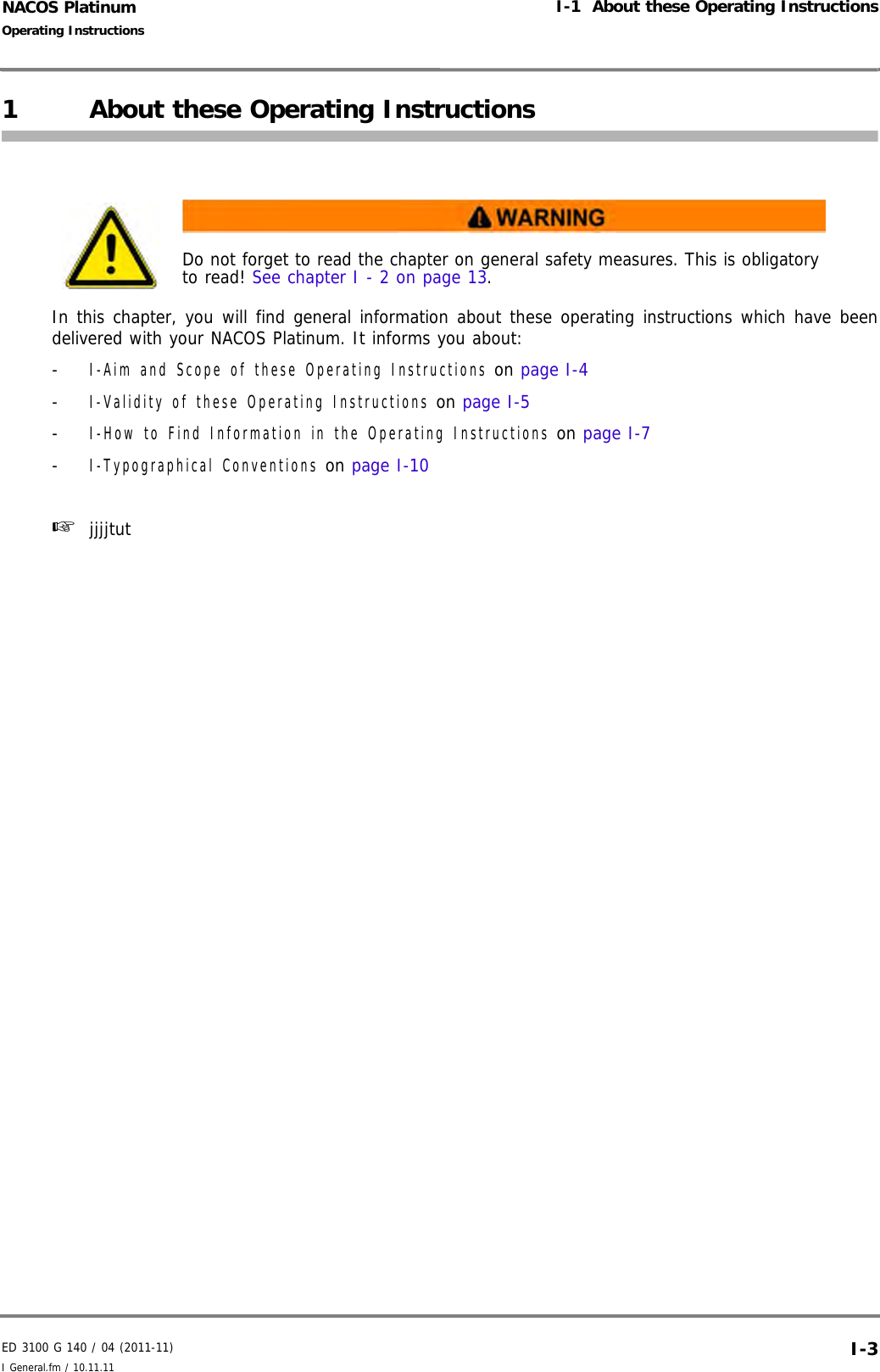
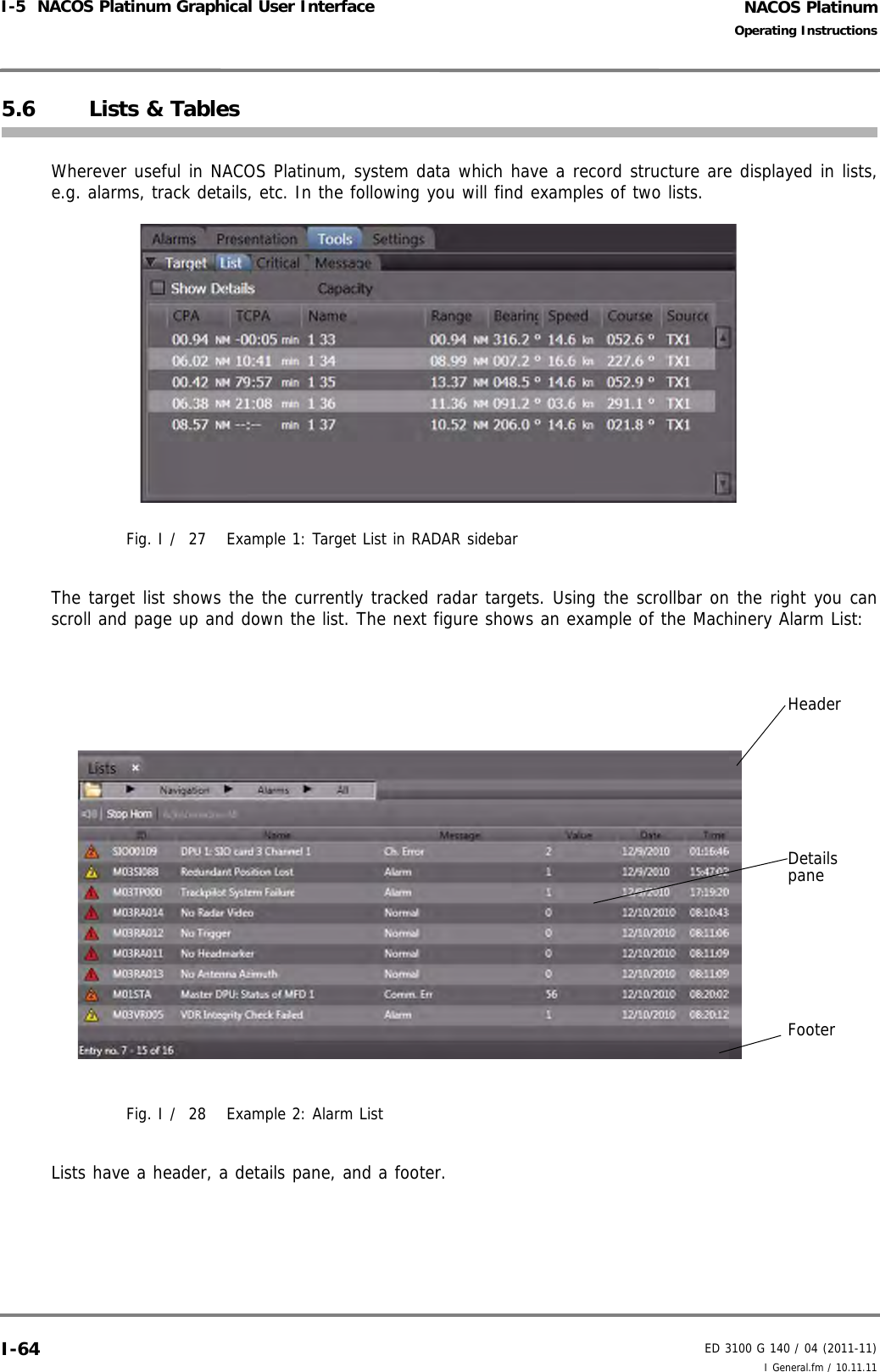
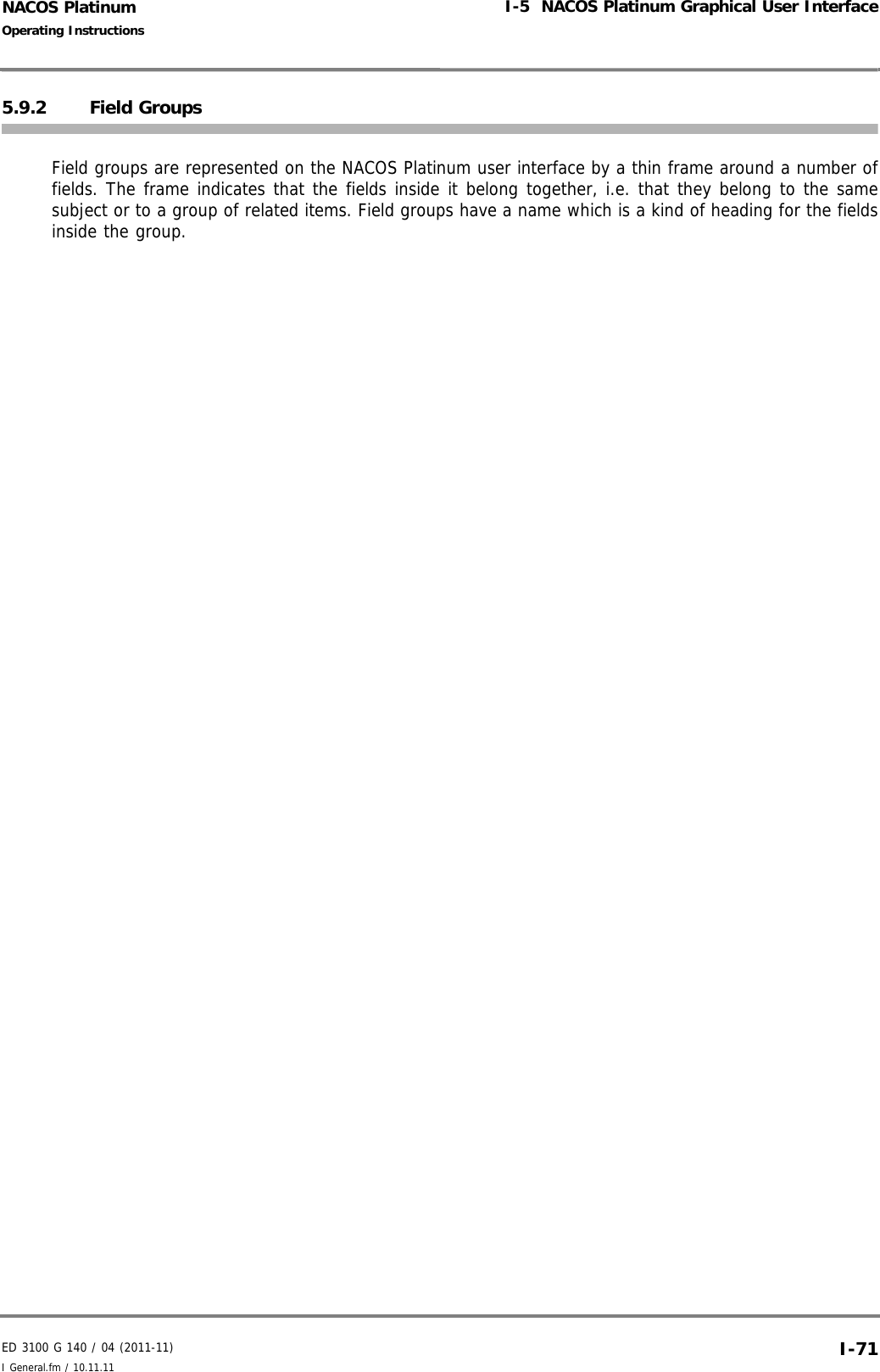
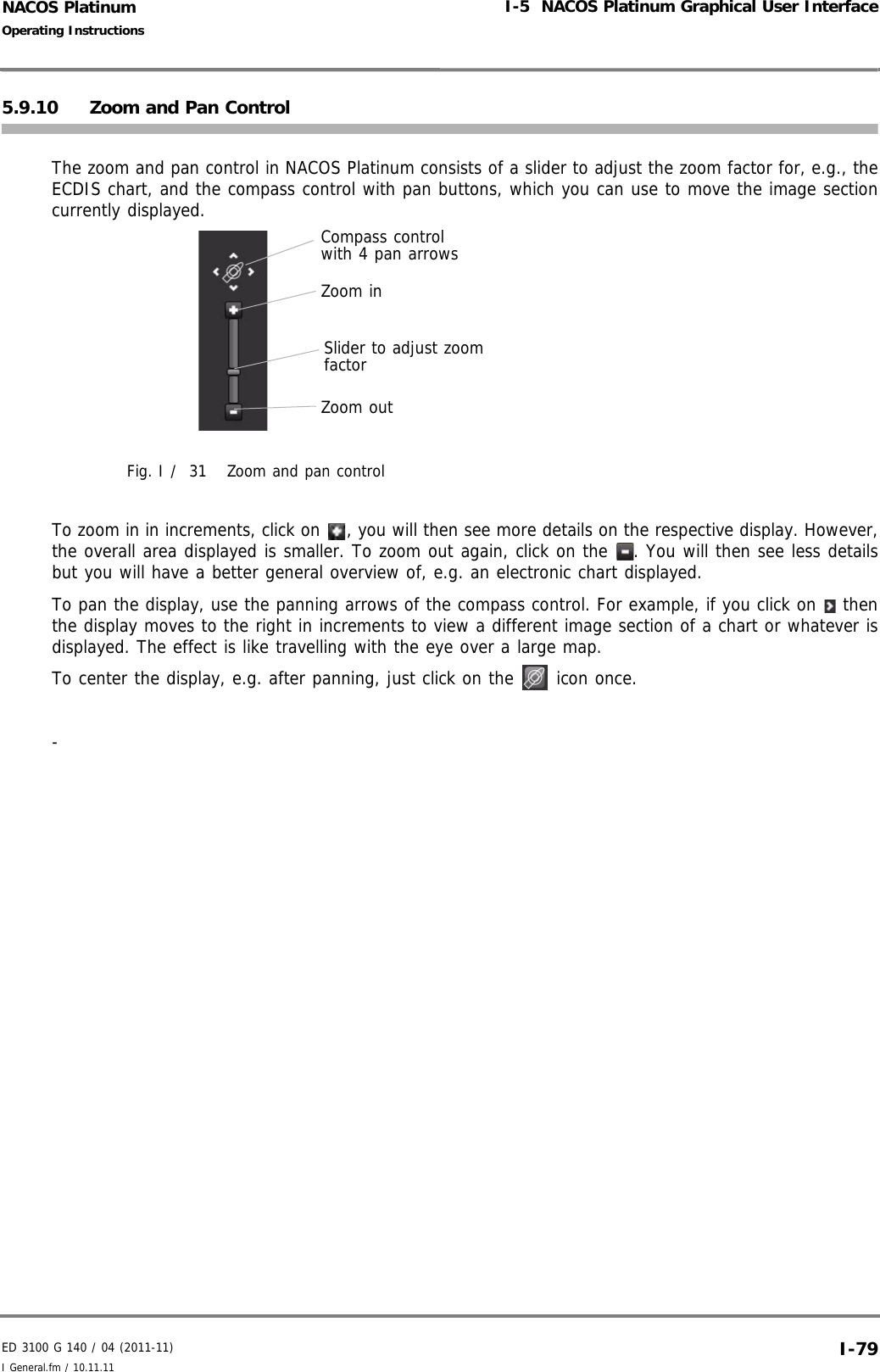
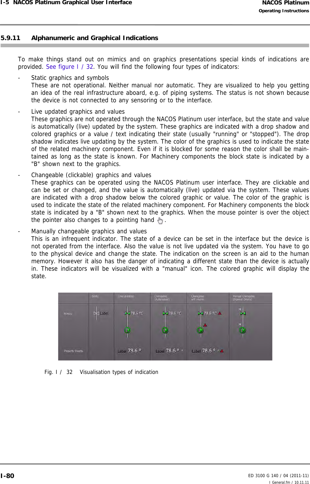
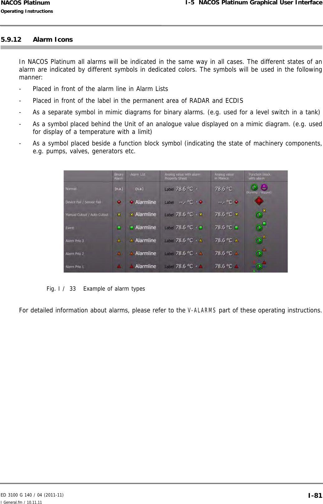
![NACOS PlatinumED 3100 G 140 / 04 (2011-11)Operating InstructionsI-5 NACOS Platinum Graphical User Interface I General.fm / 10.11.11I-765.9.7 Scroll BarsScroll bars are displayed when contents do not fit on the screen or sidebar etc. You can then use scrollbars to move the display up and down or sideways to view hidden parts. To scroll the display in small steps you can click on the scroll arrows at the end of the scrollbar. To pagethrough the display in larger steps click on the scrollbar or drag the scroll box. Alternatively you can usethe navigation keys of the computer keyboard, e.g. arrow keys or [PAGE UP] and [Page DOWN] forvertical scroll bars.](https://usermanual.wiki/SAM-Electronics/NG3051S30KW/User-Guide-1588887-Page-86.png)


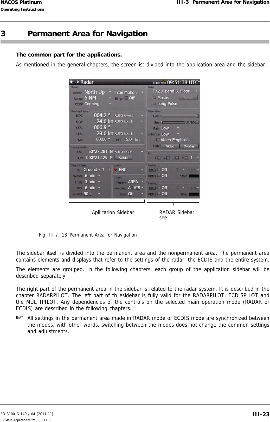


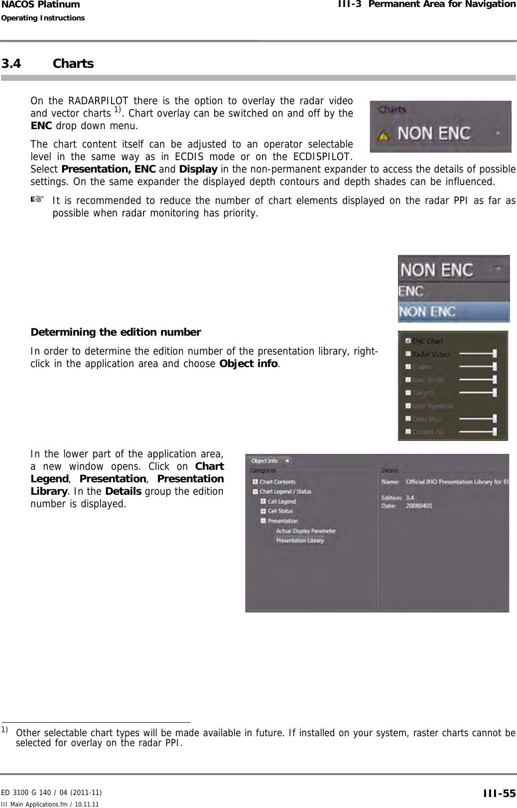
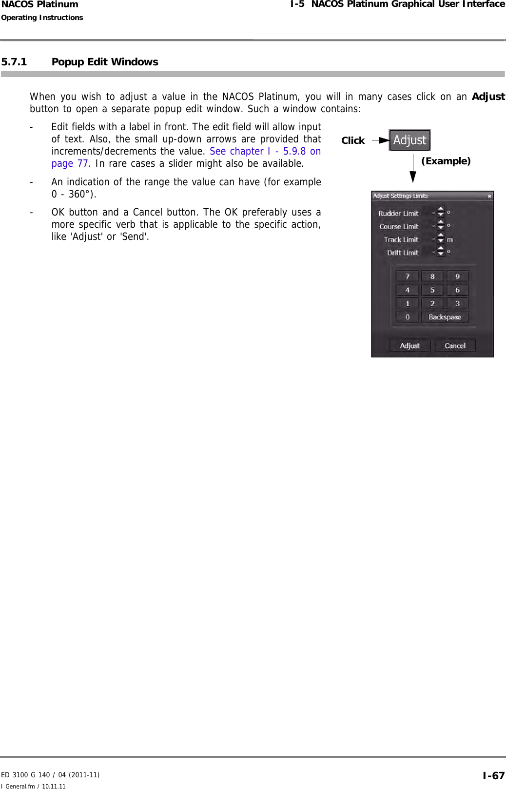
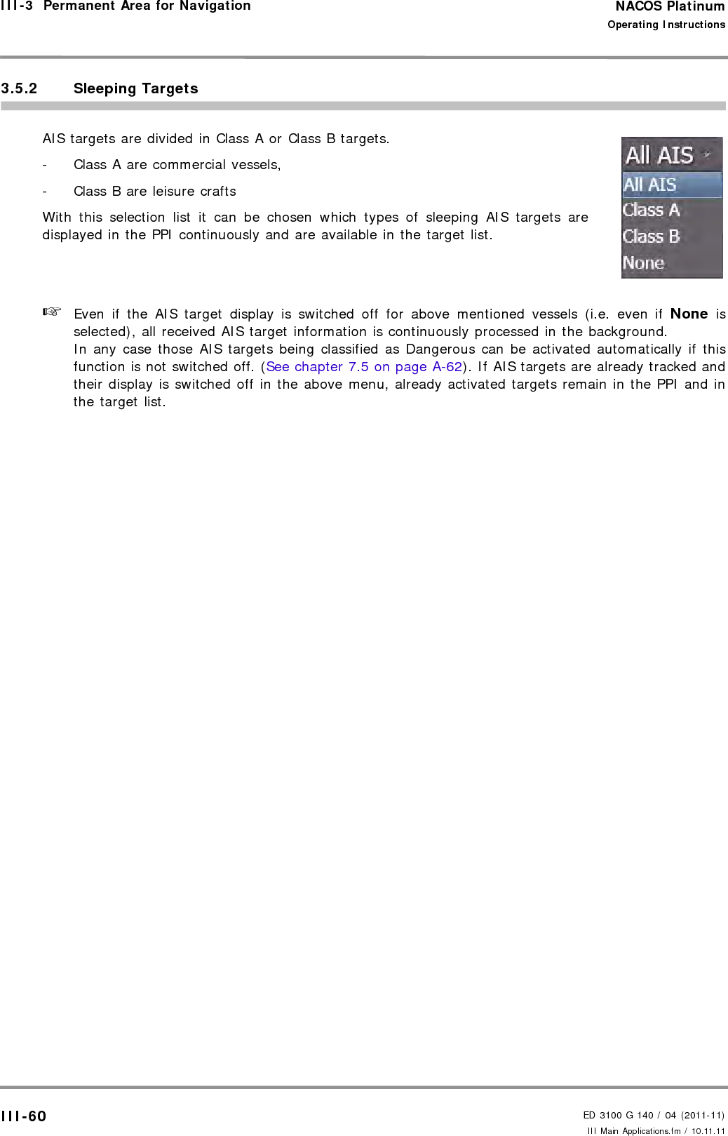
![NACOS PlatinumED 3100 G 140 / 04 (2011-11)Operating InstructionsIII-3 Permanent Area for Navigation III Main Applications.fm / 10.11.11III-563.4.1 The Chart Status LineFig. III / 16 The Chart Status LineTitleChart: The Chart Status Line is always visible if a Vector Chart Application is active, e.g. in ECDIS aswell as in Chartradar modeWarningNon ENC (incl. yellow warning symbol), this is only visible if the ENC vector charts on screen and atleast one part of the screen is filled with data from a "Non Official Vector Chart".In the Cursor-Tool-Tip of this part of the screen the text: "Non-HO data may not be used for navi-gation. Please refer to paper chart." will be visible in that part of the screen.Category- Standard is the IHO Standard selection for visible chart objects- Base is the IHO Definition for the minimum required selection of visible chart objects- All means that all chart objects are visible, except objects for data quality indication (data qualityobjects mostly overwrite the whole screen, therefore a special button exists in the presentationmenu)- Customized means that the user´s selection of visible chart objects is displayedIf in the Customized mode at least one visibility group is switched off, then the appropriate modeand an additional '-' character will be displayed.If in the Customized mode at least one visibility group is added, then the appropriate mode andan additional '+' character will be displayed.In the Cursor-Tool-Tip of this part of the screen the details of the actual selections are displayed.Date DependentAlways: Is only visible if in the presentation menu the selection button "Date Dependent" is set to"Always".In the Cursor-Tool-Tip of this part of the screen the text: "Date dependent objects are alwaysvisible. Information displayed may be incorrect for the present date and time." will be visible.Depth[m]: The actual units for chart depth values belonging to the chart cell at the own ships position in Trueor Relative Motion mode or at the center position of the chart area in Browse mode.Title Warning Category Date Dependent Depth Status](https://usermanual.wiki/SAM-Electronics/NG3051S30KW/User-Guide-1588887-Page-156.png)


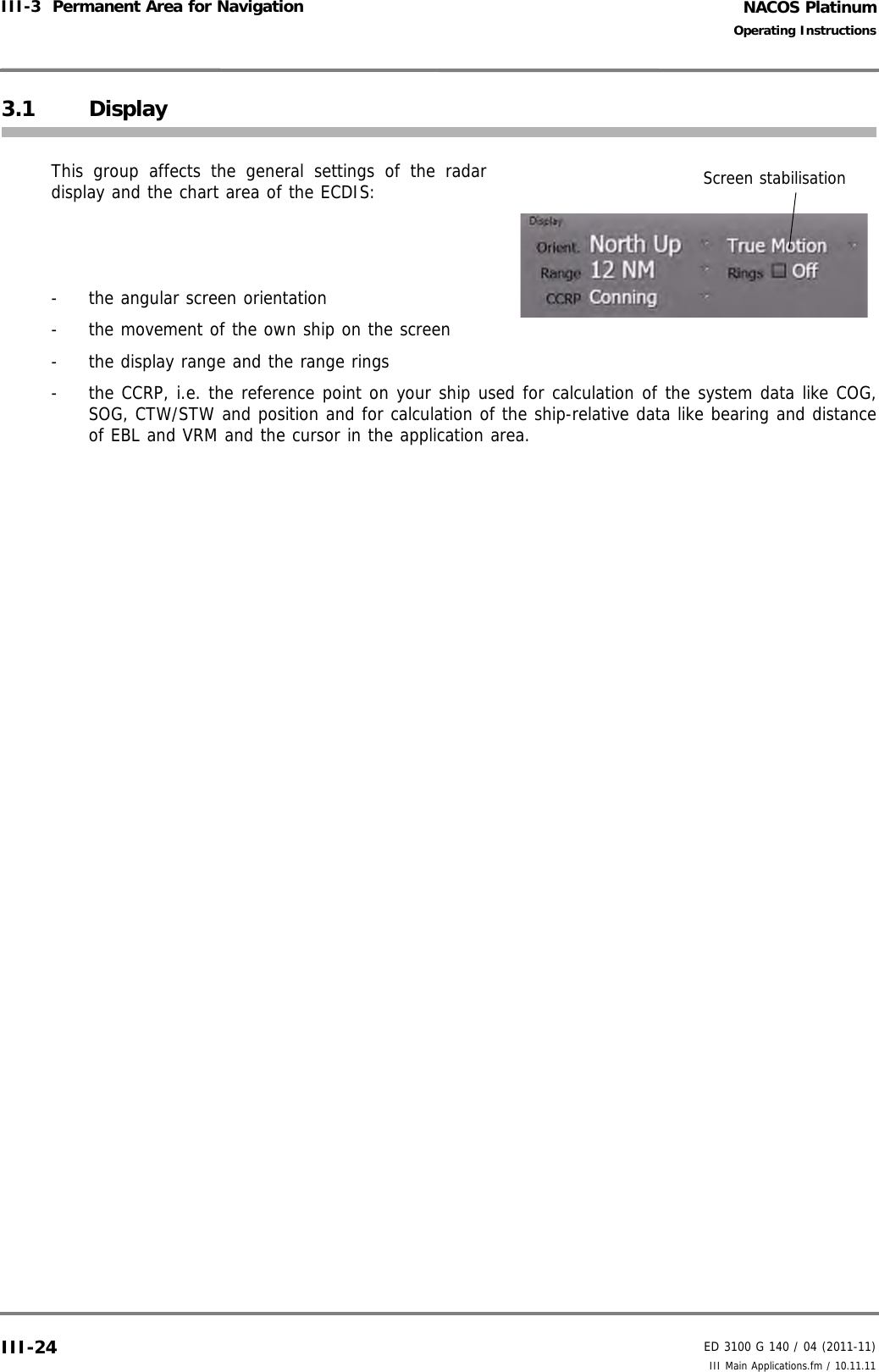
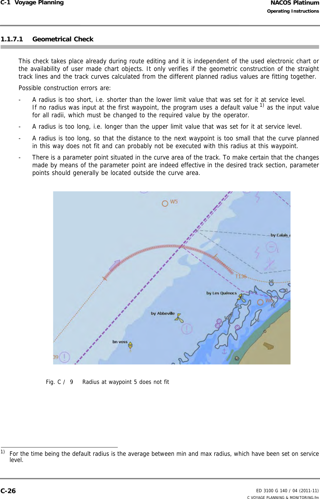
![NACOS PlatinumED 3100 G 140 / 04 (2011-11)Operating InstructionsC-1 Voyage Planning C VOYAGE PLANNING & MONITORING.fmC-20If the data input verification results in an error state, you will be asked by the system to change yourdata entry.Some of the columns do not have alphanumeric entries but - a selection menu (ETA/ETD: Arrival, Departure) or - a check box or- a selection bar (ECON).Predefined Radius- Already during editing the route, it is advisable to enter a radius for the first waypoint. This radiuswill be copied to all other added waypoints until you set another radius. In this way it can be verified"on-line" during editing if geometric constraints (matching of length of the legs, radius, and amountof course change) are violated.- It is recommended first to use a sort of "default" radius for sailing with nominal speed which couldlater be adjusted for your needs and depending on the results of the verification of the route on thechart display. The default radius should create a rate of turn far below the maximum rate of turnyou would normally accept for your ship under the planned loading conditions.- The predicted steady state turn-rate at a waypoint caused by the planned radius can easily be esti-mated by the calculationROT [°/min] ~ sailing speed [kn] / radius [NM]Table C / 1 Route Editing - Predefined RadiusSpeed Radius ROT [estimated]25 kn 1.00 NM ~ 25 °/min25 kn 0.50 NM ~ 50 °/min12 kn 1.00 NM ~ 12 °/min10 kn 0.10 NM ~ 100 °/minBe sure not to plan too small Radius values at high speed which would cause too high and possibly dangerous turn-rates on your ship. 1)1) The maximum ROT and the minimum allowed radius at nominal speed should have beendefined during the sea trials. Both values are parameters of the system configuration on servicelevel. The radius input during route planning is limited by the parameters min. and max. radius.](https://usermanual.wiki/SAM-Electronics/NG3051S30KW/User-Guide-1588887-Page-292.png)
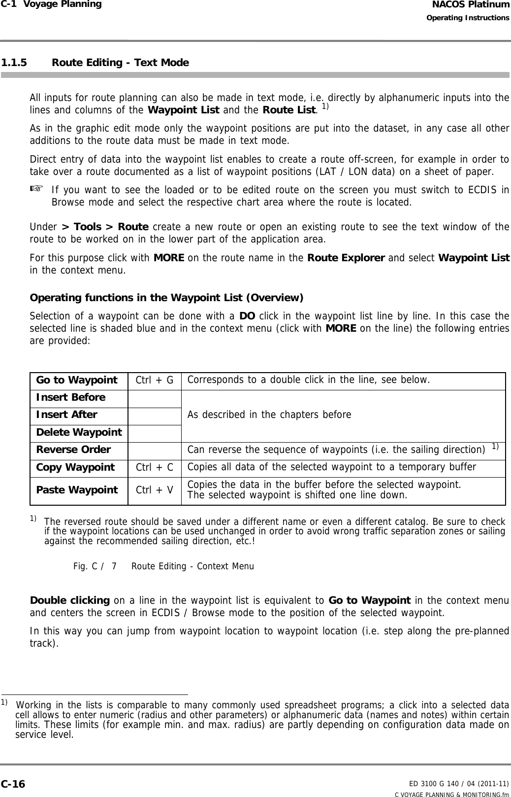
![NACOS PlatinumED 3100 G 140 / 04 (2011-11)Operating InstructionsC-1 Voyage Planning C VOYAGE PLANNING & MONITORING.fmC-221.1.6 Details of the Waypoint DataThis section gives an overview about the meaning and use of all parameters and data being part of theroute data-set. The shortcuts in parenthesis [ ] are those used in the headlines of the Waypoint andRoute List on the screen.Waypoint Number [No.]Meaning: Serial number of a waypoint within the route; it is automatically allocated consecutively by theprogram, beginning at 1. It clearly identifies the waypoint within the route. It appears as a referencemarker in all lists, in the chart area (if switched on), and in all other displays of the system which referto the individual waypoint.Name of the Waypoint [Name]Meaning: Helps to identify the waypoint during the subsequent processing and during use while sailingalong the route. It can be displayed or printed out in all lists, and can be shown in most displays of thesystem which refer to the individual waypoint.Waypoint Position [LAT] [LON]Meaning: Geographical WGS84 position of the waypointEditing: In the [LAT] and [LON] column.Special features during editing: The hemispheres are input with N, S and E, W.Radius [RAD]Meaning: Radius in nautical miles with which the planned course change manoeuvre at a waypoint is tobe performed. It can be set between the minimum and maximum radius value defined for the systemon service level.Estimated Time of Arrival / of Departure [ETA/ETD]Meaning: Indication of the manual set or automatically calculated estimated time of arrival or departuretime depending on the ET Mode set in the following column. Estimated Time Mode [ET Mode]Meaning: Defines the method how the ETA/ETD data are calculated by the system.Editing: Under ET Mode in the Waypoint List; can be set to Departure / Arrival / Calculated. If it is set to Calculated, no input can be made into the ETA/ETD column. If you do not want to use thePlanned Track Speed function, the point of departure should be set to Departure, any point of arrivalshould be set to Arrival. Parameter Point Attribute [PP]Meaning: With the aid of a waypoint for which the Parameter Point attribute is set, new values for theroute parameters Maximum Speed, Course Limit, Off Track Limit and Rudder Economy can be set differ-ently within a straight track segment (the leg of a route).](https://usermanual.wiki/SAM-Electronics/NG3051S30KW/User-Guide-1588887-Page-294.png)
![ED 3100 G 140 / 04 (2011-11)Operating InstructionsC-1 Voyage PlanningC VOYAGE PLANNING & MONITORING.fm C-23NACOS PlatinumWaypoint Notes [Notes]Meaning:Here, you can input information and instructions for the nautical personnel, which can be displayed onthe MFD while the ship is sailing on the leg to this waypoint. The consecutive waypoint notes shown on the screen can be used as an automatic notebook or can alsobe printed on in different list formats 1).These waypoint notes, on operator request, also appear in the Chart Information Window on thechart (together with other waypoint related data). Note:If you use an alphanumeric keyboard during editing, in the Notes window you can "cut and paste" thetext or parts of it for use in the same route for another waypoint (cut = Ctrl+C; paste = Ctrl+V).From and To Waypoint [From - To]Meaning: This column indicates the numbers of the From and To Waypoints, i.e. the leg designationbetween waypoint N and N+1. The columns following in the same line in the Route List are valid for thisleg.Waypoint Distance [DIST]Meaning: This column indicates the distance in nautical miles between two consecutive waypoints, i.e.the length of the track segment between the From-waypoint and the To-waypoint. The calculationincludes the curved track line defined by the radius and the course change at the waypoint.Waypoint Bearing [BRG]Meaning: This column indicates the bearing of the track line between two consecutive waypoints, i.e. thecourse over ground to be steered on the straight part of a track segment.Calculated Speed [calc. SPD]Meaning: This is the speed that is calculated for the track segment between two consecutive waypoints;it is calculated once for the Planned Speed mode or continuously in ETA Mode. - In ETA mode (i.e. an arrival time has been set): While the ship is sailing along the track, this speed is continuously computed and limited on the basis ofthe Max. Speed values. - In Planned Speed mode (i.e. the Planned Track Speed has been set): After the planned speed value has been Set by the operator, this speed is computed once for each leg,whereby the calculated values are limited by the Max. Speed values.In any case the Calculated Speed is the speed with which the ship will have to sail in order to reachthe destination at the planned estimated time of arrival and which can be used as the speed setting bythe optional SPEEDPILOT in Arrival Mode.Because the Calculated Speed is continuously shown in the Route List display window, it can also beadopted as a set point for the manual speed setting via the propulsion lever by the officer of the watch.1) Printing functions and Waypoint Notes displays are not yet available in the system.](https://usermanual.wiki/SAM-Electronics/NG3051S30KW/User-Guide-1588887-Page-295.png)
![NACOS PlatinumED 3100 G 140 / 04 (2011-11)Operating InstructionsC-1 Voyage Planning C VOYAGE PLANNING & MONITORING.fmC-24Maximum Speed [MAX SPD]Meaning: The Maximum Speed defined for a leg is used by the system as the speed limitation for theCalculated Speed between each From waypoint and To waypoint (i.e. each leg). This limitation by the MAX SPD values takes place leg by leg with manual setting of the Planned TrackSpeed as well as during the frequent recalculation in ETA mode.Course Limit [CRS LIM]This route parameter is only relevant in systems equipped with a TRACKPILOT.Meaning: Alarm limit of the TRACKPILOT for the difference between set course and actual course (thecourse deviation). It also influences the possibility of switching the TRACKPILOT over to Track mode andthe corrective actions performed by the TRACKPILOT if the ship deviates from the track, see chapter "G- TRACKPILOT" on page G-1.Track Limit [XTD LIM]Meaning: Alarm limit of the system for the deviation from the route (the off-track distance to the trackline is indicated as XTD in meters). The track limit also influences- the ECDIS monitoring, see Section 4.4- the checking of deviations from the System Route.- the possibility of switching the TRACKPILOT over to Track mode,- the control precision of the TRACKPILOT in Track mode, - the filtering and monitoring of the external position-data by the TRACKPILOT in Track Mode.Sailing Mode [Sail]Meaning: This setting specifies whether the track segment between two waypoints is to be computedand used as the basis for steering with the TRACKPILOT and displayed on the chart as a Great Circleor as a Rhumb Line. The default setting defined by the program is the Great Circle mode (a new route starts with GC modeon each leg). In contrast to a Rhumb Line, which is steered with constant course, on a Great Circle trackthe entire distance is shorter and small course changes are about to happen when the ship is followingthe pre-planned GC track. Rudder Economy [Eco]Meaning: Optimization of the TRACKPILOT between precision of control and frequency of rudder move-ment, depending on the prevailing conditions like the sea state and the wind. Low values for Eco meanshigh rudder gains and vice versa (see chapter "G - TRACKPILOT" on page G-1).To simplify manual adjustments during use of the TRACKPILOT, this value should only be entered forthe first waypoint and at the boundary between a protected area (harbour, river, canal) or other confinedwaters and an unprotected area (open sea).](https://usermanual.wiki/SAM-Electronics/NG3051S30KW/User-Guide-1588887-Page-296.png)
![NACOS PlatinumED 3100 G 140 / 04 (2011-11)Operating InstructionsC-1 Voyage Planning C VOYAGE PLANNING & MONITORING.fmC-32Time Schedule with Planned SpeedIn order to adapt the initial time schedule of the route to a constant speed for the entire route or to aspecified speed profile, perform the following steps: 1. Select the arrival point and in its ET Mode field set the mode to Calculated.2. Verify or change the maximum speed values in the MAX SPD fields according to your needs.3. In the Planned Speed field enter the required speed value and click on Set.This will result in a new calculation of the time schedule for the entire route based on the set departuretime and the planned speed value, but taking into account those legs which have a speed limitation setby the MAX SPD values.If the route contains an arrival point in the ET column and the Planned Speed is entered, you will get awarning that this will be changed to Calculated and the arrival time is lost.With [Clear] you can make the Planned Speed invalid, so that the time schedule can be recalulatedbased on the set arrival and departure times.Notes: If the maximum speed is achieved in all calc. SPD columns, the arrival time cannot be made shorter.In this case an earlier arrival time will also lead to an earlier departure time. In the same way a laterdeparture will create a later arrival time.If you must achieve an earlier arrival time and an earlier departure is not possible, the MAX SPD valuescould be increased until an upper limit is reached, which is specific for your ship under the prevailingconditions.](https://usermanual.wiki/SAM-Electronics/NG3051S30KW/User-Guide-1588887-Page-304.png)
![ED 3100 G 140 / 04 (2011-11)Operating InstructionsC-1 Voyage PlanningC VOYAGE PLANNING & MONITORING.fm C-33NACOS Platinum1.1.8 Completing the Generation of the RouteThe new or modified route must be stored in the file system of the MFD so that the data that were inputduring or after checking of the route will not be lost as soon as the route is switched off or the systemis shut-down.Ending the Generation of a New or Modified RouteThe route window must be switched on and visible.1. You can enter additional notes to each single waypoint in the Note input fields of the waypoint list.2. In the header of the waypoint list or in the context menu of the Route Expander click on [Save]and the new or modified route data-set will be stored with all data which have been entered untilthen under the indicated Route Name.☞ If you have modified a route and want to keep the original route unchanged you must enter anotherroute name for the original route before you save the modified one. This is done by a MORE clickinto the catalog field of the Route Explorer where Save As... must be clicked. When specifyingthe route name, pay attention to the following:- Each route is assigned to a catalog. Within the catalog, the route is clearly identified bymeans of the route name, i.e. within a catalog the same route name can only be assignedonce.](https://usermanual.wiki/SAM-Electronics/NG3051S30KW/User-Guide-1588887-Page-305.png)