SAMYUNG ENC SRG-3150DN 150W DSC MF/HF Radio Telephone User Manual SRG 3150DN Rev 1 1 Manua Eng 080409
SAMYUNG ENC Co., Ltd 150W DSC MF/HF Radio Telephone SRG 3150DN Rev 1 1 Manua Eng 080409
UserManual.wiki
>
SAMYUNG ENC
>
SRG 3150DN User Manual
User Manual
Navigation menu
Upload a User Manual
Namespaces
Wiki Guide
HTML
PDF
Info
Views
User Manual
Discussion / Help
Navigation
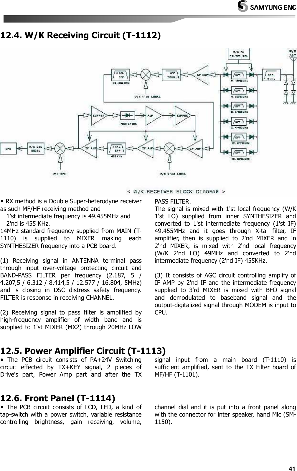
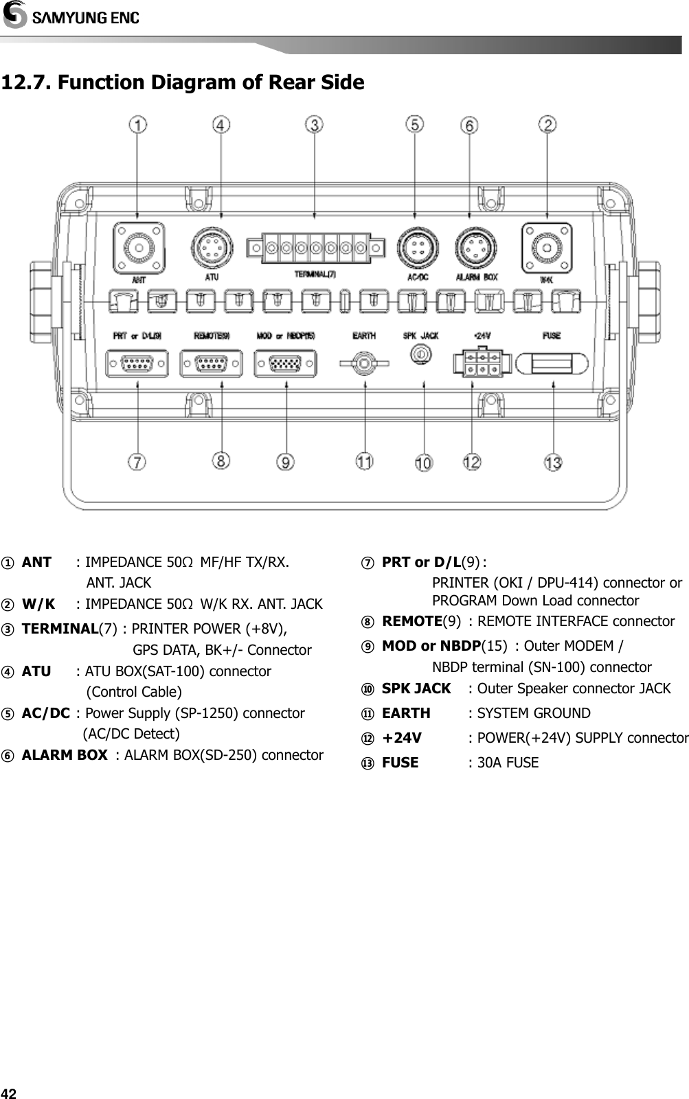
![312.6. Front Panel (T-1114) .........................................................................................41 12.7. Function Diagram of Rear Side ...................................................................42 Chapter 13. NBDP Terminal ............................................................................................... 43 13.1. NBDP Terminal Main Unit ..............................................................................43 13.2. Initial Display of Telex (NBDP) mode ........................................................43 (1) Initial screen function explanation ...............................................43 (2) Initial screen function button explanation ...............................43 (3) Control function in Keyboard .........................................................44 13.3. SettingUpTX/RX Frequency ...........................................................................44 (1) Setting TX frequency ..........................................................................44 (2) Setting Rx frequency ..........................................................................44 (3) Coast Radio Station TX/RX frequency set up .........................44 (4) Setting TX/RX Freq. by calling channel .....................................44 13.4. [ARQ] mode ..........................................................................................................44 (1) Connecting with the other station by ARQ mode. ..............44 (2) Connecting specific station .............................................................45 (3) Communication in ARQ mode ......................................................45 (4) Transmitting file ....................................................................................46 (5) Transmitting of Macro Command ................................................46 13.5. [FEC] mode ............................................................................................................46 (1) Connecting the other station by Selective FEC mode. ......46 (2) Connecting with the other station by collective FEC mode. .......47 (3) Communication in FEC mode ........................................................47 (4) Receiving of FEC mode .....................................................................47 (5) Transmitting file ....................................................................................48 (6) Transmitting of Macro Command ................................................48 13.6. Other sea station or ship station edit & resister frequency ..........48 13.7. Station print (Counter party & Frequency print) ................................49 13.8. Registration of macro command ................................................................49 13.9. Editor mode ..........................................................................................................49 13.10. Initial setting of system set .........................................................................50 (1) Setting of [0. ARQ/FEC 4~ or 5~digit ID] ................................50 (2) Setting of [1. ARQ/FEC 9-digit ID] ...............................................50 (3) Setting of [2. Answer Back Code] ................................................50 (4) Setting of [3. Collective FEC Receiving] .....................................50 (5) Setting of [4. Maximum FEC Error Ratio] .................................50 (6) Selecting of [5. NAVTEX Station Selection] .............................51 (7) Selecting of [6. NAVTEX Message Selection] ..........................51 (8) Selecting of [7. NAVTEX ID Data Clear] ....................................51 (9) [8. ID Printing] set up ........................................................................51 (10) [9. Etc. Setting] set up .....................................................................51 13.11. NBDP test ............................................................................................................52 13.12. LCD Off .................................................................................................................52 Chapter 14. NBDP Terminal Circuit................................................................................... 53 14.1. Overview.................................................................................................................53 14.2. Connection board T-020 ................................................................................53 14.3. NBDP receiving unit (T-132) .........................................................................53 14.4. Local Synthesizer board (T-133) ..................................................................53 14.5. Power Circuit (T-025) ........................................................................................53 14.6. Function Diagram of Rear Side ...................................................................53 Chapter 15. Troubleshooting ............................................................................................. 54](https://usermanual.wiki/SAMYUNG-ENC/SRG-3150DN/User-Guide-938933-Page-4.png)
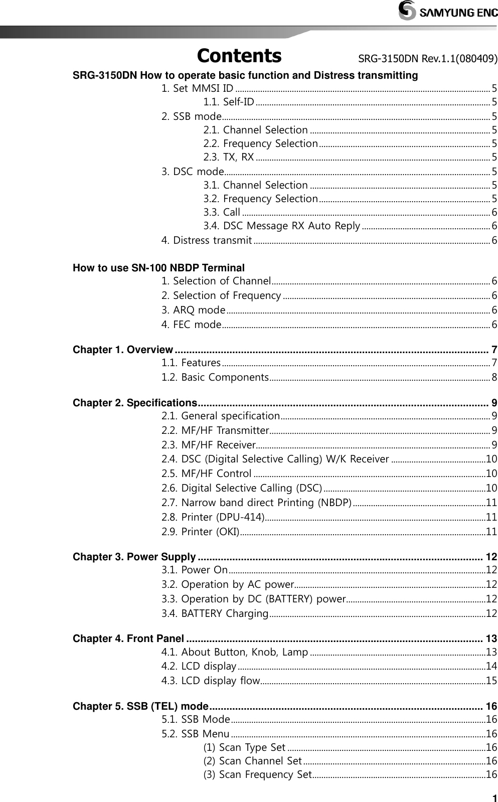
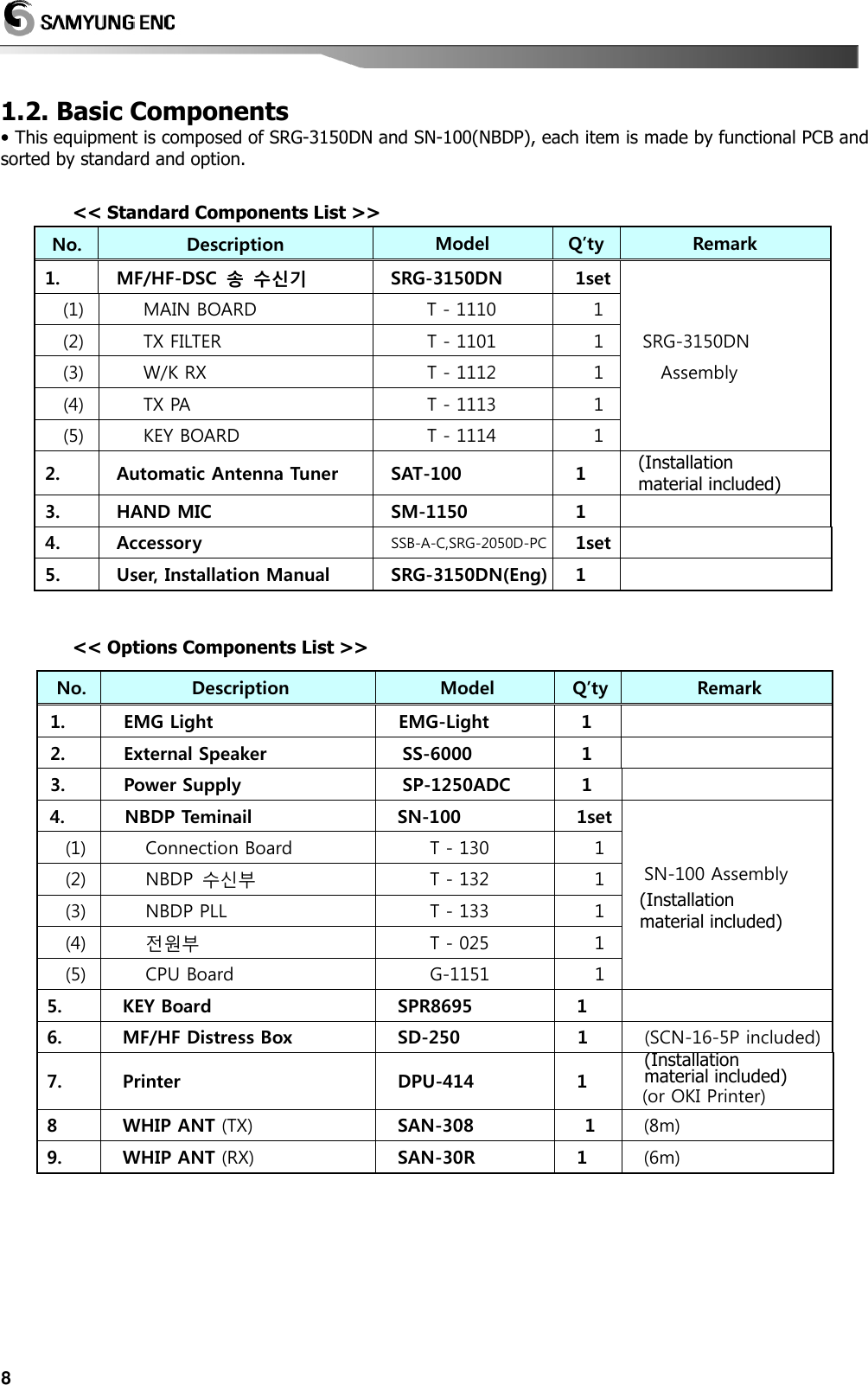
![5SRG-3150DN How to operate basic function and Distress transmitting 1. Set MMSI ID (Maritime Mobile Service Identity) • Press button and ON, It stop at the below initial display, • Then input SELF ID or handle dial/key of the front panel to be operated regularly. < Initial Screen > 1.1. Self-ID • [DSC] mode / '9. SYSTEM SET' / '1.Self ID set' Ex) Input ID 111100000 : Press any key on the initial screen Press to go to [DSC] mode twice Press( )and then go out to 'Main Menu'. (Indicated MMSI Number in the right side on the bottom) 2. SSB mode 2.1. Channel Selection • Press to go to [SSB] mode select to the channel by dial [CH] [ Ref. ] ☞ Press twice () and select to [CH]input channel with [No. button] and then press. 2.2. Frequency Selection 1)Press twice( )and select to [TX] Input frequency by [No. button] press . 2) Press twice ( )and select to [RX] Input frequency by [No. button] press . [ Ref. ] ☞☞☞☞ Missing frequency range, Cannot be input with alarm sound. 2.3. TX, RX 1) TX • Can use it after inputting to the frequency TX/RX that want to communicate. • Press to go to [SSB] mode input the frequency that want to communicate Press [Mike switch(PTT)] and communicate. [ Ref. ] ☞ Don’t have a ATU Tunning date valor of the first channel, ATU Tuning run automatically to the emergency TX(2,182 / 2,1875 / 4,2075 / 6,312 / 8,4145 / 12,477 / 16,8045 kHz). 2) Received gain adjustment • Be easy to hear on condition of low noise as down GAIN and up VOLUME. 3. DSC mode 3.1. Channel Selection • Press to go to [DSC] mode select to the channel by dial [CH] [ Ref. ] ☞ Press twice () and select to the channel [CH] and input the wanted channel by[Number]and then press . 3.2. Frequency Selection • Press twice ( ) and select [TX] Input the wanted frequency by [No. button] press . [ Ref. ] ☞ Missing frequency range, Cannot be input with alarm sound.](https://usermanual.wiki/SAMYUNG-ENC/SRG-3150DN/User-Guide-938933-Page-6.png)
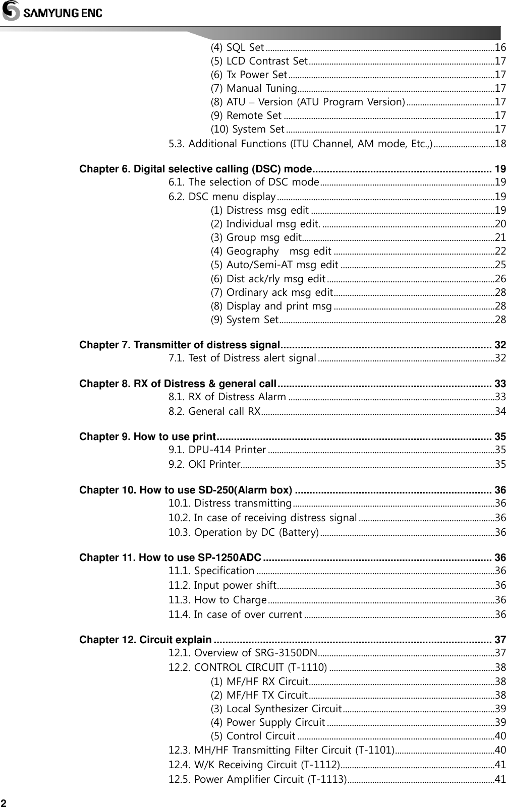
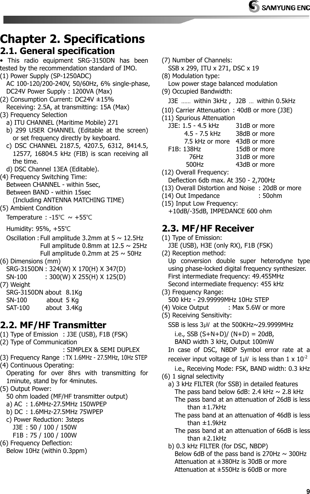
![6How to use SN-100 NBDP Terminal 3.3. Call • Press to go to [DSC] mode select to the channel by dial [CH] 3.4. DSC Message RX Auto Reply • When receive DSC message and Auto ACK on, can work automatic answer. • When receive DSC but Auto ACK off and then don’t work automatic answer. (1) How to set [DSC] mode press / ‘9.SYSTEM SET’ / ‘0.Etc Set’ / ‘4.Auto Ack’ and finished setting. 4. Distress transmit 4.1. Transmit signal(DISTRESS) by Emergency Transmitter KEY (1) Hold on 3 seconds [DISTRESS] and then transmit signal. (2) If you don’t have any reply, flicker the red[DISTS]display as follow on screen and transmit channel from 1 to 6 after 4 minutes(3min.and 30sec ~ 4min.40sec.). (3) Press and then stop to transmit. 1. Selection of Channel 1.1. Change [CH] on screen Select wanted channel by [No. button] and press [Enter] 1.2. Press [F6] Input the wanted channel by [No. button] Press [Enter] 2. Selection of Frequency 2.1. TX • Press[F7] input the wanted communicate frequency by [Number] press[Enter] 2.2. RX • Press[F8] input the wanted communicate frequency [Number] press[Enter] 3. ARQ mode • Hold [F2], Select [ARQ] You can access to one by ARQ MODE. 4. FEC mode • Hold [F2], Select [FEC] You can access to one by FEC MODE.](https://usermanual.wiki/SAMYUNG-ENC/SRG-3150DN/User-Guide-938933-Page-7.png)
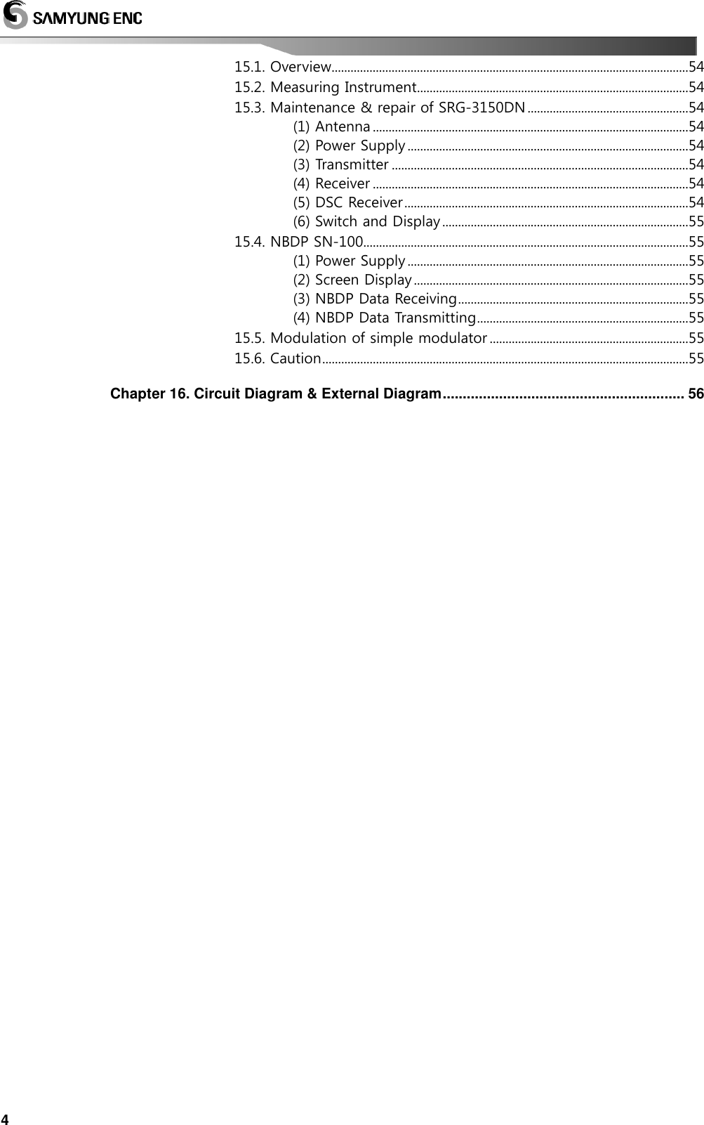
![12 Chapter 3. Power Supply 3.1. Power On (1) AC power plug put in plug receptacle, connect the battery with rear socket. (2) Check the indication of light on: AC IN, DC IN, and DC OUT of front panel. (3) Connect cables of SRG-3150DN. (4) Switch AC and DC power on. (5) Push the button. 3.2. Operation by AC power • When it comes to supply AC power to the main unit, it works with AC power automatically. W/K LED displays the condition that 6 scanning frequency is working on DSC WKR of the transceiver. (Refer to "Operation of Distress Acknowledge Signal" for operation instructions, If DSC distress or alarm call rings.) 3.3. Operation by DC (BATTERY) power • When AC power is disconnected, the SRG-3150DN switches to DC operation and [DC] LED on MF/HF control panel will light up automatically. When it is transmitted to DSC, AC signal will be changed to DC on upside of transceiver LCD display. Moreover, changing to DC mode will be displayed on downside of that. And receiving output is converted to LOW. 3.4. BATTERY Charging • When connected to AC power, except of switch on of transmitter power supply AMP power, the battery is automatically charged, a low current is supplied to maintain the rated battery voltage. The charge mode indicator between automatic and normal is by the charge switch on the system cabinet. (1) AUTO MODE: When the battery is out, charged automatically, Full time charged is set general mode. (2) NORMAL MODE: It is charged battery, regardless battery is status. To use battery longer, it is required to maintain properly for battery. Maintaining battery according to the instruction manual. (3) OFF MODE: Set the middle of switch between AUTO & NORMAL.](https://usermanual.wiki/SAMYUNG-ENC/SRG-3150DN/User-Guide-938933-Page-13.png)
![13Chapter 4. Front Panel 4.1. About Button, Knob, Lamp < SRG-3150DN Main Unit > ①. KEY Panel ②. Front Panel(LCD) - Mode / Frequency / Channel / Other function. ③. Internal Speaker ④. MIC connection jack - Connect MIC provided. ⑤. Articulation - Adjusting received signal clearly. ⑥. Gain - Adjusting Gain of Receiver. ⑦. Volume - Adjusting volume of speaker. ⑧. Channel - Adjusting channel and frequency up/down. (1) : Power ON / OFF in main unit. (2) : Hold pressing 3sec, Transmitting Distress signal. (3) : Transmitting frequency/channel & message edited by DSC mode or Stop alarm sound, Stop distress and call display also. (4) : Auto acknowledge for the received messages ON/OFF in DSC mode. (5) : Selecting main menu. (6) : Hold this key and extend functions with random keys. : Selecting "CH" "TX" "RX" in Order. (Be available to select Channel and TX/RX Frequency) : Select ATT in order. (Display LCD left-bottom) (The part of received diminution can select 3 levels) : ON/OFF internal test tone Signal at 1.4 KHz. : ON/OFF Scan function. (Display LCD on top) (Scan function of channel or frequency can be started and finished) : ON/OFF Speaker. (Display LCD on top) : Select printer function. (Can be printed to channel and message that received frequency) : ON/OFF N.B. (Display LCD left-bottom) [Ref.] ☞ when it is receiving H3E, Noise Blanker removes noise out of it. (Noise Blanker: It works to block high level of impulse of short duration as a device to cut off one stage from middle frequency of receiver.)](https://usermanual.wiki/SAMYUNG-ENC/SRG-3150DN/User-Guide-938933-Page-14.png)
![14 : ON/OFF AGC. (Display LCD left-bottom) Adjust automatically gain that bundle of amplification of receiver. (Auto Gain Control: It means that system maintain to regardless of changing of strength that input signal by the book of receiver’s power. As is higher signaling that incoming to system, diminution degree of gain is increasing, in conclusion low signal much more amplifier than high signal). : ON/OFF SQL. (Display LCD left-bottom) Delete to noise that occurred on standby receiving according to signal level. (*Squelch: mute the equipment and delete to harassing background noise and unwanted signal automatic control to the function of receiver or amplifier exception of incoming signal exceed to a set point) : By check mode, RX set displays RX signal(RxG), Voltage(24V)(VOLT), TX set displays PA currency(Ic), Antenna currency(ANT), standing wave ratio(SWR). : Adjust dimmer 5steps in front panel. : Switch AM receiving mode. : Operating matching channel before input frequency. [[[[▲▲▲▲]or[]or[]or[]or[▼▼▼▼]]]] : : : : Change of TX Frequency take turns HIGH / LOW / MID. (7) : this button is for selecting to item of selection on menu mode and for cursor moving on the display. (8) ~ : be useful to input the number. (9) : Adjust LCD back light (internal) by 4steps. (Holding [FUNC] and press [DIM], Adjust by 5steps.) (10) (10) (10) (10) : Switch SSB & DSC mode. (Holing [FUNC] and press [MODE], Switch AM mode.) [Ref.] ☞ SSB (J3E): use to voice communication DSC (F1B): use to digital selective calling communication (11) : Matching with user's antenna then push this button. (Press [FUNC] and hold with [ATU] for 2sec, Matching all channel.) (12) : Cancel set or return precious menu. (13) : Execute selecting, input, and extend...etc at the menu. (14) LED Display [DISTS]: When receive a Distress signal by W/K receiver or transmit a Distress alarm signal, be flickered LED indicator. [OTHER]: when receive DSC without DISTRESS signal, be flickered Green LED Indicator. [TX] : LED on, transmitting [W/K]: LED display …… LED on W/K receiver is operating. (Always Working) 4.2. LCD display The following information is displayed in general. (1) Communication Mode (SSB, DSC, AM (only RX)), Speaker, Acknowledge, Scan, TX power, Time (UTC GPS being connected) (2) W/K receiving channel, TX/RX frequency & channel. (3) Attenuator (ATT), Noise Blanker (N.B), AGC, Squelch. (4) RX signal level, Voltage/Currency (I-c) / (ANT-c)/ Standing-wave ratio (Select [F] + [0]), Date, time (Display UTC, if GPS receiver connected) (5) Location mark “MAN”: Manual Input “GPS”: GPS location (GPS connected) MMSI (Maritime Mobile Service Identity) ID (6) Display according to the key input. (7) Display Description A) : Display communication mode in use. b) :, ON/OFF Speaker ON - Display OFF- Display c) ACK : Display if it selected an automatic acknowledge in DSC mode. d) SCN : Press to start "SCAN" and press , and then SCAN is finished.](https://usermanual.wiki/SAMYUNG-ENC/SRG-3150DN/User-Guide-938933-Page-15.png)
![16 Chapter 5. SSB (TEL) mode 5.1. SSB Mode Press button on front panel, and then go to SSB mode. 5.2. SSB Menu On SSB Mode when press display to Menu screen as follow. . (1) Scan Type Set a) Decision scanning channel or frequency. 1. Scan Type is selected. Select, switching [CH]/ [Freq] in rotation Return to Main Display. B) , scan to select SACN Type. [Ref.] ☞ Scan type is [CH], scan channel. Scan type is [Freq], scan frequency. (2) Scan Channel Set a) Fix setting value in case of scanning channel. 2. Scan Ch. Set is selected. The below box shows. Start End Speed : : : 1 299 0 [▲][▼] Move, and select to wanted function, Selected. [Number button] Input the value. Set up. Press to back to main screen. [Ref.] ☞ [Start] : Set Start channel. [End] : Set Last channel. [Speed] : Set speed of scan channel (0~9, 0: Fastest, 9: Slowest) (3) Scan Frequency Set a) Set value in case of scanning Frequency. 3. Scan Freq. Set is selected. The below box shows. Start End Speed Step : : : : 500.00 kHz 29,999,99kHz 0 0.1 kHz [▲][▼] Move, and select to wanted function, Selected. [Number Button] Input the value. Set up. Press to back to main screen. [Ref.] ☞ [Start] : Set Start Frequency. [End] : Set Last Frequency. [Speed]: Set speed of scan Frequency. [Step] : Set step of scan Frequency. (100HZ/step) ☞ “10.0”at 10kHz step. (4) SQL Set a) On standby, if set setting value of SSB particular sound clearance highly, cannot receive slight signal. 4. SQL Set is selected. The below box shows. SQL Sense SQL Delay ::10 5 Set range : 1 ~ 20 Set range : 1 ~ 20 [▲][▼] Move, and select to wanted function, Selected. [Number button] Input the value. Set up. Press to back to main screen. [Ref.] ☞ [SQL Sense]: Set sensibility of SQL. [SQL Delay]: Set delay time of SQL circuit.](https://usermanual.wiki/SAMYUNG-ENC/SRG-3150DN/User-Guide-938933-Page-17.png)
![17 (5) LCD Contrast Set 5. LCD Contrast is selected. Press to change the LCD brightness From [1] ~ [5] step. (Higher value and more thicker) (6) Tx Power Set a) Adjust TX power. 6.Tx Power is selected. Select HIGH / MID / LOW b) If Tx Power HIGH, Display "HIGH", SRG-3150DN(J3E:150W, FIB:100W) MID, display "MID", SRG-3150DN(J3E:100W, F1B:100W) LOW, display "LOW". SRG-3150DN(J3E:50W, F1B:75W) (7) Manual Tuning a) ATU tuning by manual. 7.Manual Tuning is selected. The below box shows. [◀][▶] Select the point which it is to be adjusted by[◀][▶] [▲][▼] Adjust it’s value by [▲][▼] Selected. [Ref.] ☞ press , the value adjusted is input and return main menu. ☞ On manual tuning, TX power has not changed while switching frequency. (8) ATU – Version (ATU Program Version) 8. ATU---Version is selected. Selected. [Ref.] ☞ if ATU DATA cable has any trouble, Display "Error.” (9) Remote Set a) Set remote operating. 9. Remote OFF is selected. Press, can be changed 9.Remote ON, Display "REM" on the main screen. b) Press and then change to remote off. (10) System Set a) Select system’s value. 0. System Set is selected. The below box shows. ① [1.Tuning Clear]: Clear all the memory tuned. 1. Tuning Clear is selected. The below box shows. [▼] Move to Yes Reboot system. ② [2.SSB-CH Clear]: Delete channel data and set channel. 2. SSB-CH Clear is selected. The below box shows. [▼] Move to Yes Reboot system. ③ [3.Data-Set]: Set data in system. In external GPS Data input, UTC (Universal Time Coordinated) is displayed. ④ [4.Time-Set]: Set time in system. In external GPS Data input, UTC (Universal Time Coordinated) is displayed. ⑤ [5.Key Tone] 5. Key Tone is selected. Press, can be changed On/Off. TX Power : Tune ▼ 0.0 uH OFF OFF 0 pF 0 pF OFF](https://usermanual.wiki/SAMYUNG-ENC/SRG-3150DN/User-Guide-938933-Page-18.png)
![18 ⑥ [6.ADC Value]: RXG in first display – Show selecting ON/OFF. 6. ADC Value is selected. Press, and then can select IC, ANT, SWR, VOLT. [Ref.] ☞ RxG : Rx Signal Level (On setting IC, ANT, SWR, displayed on receiving) IC : End Current, ANT : Antenna Current SWR : Standing Wave Ratio VOLT : it means electricity, voltage and In case of setting IC, ANT and SWR, display reference to transmitting. ⑦ [7.Auto Tune] : Matching all channels automatically. 7. Auto Tune is selected. The below box shows. Freq Tune : : 2,032.0kHz Tuning - - - ⑧ [8.Self Test]: Self test function. 8. Self Test is selected. The below box shows. Version Receiver Watch-R Exciter Tuner : : : : : 2.0 good good good good ⑨ [9.Key Test]: Test button the front screen. 9. Key Test is selected. When press selected button and then display title that selected button on the screen. 5.3. Additional Functions (ITU Channel, AM mode, Etc.,) (1) ITU Channel [CH401 - CH2510], it can be selected by [CH] and [Number] on SSB Mode, if it is within reference to range channel, it can be switching channel by dial or button[up/down] of Hand-MIC. (2) Press , it switches [AM] (H3E) mode, use , it switches another mode [SSB or DSC]. [Ref.] ☞ there’s no TX display at the [AM] (only RX), AGC is set automatically. (3) DSC Channel (CH300 ~ CH399), DSC message appears, goes to mode and edit and change DSC channel by front knob, hand MIC up/down [Ref.] ☞ DSC mode / MENU > 2.Individual Msg Edit / can be edited in DSC Message by [▲] [▼]. (4) It can be moved by cursor on menu mode by [CH] dial. (5) If you want to stop on receiving [DISTS] & [OTHER] press .](https://usermanual.wiki/SAMYUNG-ENC/SRG-3150DN/User-Guide-938933-Page-19.png)
![19 Chapter 6. Digital selective calling (DSC) mode 6.1. The selection of DSC mode Set DSC Mode by on the front Panel as follow. a) CH1~CH6: In case of emergency only. Not possible to use in a normal condition. b) CH7~CH19: Normal can be used by users and pressing [SCAN] key, it can scan only in specified data location within CH7~CH19 channel. 6.2. DSC menu display Press on the initial screen of the DSC mode, the sub menu screen is set as follow. (1) Distress msg edit a) In case of calling distress. 1.Distress msg edit is selected. The below box shows. CH = 300 CH = 301 CH = 302 …… CH = 399 : : : : (NO DATA) (NO DATA) (NO DATA) …… (NO DATA) [Ref.] ☞ [▲] [▼] : Moving up and down with 1 step channel. [◀][▶] : Moving up and down with 10 step channels. [▲][▼][◀][▶] Select Channel that format is Distress Press, display can edit msg. on the screen. (Or can be edited what you want.) ① [FORMAT]: A kind of calling. Distress : Distress calling(fixed) ② [NATURE]: The type of distress. [▲][▼] Move to NATURE The below box shows. Fire, Explosion Flooding Collision Grounding Listing Sinking Adrift Undesignated Abandon ship Piracy/Attack Man Overboard [▲][▼] Go to the menu you want. Selected. ③ [POSITION]: Position of distress. (Auto-set in a connection with GPS) [▲][▼] Move to POSITION The below box shows. N _ _ , _ _ , _ _ _ _ / E _ _ _ , _ _ , _ _ _ _ North latitude(00.00.0000~90.00.0000) east longitude(000.00.0000~180.00.0000) S _ _ , _ _ , _ _ _ _ / W _ _ _ , _ _ , _ _ _ _ South latitude(00.00.0000~90.00.0000) west longitude(000.00.0000~180.00.0000) [Number button] Input the value. Set up. [Ref.] ☞ Press [▲] [▼] to change [N_-- E --_] / [S -- W_--] / [S – E --] / [N -- W_--] in turns ☞ If the value is beyond the value range, the set up can not be done.](https://usermanual.wiki/SAMYUNG-ENC/SRG-3150DN/User-Guide-938933-Page-20.png)
![20④ [DIST-UTC]: Set time of distress. [▲][▼] Move to DIST-UTC The below box shows. - - : - - - : Time of Distress(00:00 - 23:59) [Number. button] Input the time. Selected. [Ref.] ☞ Set automatically in connection with GPS. ⑤ [TEL CMD]: Set Telecomm and. [▲][▼] Move to TEL-CMD Press to change [J3E TP] / [FIB/J2B T]. ⑥ [EOS]: Completion of DSC message. (EOS=End of Sequence) EOS – Set automatically. (fixed) shown [……File Saved……] and be saved... b) After setting items press and then transmit DISTRESS signal as Frequency that before edition on DSC main screen. (2) Individual msg edit. a) Used in an individual call or coast station call. 2. Individual mag edit is selected. The below box shows. CH = 300 CH = 301 CH = 302 …… CH = 399 : : : : (NO DATA) (NO DATA) (NO DATA) …… (NO DATA) [Ref.] ☞ [▲] [▼] : Moving up and down with 1 step channel. [◀][▶] : Moving up and down with 10 step channels. [▲][▼][◀][▶] The channel is selected. The below box shows. ① [TX-Freq]: Set TX frequency. [▲][▼] Move to TX-Freq The below box shows. 01 02 03 04 05 06 19 : : : : : : 2,187.50 4,207.50 6,312.00 8,414.50 12,577.00 16,804.50 8,414.50 [Ref.] ☞ MENU>9.SYSTEM SET>0.Etc. Set>3.Default Channel possible to select default TX frequency. [▲][▼] The frequency is selected. Selected. [Ref.] ☞ Indicate the frequencies which is memorized by user in DSC mode CH7~19. ② [FORMAT]: A kind of calling. Individual : an individual calling(fixed) ③ [CATEGORY]: Purpose of calling. [▲][▼] Move to CATEGORY The below box shows. Routine Safety Urgency : [▲][▼] Go to the menu you want. Selected. ④ [PARTY ID]: Input the ID of counter party. [▲][▼] Move to PARTY_ID Selected. [Number. button] Input ID. Set up. ⑤ [TEL CMD1]: Set Telecommand1. [▲][▼] Move to TEL CMD1 The below box shows. [▲][▼] Go to the menu you want. Selected. ⑥ [TEL CMD2]: Fix “No information”](https://usermanual.wiki/SAMYUNG-ENC/SRG-3150DN/User-Guide-938933-Page-21.png)
![21⑦ [WORK FRQ]: Operational frequency. [▲][▼] Move to WORK FRQ Selected. [Number. button] Input TX frequency. Set up. [Number. button] Input RX frequency. Set up. ⑧ [EOS]: Completion of DSC message. (EOS=End of Sequence) ACK RQ : Auto-set.(Fixed) [Ref.] ☞ ACK RQ: Function to request other’s response. (ACK=Acknowledge=Auto response) b) Function Keys ① After inputting data press and it is saved. ②select [PARTY-ID]press and registered ID list shows select by [▲][▼] [Ref.] ☞How to register ID: MENU>9.SYSTEM SET>5.ID/FR/TEL Set>1.ID Edit and register. ③ Select[WORK FRQ]press and registered frequency list shows select by [▲][▼] [Ref.] ☞ How to register frequency that communicate with voice: MENU>9.SYSTEM SET>5.ID/FR/TEL Set>3.Work Frequency Edit and register. ④ select [WORK FRQ] press to change [WORK FRQ] / [POSITION]. Select [POSITION] by Input by [No. button] c) After setting items, press and “individual call” signal transmits. d) When ACK response signal is received, communication can be possible with the voice communication frequency. (3) Group msg edit a) Call specified ships as such a same group or company simultaneously. 3. Group msg edit is selected. The below box shows. CH = 300 CH = 301 CH = 302 …… CH = 399 : : : : (NO DATA) (NO DATA) (NO DATA) …… (NO DATA) [▲][▼][◀][▶] The channel is selected. The below box shows. ① [TX-Freq]: Set TX frequency. [▲][▼] Move to TX-Freq The below box shows. 01 02 03 04 05 06 19 : : : : : : : 2,187.50 4,207.50 6,312.00 8,414.50 12,577.00 16,804.50 8,414.50 [▲][▼] The frequency is selected. Selected. [Ref.] ☞ Indicate the frequencies which is memorized by user in DSC mode CH7~19. ② [FORMAT]: A kind of calling. Group : Group calling(fixed) ③ [CATEGORY]: Purpose of calling. Routine : use general (fixed)](https://usermanual.wiki/SAMYUNG-ENC/SRG-3150DN/User-Guide-938933-Page-22.png)
![22④ [PARTY ID] : Input the ID of counter party. [▲][▼] Move to PARTY_ID Selected. [Number. button] Input ID. Set up. ⑤ [TEL CMD1]: Set Telecommand1. [▲][▼] Move to TEL CMD1 Press to change [J3E TP] / [FIB/J2B TTY-FFC]. ⑥ [TEL CMD2]: Fix“No information” ⑦ [WORK FRQ]: Operational frequency. [▲][▼] Move to WORK FRQ Selected. [Number. button] Input TX frequency. Set up. [Number. button] Input RX frequency. Set up. ⑧ [EOS]: Completion of DSC message. (EOS=End of Sequence) EOS: Auto - set. (fixed) b) Function Keys ① After inputting data press and it is saved. ②select [PARTY-ID]press and registered ID list shows select by [▲][▼] [Ref.] ☞How to register ID: MENU>9.SYSTEM SET>5.ID/FR/TEL Set>1.ID Edit and register. ③ Select[WORK FRQ]press and registered frequency list shows select by [▲][▼] [Ref.] ☞ How to register frequency that communicate with voice: MENU>9.SYSTEM SET>5.ID/FR/TEL Set>3.Work Frequency Edit and register. c) After setting items, press and “group call” signal transmits. d) When ACK response signal is received, communication can be possible with the voice communication frequency. (4) Geography msg edit a) calling all ships by coast station call. Use for communicating with all ships about safety and others by coast station call. When coast station call, will be waited automatically all ships as set voice communication frequency. b) calling all ships by base of ships. It’s no use generally. Use for emergency or sending important information. 4.Geography msg edit is selected. The below box shows. CH = 300 CH = 301 CH = 302 …… CH = 399 : : : : (NO DATA) (NO DATA) (NO DATA) …… (NO DATA) [▲][▼][◀][▶] The channel is selected. The below box shows. ① [TX-Freq]: Set TX frequency. [▲][▼] Move to TX-Freq The below box shows. 01 02 03 04 05 06 19 : : : : : : 2,187.50 4,207.50 6,312.00 8,414.50 12,577.00 16,804.50 8,414.50 [▲][▼] The frequency is selected. Selected.](https://usermanual.wiki/SAMYUNG-ENC/SRG-3150DN/User-Guide-938933-Page-23.png)
![23[Ref.] ☞ Indicate the frequencies which is memorized by user in DSC mode CH7~19. ② [FORMAT]: A kind of calling. Geography : local calling(fixed) ③ [CATEGORY]: Purpose of calling. [▲][▼] Move to CATEGORY Press to change [Safety] / [Urgency]. ④ [PARTY AD]: reference to 24page. ⑤ [TEL CMD1]: Set Telecommand1. [▲][▼] Move to TEL CMD1 Press to change [J3E TP] / [FIB/J2B TTY-FFC]. ⑥ [TEL CMD2]: Set Telecommand2. In case of setting [Safety], fix“No information”in [CATEGORY]. In case of setting [Urgency] in [CATEGORY]. (☞ MENU>9.SYSTEM SET>0.Etc. Set> 9.Medi-Trans. Set and select on) [▲][▼] Move to TEL CMD2 The below box shows. [▲][▼] Go to the menu you want. Selected. ⑦ [WORK FRQ]: Operational frequency. [▲][▼] Move to WORK FRQ Selected. [Number. button] input TX frequency. Set up. [Number. button] input RX frequency. Set up. ⑧ [EOS]: Completion of DSC message. EOS : Auto - set.(fixed) c) Function Keys ① After inputting data press and it is saved. ②select [PARTY-ID]press and registered ID list shows select by [▲][▼] [Ref.] ☞How to register ID: MENU>9.SYSTEM SET>5.ID/FR/TEL Set>1.ID Edit and register. ③ Select[WORK FRQ]press and registered frequency list shows select by [▲][▼] [Ref.] ☞ How to register frequency that communicate with voice: MENU>9.SYSTEM SET>5.ID/FR/TEL Set>3.Work Frequency Edit and register. c) After setting items, press and “Geography call” signal transmits. d) When ACK response signal is received, communication can be possible with the voice communication frequency.](https://usermanual.wiki/SAMYUNG-ENC/SRG-3150DN/User-Guide-938933-Page-24.png)
![24 ④ [PARTY AD]: Input location data [▲][▼] Move to PARTY_AD Selected. N _ _ : North latitude (00 - 90) (φ ) S _ _ : South latitude (00 - 90) (φ ) E _ _ : East longitude (000 - 180) (λ ) W _ _ _ : West longitude (000 - 180) (λ ) DA _ _ : Latitude range (Offset Value) (汁φ) Do _ _ : Longitude range(Offset Value) (汁λ) [Number. button] Input the value. Set up. [Ref.] ☞ every press [▲] [▼] N_ _ E_ _ / S_ _ W_ _ / S_ _ E_ _ / N_ _ W_ _be switched in turns. [Ref.] ☞ φ = Latitude λ = Longitude Δφ = Latitude Range Δλ = Longitude Range](https://usermanual.wiki/SAMYUNG-ENC/SRG-3150DN/User-Guide-938933-Page-25.png)
![25 (5) Auto/Semi-AT msg edit a) Use for communicating connected with telephone. 5.Auto/Semi-AT mag edit is selected. The below box shows. CH = 300 CH = 301 CH = 302 …… CH = 399 : : : : (NO DATA) (NO DATA) (NO DATA) …… (NO DATA) [▲][▼][◀][▶] The channel is selected. The below box shows. ① [TX-Freq]: Set TX frequency. [▲][▼] Move to TX-Freq The below box shows. 01 02 03 04 05 06 19 : : : : : : : 2,187.50 4,207.50 6,312.00 8,414.50 12,577.00 16,804.50 8,414.50 [▲][▼] The frequency is selected. Selected. [Ref.] ☞ Indicate the frequencies which is memorized by user in DSC mode CH7~19. ② [FORMAT]: A kind of calling. AT/semi-AT : AT/semi-AT Calling(fixed) ③ [CATEGORY]: Purpose of calling. Routine : use generally (fixed) ④ [PARTY ID]: Input ID. [▲][▼] Move to PARTY_ID Press. [Number. button] Input ID. Set up. ⑤ [TEL CMD1]: Set Telecommand1. [▲][▼] Move to TEL CMD1 The below box shows. [▲][▼] Go to the menu you want. Selected. ⑥ [TEL CMD2]: fix “No information”. ⑦ [WORK FRQ]: Operational frequency. [▲][▼] Move to WORK FRQ Selected. [Number. button] input TX frequency. Set up. [Number. button] input RX frequency. Set up. ⑧ [TEL NO.]: Input telephone number. [▲][▼] Move to TEL NO. Selected. [Number. button] Input telephone number. Set up. ⑨ [EOS]: Completion of DSC message. ACK RQ : Auto-set.(fixed) b) Function keys ① After inputting data press and it is saved. ②select [PARTY-ID]press and registered ID list shows select by [▲][▼] [Ref.] ☞How to register ID: MENU>9.SYSTEM SET>5.ID/FR/TEL Set>1.ID Edit and register.](https://usermanual.wiki/SAMYUNG-ENC/SRG-3150DN/User-Guide-938933-Page-26.png)
![26 ③ Select[WORK FRQ]press and registered frequency list shows select by [▲][▼] [Ref.] ☞ How to register frequency that communicate with voice: MENU>9.SYSTEM SET>5.ID/FR/TEL Set>3.Work Frequency Edit and register. ④ select [WORK FRQ] press to change [WORK FRQ] / [POSITION]. Select [POSITION] by Input by [No. button] ⑤Select [TEL NO.]press and shown registered Telephone No. List select by [▲][▼] [Ref.] ☞ How to register Telephone No: MENU> 9.SYSTEM SET>5.ID/FR/TEL Set> 3.Telephone No. Edit and register) c) After setting items, press and signal transmits. d) Coast station call by telephone with calling data, connect the signal and send ACK signal to ship and then will be communicated as switching fixed voice communication frequency. (6) Dist ack/rly msg edit a) After inputting the info. , use this menu to respond to distress signal and manual relay of the distress message. 6.Dist ack/rly msg edit is selected. The below box shows. b) It is memory channel using from 400 to 499 as right on the top. [Ref.] ☞ [▲] [▼] : Moving up and down with 1 step channel. [◀][▶] : Moving up and down with 10 step channels. c) When received recently distress signal from other ship, can check the message. Press , input ID press and then transmit to Distress signal. d) Press , shown new relay message on screen and will be editable. When can not send distress signal, edit and press and then can be transmitted. ① [TX-Freq]: Set TX frequency. [▲][▼] Move to TX-Freq The below box shows. 01 02 03 04 05 06 19 : : : : : : : 2,187.50 4,207.50 6,312.00 8,414.50 12,577.00 16,804.50 8,414.50 [▲][▼] The frequency is selected. Selected. [Ref.] ☞ Indicate the frequencies which is memorized by user in DSC mode CH7~19. ② [FORMAT]: A kind of calling. [▲][▼] Move to FORMAT Press to change [Geography] / [Individual]. ③ [CATEGORY]: Purpose of calling. Distress : Distress calling(fixed)](https://usermanual.wiki/SAMYUNG-ENC/SRG-3150DN/User-Guide-938933-Page-27.png)
![27 ④ [PARTY ID] : Input the ID of counter party. In case of selecting [Individual] in [FORMAT], input ID [▲][▼] Move to PARTY_ID Selected. [Number. button] Input ID. Set up. Select [FORMAT] In case of [Geography], shown [PARTY-AD], input specific area. [▲][▼] Move to PARTY_AD Selected. [Number. button] Input ID. Set up. [Ref.] ☞ MENU>4.Geography msg edit/ PARTY AD and register. ⑤ [TEL CMD]: fix“Distress Relay” [Ref.] ☞ Distress Relay: in case of relaying broadcast cause the distance is far from coast station. ⑥ [DIST ID]: Input the ID of the vessel in distress. [▲][▼] Move to DIST ID Selected. [Number. button] Input ID. Set up. ⑦ [NATURE]: The type of distress. [▲][▼] Move to NATURE The below box shows. Fire, Explosion Flooding Collision Grounding Listing Sinking Adrift Undesignated Abandon ship Piracy/Attack Man Overboard [▲][▼] Go to the menu you want. Selected. ⑧ [POSITION]: Input the Position of the vessel in distress. [▲][▼] Move to POSITION The below box shows. N _ _ , _ _ , _ _ _ _ / E _ _ _ , _ _ , _ _ _ _ North latitude(00.00.0000~90.00.0000) east longitude(000.00.0000~180.00.0000) S _ _ , _ _ , _ _ _ _ / W _ _ _ , _ _ , _ _ _ _ South latitude(00.00.0000~90.00.0000) west longitude(000.00.0000~180.00.0000) [Number button] Input the value. Set up. [Ref.] ☞ Press [▲] [▼] to change [N_-- E --_] / [S -- W_--] / [S – E --] / [N -- W_--] in turns ☞ If the value is beyond the value range, the set up can not be done. ⑨ [DIST-UTC]: Input the time of distress. [▲][▼] Move to DIST-UTC The below box shows. - - : - - - : Time of Distress(00:00 - 23:59) [Number. button] Input the time. Selected. [Ref.] ☞ Set automatically in connection with GPS. ⑩ [TEL CMD]: Set Telecommand. [▲][▼] Move to TEL CMD Press to change [J3E TP] / [FIB/J2B TTY-FFC]. ⑪ [EOS]: Completion of DSC message. (EOS= End of Sequence) ACK RQ: Auto - set. (fixed) e) After setting items, press and signal transmits. f) When other ship or coast station send ACK answer, ship that transmitted distress be going to receive.](https://usermanual.wiki/SAMYUNG-ENC/SRG-3150DN/User-Guide-938933-Page-28.png)
![28 (7) Ordinary ack msg edit a) In case of common answer call. 7. Ordinary ack msg edit is selected. The below box shows. b) Memory channel is from 500 to 599 and it shows on the right top of the box. You can see the general info. Except distress signal. [Ref.] ☞ [▲] [▼]: Moving up and down with 1 step channel. [◀][▶]: Moving up and down with 10 step channels. c) In this menu press and can be answered. (8) Display and print msg a) In checking the written messages or auto printing. 8. Display and print msg is selected. The below box shows. b) Channels are 300 to 399, can be confirmed on screen. [Ref.] ☞ [▲] [▼]: Moving up and down with 1 step channel. c) If this mode is selected with the printer connected, printing of the message starts automatically. (9) System Set a) in case of setting the value of SYSTEM. 9. System Set is selected. The below box shows. ① [1.Self ID Set]: Input own ship ID. 1. Self ID Set is selected. Selected. [Number. button] Input ID. Set up. ② [2.Group-ID Set]: Input Group ID. 2. Group ID Set is selected. Selected. [Number. button] Input ID. Set up. [Ref.] ☞ it’s possible to input just 1 time because ID is proper number of the ship, so if you want to make modification, you can reach in menu by password. Distributor has a password. [Ref.] ☞ How to change ID. Press to go to [SSB] mode [ ] [ ] [ ] [ ] (Password-Contact dealers) (Set as ‘ENABLE’) (Return to main screen) [Self-ID Set] Press to go to [DSC] mode Input by [No. button] [Group-ID Set] Press to go to [DSC] mode Input by [No. button]](https://usermanual.wiki/SAMYUNG-ENC/SRG-3150DN/User-Guide-938933-Page-29.png)
![29 ③ [3.Dist TEL-CMD]: Set Telecommand. 3. Dist TEL-CMD is selected. Press to change [J3E TP] / [FIB/J2B T]. ④ [4.LAT / LON Set]: Set Lat/Lon of GPS by hand-operation. 4. LAT/LON Set is selected. The below box shows. [Number button] Input the value. Set up. ⑤ [5.ID/FR/TEL Set]: Edit ID/Auto answering ID/Operating frequency/Telephone number. [1.ID] edit 5. ID/FR/TEL Set is selected. Selected. 1. ID is selected. The below box shows. The below box shows. [Number button],][▶] Select Character, move, Select Character, move The below box shows. 0 0 0 0 0 0 0 0 0 [Number. button] Input ID. Set up. If want to return menu. Ex) How to input ID and ship’s name: “SAMYUNG”, “101010000” [▶] [▶] [▶] [▶] [▶] [▶] It is input as below [Ref.] ☞ Blank is filling with “0.” [2. Auto-ack ID] edit 5. ID/FR/TEL Set is selected. Selected. 2. Auto-ack ID is selected. , Selected. [Number. button] Input ID. Set up. [3. Work Frequency] edit 5. ID/FR/TEL Set is selected. Selected. 3. Work Frequency is selected. , Selected. [Number. button] Input TX frequency. Set up. [Number. button] Input RX frequency. Set up. [4. Telephone No.] Edit 5. ID/FR/TEL Set is selected. Selected. 4. Telephone No. is selected. , Selected. [Number. button] Input telephone number. Set up.](https://usermanual.wiki/SAMYUNG-ENC/SRG-3150DN/User-Guide-938933-Page-30.png)
![30⑥ [6.WKR Scan Set] 6. WKR Scan Set is selected. The below box shows. 2187.5 on 4207.5 on 6312.0 off 8414.5 on 12577.5 off 16804.5 off [▲][▼] The frequency is selected. Press to change [on] / [off]. [Ref.] ☞ [2187.5] and [8414.5] must be on. ⑦ [7.Data Clear]: Able to delete the user data and received data. 7. Data Clear is selected. The below box shows. 1.DSC Made-File clear 2.DSC Distress clear 3.DSC Ordinary clear 4.DSC Channel clear 5.DSC All Data clear →User DSC data →Distress data among received DSC data →Data except Distress data among Received data →Delete all data of DSC Channel →Clear all data of DSC to make an initial [▲][▼] Go to the menu you want. The below box shows. [▼] Move to Yes The data will be deleted ⑧ [8.ID printing]: Print ID. ⑨ [9.Data Transmit]: Able to select type of transmitting data and can be used in data transmitting. 9. Data Transmit is selected. The below box shows. 1.Dot Transmit 2.Mark transmit 3.Space Transmit → Send Dot signal only → Send Mark signal only → Send space signal only [Ref.] ☞ select on of them by [▼] [▲] press and then it is transmitted immediately so must be careful. ⑩ [0.Etc. Set]: Set etcetera system. 0. Etc. Set is selected. The below box shows. [1. GPS Alarm] 1. GPS Alarm is selected. Press to change [on] / [off]. [Ref.] ☞ Regardless of “on” don’t received GPS signal, display “error” on screen and sound alarm continually. [2. Scan Speed]: Adjust SCAN speed of usable DSC channel by user. The higher number it is, the slower speed (7~19Ch). 2. Scan Speed is selected. Selected. [Number. button] Input the value. Set up. [3. Default Channel]: [SIN] = If set Single MENU>2.Individual msg edit / 3.Group msg edit / 4.Use Geography msg edit. 3. Default Channel is selected. Selected. 2,187.5 4,207.5 6,312.0 8,414.5 12,577.0 16,804.5 [▲][▼] The frequency is selected. Selected. [4. Auto ACK]: Auto answer on distress calling. 4. Auto ACK is selected. Press to change [on] / [off]. [Ref.] ☞ showed “ACK” on screen, in case of setting “on.”](https://usermanual.wiki/SAMYUNG-ENC/SRG-3150DN/User-Guide-938933-Page-31.png)
![31 [5. DSC Msg Receive]: Receive DSC message. 5. DSC Msg Receive is selected. Press to change [on] / [off]. [Ref.] ☞ message receiving is not available. [6. DSC Trans. Mode]: Set DISTRESS TX channels SIN (single) or MUL (multi). 6. DSC Trans Mode is selected. Press to change [MUL] / [SIN]. [Ref.] ☞ Select [MUL], transmit 6channels in turns and select [SIN] the first channel (2,187.50 KHz) just transmit 5 times repetitively. [7. DSC Geo. Range]: Set area range Geography message transmitting. 7. DSC Geo Range is selected. Press to change [120] / [240]. / [360] / [500] / [600]. (단위는 NM) [Ref.] ☞ MENU>4.Geography msg edit on screen. In case of setting [PARTY-AD] area range, just input latitude and longitude and press and then setting value shown that are inputted of changing value of latitude range and longitude. [8. Dist-Key Test]: [DISTRESS] button Test. 8. Dist-Key Test is selected. The below box shows. Press Distress Key Press [DISTRESS] for 3 seconds and the below box shows. Press Stop Key Back to Main screen. [9. Medi-Trans. Set]: Set Medical Transport [on] / [off]. 9. Medi Trans Set is selected. Press to change [on] / [off]. [Ref.] ☞ in case of setting “on” MENU>4.Geography msg edit>TEL CMD2 and then can be set.](https://usermanual.wiki/SAMYUNG-ENC/SRG-3150DN/User-Guide-938933-Page-32.png)
![32 Chapter 7. Transmitter of distress signal 7.1. Test of Distress alert signal (1) Hold on 3 seconds [DISTRESS] in the panel, flicker DISTS] LED with alarm and after 3 seconds shown following screen, [DISTS] LED is lighted and transmit distress location, distress time, ID. •Transmit channel 1 ~ 6 as follow. 01 02 03 04 05 06 : : : : : : 2,187.5 4,207.5 6,312.0 8,414.5 12,577.0 16,804.5 (2) If don’t have a answer, flicker[DISTS] LED and shown following screen and then after 4 minutes(3min 30sec ~4min 40sec), transmit channel 1 ~ 6. [Ref.] ☞ begin in countdown “Left 04:00.” (3) If you want to stop to transmit, press . Even you press ; channel that is transmitting will be stop after finishing the transmitting. [Ref.] ☞ MENU>9.System Set>1.Self ID Set If it didn’t set and then flicker [MMSI not entered] on main screen and can’t transmit.](https://usermanual.wiki/SAMYUNG-ENC/SRG-3150DN/User-Guide-938933-Page-33.png)
![33 Chapter 8. RX of Distress & general call8.1. RX of Distress Alarm (1) Once Distress alarm is received from Distressed vessel, Red color [DISTS] LED is blinking and Alarm sounds. To stop the Alarm, press . If the CRS reply to the Distress message, the reply messages appear. (Normally within 3 min.) If the Distressed vessel receives ACK message from CRS, follow the CRS instruction. (2) Flow Chart No Yes No No Yes Check the ID, Distress position on the saved message screen. Distress Alarm RX Press button to stop the alarm. Press button and stop the alarm. Rx ACK within 3 min. from CRS. (Alarm sounds) Check the saved messages Beyond 150 nm from own ship Is the distressed vessel near own ship? In case own ship go and rescue the distress vessel, use radio telephone on the distress frequency. Check the distress vessel is near own ship? Keep listening to the distress frequency (Stand-by for the CRS instruction and listen to the distress communication until it finishes. On the DSC menu, select Distress relay. After editing, press call button to relay the distress. After relay the distress signal, wait for the reply from CRS. Red color [DISTS] LED blinks and alarm sounds](https://usermanual.wiki/SAMYUNG-ENC/SRG-3150DN/User-Guide-938933-Page-34.png)
![34 8.2. General call RX (1) In case [Auto ACK] is [on], if you receive individual call & group call, automatically, ACK reply transmits and the frequency is set to TX/RX counter party. (2) Flow Chart In case [Auto ACK] setting is [on], ACK reply is transmitted, Automatically, the frequency is shifted to voice communication frequency and then voice communication is possible. RX Individual Call In case [Auto ACK] set is [off], press button and transmit , then the frequency is shifted to voice communication frequency and the voice communication is possible. Communicate with counter party Green [OTHER] LED blinks and alarm sounds. Communication ends](https://usermanual.wiki/SAMYUNG-ENC/SRG-3150DN/User-Guide-938933-Page-35.png)
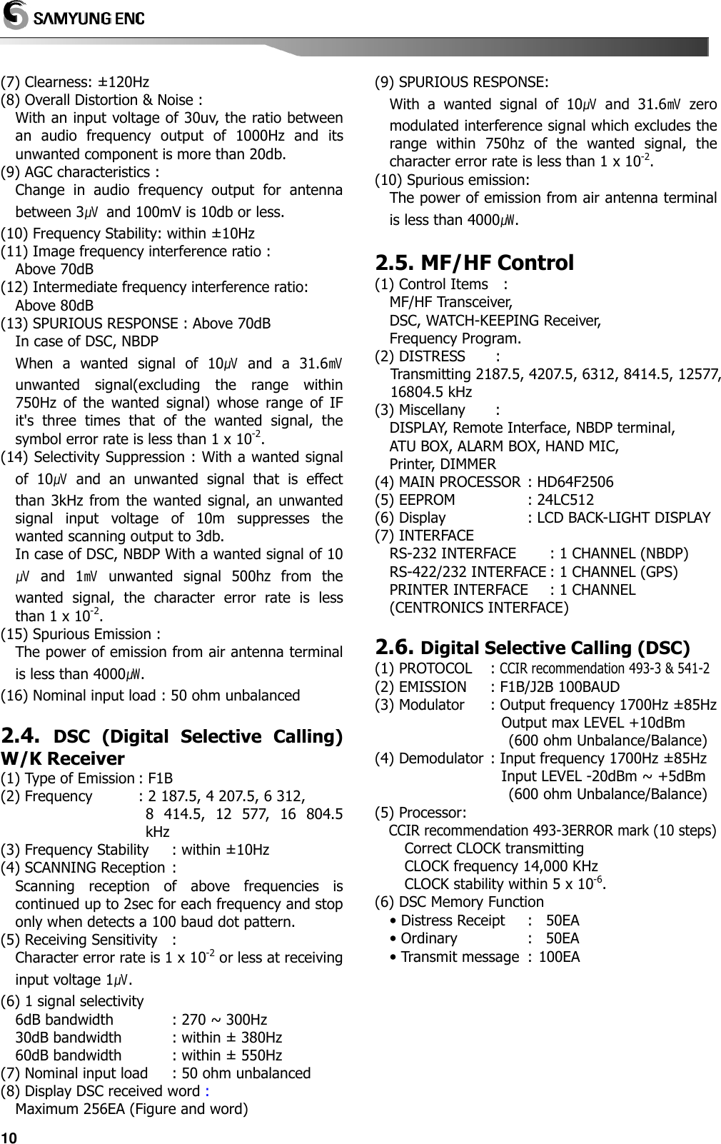
![43 Chapter 13. NBDP Terminal 13.1. NBDP Terminal Main Unit < NBDP PICTURE > ①. FRONT PANEL (LCD): CHANNEL, TX/RX FREQUENCY, RF.GAIN, CLARIFY; ATT, AGC, and FUNCTION KEYS are displayed. ②. SPEAKER : Alarm rings when it receives data or warning signal. ③. TX LED : Red light on TX LED ④. RX LED : Green light blinks while receiving data ⑤. POWER SWITCH : SN-100 Power ON/OFF 13.2. Initial Display of Telex (NBDP) mode Power on, indicate first display as followings (1) Initial screen function explanation Indicate calling channel and present channel Set transmitting frequency Set receiving frequency Indicate adjusting portion as Bar Graph Adjust the portion of RF GAIN properly using up/down with direction keys. (0~ 100steps) The button to adjust the clarity of RX. Using direction button, increase or decrease to gain the best RX. (Adjustment range: ±10Hz) Function to reduce the RX gain. This function can be adjusted in 4 steps using up/down button. OFF : 0dBm, 2 : 20 dBm 1 : 10dBm, 3 : 30 dBm Adjust TX power HIGH/MID/LOW Profit of input signal ON/OFF automatically. Volume sound is displayed on Graphic bar (0~100 levels) (2) Initial screen function button explanation [1 DIM] : Adjust the lightness of back light on LCD display. (5 LEVEL) [2 LINK] : Automatic Repeat request mode & FEC mode can be set up by [F2] button [3 COMM] : Call the registered frequency. [4 VOL-] : Volume down the speaker. [5 VOL+] : Volume up the speaker. [6 CH] : Set the frequency channel [7 TX]: TX : Set TX frequency. [8 Rx]: RX : Set RX frequency. [9 Tune] : is used when user want to do matching to antenna. [0 Menu] : Indicate Main Menu 0. [ARQ] : Communicate with Automatic Repeat Request Mode. 1. [FEC] : Communicate with 1 way Forward Error Correction. 2. [Station Edit] : Register the frequency of the other station. 3. [Station Print] : Print out the frequency of registered the other station. 4. [Macro Command] : Write Macro command. (Write short sentence in 20 words) 5. [Editor] : Edit file and save content. 6. [System set] : Use while adjusting TELEX mode condition. CH TX RX BAR GRAPH RF GAIN CLARIFY ATT TX Power AGC Vol GRAPH](https://usermanual.wiki/SAMYUNG-ENC/SRG-3150DN/User-Guide-938933-Page-44.png)
![447. [NBDP Test] : Transmitting signals of Dot, Mark, Space. Use for testing printer and NBDP TX/RX condition. 8. [LCD-off (F12) : The function of LCD off and in the case that LCD is off, if any button is pressed, LCD is on. (3) Control function in Keyboard [PgUp] : Adjust channel to next channel. But if next channel is not registered, it moves to next channel of it. [PgDn] : Adjust channel to forward channel. But, if forward channel is not registered, it moves to forward channel of it. 13.3. SettingUpTX/RX Frequency UNIT: kHz (1) Setting TX frequency a) Press [F7] button on the keyboard. b) Input the frequency with [Number button]. [Ref.] ☞ While inputting frequency if press [], [], curser will move. c) Press [Enter] button. [Ref.] ☞ Available TX Frequency range: 1.6MHz ~ 27.5MHz. (2) Setting Rx frequency a) Press [F8] button. b) Input the frequency with [Number button]. [Ref.] ☞ While inputting frequency if press [], [], curser will move. c) Press [Enter] button. [Ref.] ☞ Available RX Frequency range: 95 KHz ~ 29.99999MHz. (3) Coast Radio Station TX/RX frequency set up a) Press [F3] button, display as followings. b) Revert the other station you want to communicate using [],[],[],[] button. press [Enter] button, the following screen will show. c) Revert the channel you want to communicate using [],[],[],[] button. press [Enter] button. Set TX/RX frequency to registered freq. on channel displaying the first display of NBDP. (4) Setting TX/RX Freq. by calling channel a) Press [F6]. b) Input the channel with [Number button]. c) Press [Enter] button. 13.4. [ARQ] mode (1) Connecting with the other station by ARQ mode. Connecting by present adjusting channel. a) Press [F2] button on the keyboard and Link Menu screen shows. b) Move the cursor with []/[] button to ‘1. [ARQ]’ press [Enter], then it will be connected with other party through [ARQ] mode in present setting Channel.](https://usermanual.wiki/SAMYUNG-ENC/SRG-3150DN/User-Guide-938933-Page-45.png)
![45 (2) Connecting specific station a) Call the menu pressing [F10] to call SUB MENU key. b) Move the cursor with []/[] button to ‘0. [ARQ]’ press [Enter] and the following screen will appear. c) Revert the other station you want to communicate using [],[],[],[] button. press [Enter] button, the following screen will show. [Ref.] ☞ can be back to forward display pressing [ESC] button. d) Revert the channel you want to communicate using [],[],[],[] button. press [Enter] button. e) Call the other station with selected frequency displaying next [ARQ] mode first display. [Ref.] ☞ to stop calling, press [F8] and it will be back to Telex initial screen. f) If connected, cursor blinks on the left top of the screen. (3) Communication in ARQ mode Perform (1) or (2) and operate as below order. a) As long as you can connect with the other station in [ARQ] mode, above screen is displayed. You can keep communicating in this condition. b) After typing the message with keyboard, press [Enter] button. [Ref.] ☞ Back space - delete one character on the left. Before you press [Enter] button, transmitting is not complete. c) Usable keys in ARQ mode The usable characters: ABDCDEFGHIJKLMNOPQRSTUVWXYZ1234567890 -? ().'=/+abcdefghijklmnopqrstuvwxyz [Back space] : Delete one character on the left [Enter] : Send one line. [Left Shift] + [Space] : Convert language. (English, Russian) [Korean] is selected : [Korean] / [English] shift [English] is selected : [English] [Russian] is selected : [Russian]/[English] shift [F1] : [1 WHU] - Demand Answer back code of the other station. [F2] : [2 Hereis] - Transmit Answer back code of yourself. [F3] : [3 TMS] - Transmit the present time [F4] : [4 F.send] - Transmit the file written in edit mode. (Refer to (4) TX of file) [F5] : [5 Macro] –You can use the sentence no. Written in Macro Command (Refer to ‘(5) Macro Command RX) [F7] : [7 Over] - Convert the direction of transmitting the message. [F8] : [8 Stop] - Stop communication. [F9] : [9 VOL-] – Volume can be reduced. [F10] : [0 VOL+] – Volume can be increased.](https://usermanual.wiki/SAMYUNG-ENC/SRG-3150DN/User-Guide-938933-Page-46.png)
![46 (4) Transmitting file After performing ‘(1)’ or ‘(2)’, operate the unit as below order. a) Press Function button [F4] Move the cursor to the file you want using []/[] button Press [Enter] button and the file will be transmitted showing the file contents on the screen. [Ref.] ☞ pressing [F8] button is able to stop transmitting. (5) Transmitting of Macro Command After performing ‘(1)’ or ‘(2)’, operate the unit as below order. a) Press Function button [F5] Move the cursor to the sentence no. to be transmitted using []/[] button Press [Enter] button and the sentence will be transmitted showing the command contents on the screen. [Ref.] ☞ pressing [F8] button is able to stop transmitting. 13.5. [FEC] mode (1) Connecting the other station by Selective FEC mode. Communication with present selecting Channel a) Press [F2] button on the keyboard and Link Menu screen shows. b) Move the cursor to 2. [FEC] with []/[] button Press [Enter] and the following screen shows. c) Revert the other station you want to communicate using [],[],[],[] button. press [Enter] button, the following screen will show. [Ref.] ☞ to be back to forward display. Press [ESC] button. d) Revert the channel you want to communicate using [],[],[],[] button. press [Enter] button. e) Call the other station with selected frequency displaying next [SFEC] mode first display. [Ref.] ☞ to stop calling, press [F8] and it will be back to Telex initial screen. f) If connected, cursor blinks on the left top of the screen.](https://usermanual.wiki/SAMYUNG-ENC/SRG-3150DN/User-Guide-938933-Page-47.png)
![47 (2) Connecting with the other station by collective FEC mode. a) Press [F10] button on the keyboard and Main Menu screen shows. b) Move the cursor to 1. [FEC] with []/[] button Press [Enter] and the following screen shows. c) Press [Esc] button and [CFEC] mode initial screen shows. Display counter party with the frequency of the channel which was set up on the Telex initial screen. [Ref.] ☞ to stop calling, press [F8], Then it is changed to first display of Telex. d) When the call is connected with counter party, cursor blinks on the top left of message screen. (3) Communication in FEC mode After performing ‘(1)’ or ‘(2)’ above, operate the unit as following order. a) When the telex is connected with counter party in FEC mode, initial screen of [CFEC] Mode shows and the communication starts on this condition... b) After typing message with keyboard, press [ENT] to send. [Ref.] ☞ Transmitting is not available unless you press [Enter] button. c) Usable keys in FEC mode The usable characters: ABCDEFGHIJKLMNOPQRSTUVWXYZ1234567890 -? ().'=/+abcdefghijklmnopqrstuvwxyz [Back space] : Delete one character on the left [Enter] : Send one line. [Left Shift] + [Space] : Convert language. (English, Russian) [Korean] is selected : [Korean] / [English] shift [English] is selected : [English] [Russian] is selected : [Russian]/[English] shift d) The use of [Function] button on the initial screen of [FEC] mode. [Ref.] ☞ Message can be transmitted by [Function] button on the [FEC] mode initial screen. Press the function button Press [Enter] button to transmit. Select the function with material Press [Enter] button to transmit. [F2] : [2 Hereis] - Transmit Answer back code of yourself. [F3] : [3 TMS] - Transmit the present time [F4] : [4 F.send] - Transmit the file written in edit mode. (Refer to (5) TX of file) [F5] : [5 Macro] - Sentence no. made in Macro Command can be selected and used. (Refer to‘(6) Macro Command TX article) [F8] : [8 Stop] - Stop communication. [F9] : [9 VOL-] – Reduce speaker volume [F10] : [0 VOL+] – Increase speaker volume (4) Receiving of FEC mode a) If the data of FEC mode is received, automatically, it is printed. And, when it is completely received, automatically, it is saved. b) To open the file, on the initial screen, select [F10][5. Editor] mode [Enter] [F1] (1 Lord) select the file amongRECV 01~RECV 20 Press [Enter] button and you can see the file.](https://usermanual.wiki/SAMYUNG-ENC/SRG-3150DN/User-Guide-938933-Page-48.png)
![48 (5) Transmitting file After done above (1) of (2), follow the operation as below. a) Press [F4] and below screen is displayed. Select the file to transmit with []/[] button press [Enter] button and file will be transmitted showing the contents of the file on the screen. (6) Transmitting of Macro Command After performing ‘(1)’ or ‘(2)’ above, operate the unit as following order. a) Press [F5] moves the cursor & select sentence no. with []/[] button Press [Enter] and the command will be transmitted showing the contents of command. [Ref.] ☞ pressing [F8] is able to stop transmitting. 13.6. Other sea station or ship station edit & resister frequency a) Press [F10] button on the keyboard and Main Menu screen shows. b) Move the cursor to 2. Station Edit with []/[] button Press [Enter] and the following screen shows. c) Revert the other station you want to communicate using [],[],[],[] button. press [Enter] button, the following screen will show. d) Move the cursor to [Station input part] press [Enter]. e) Input [Station name] Press [Enter] and it will be saved. f) Move the cursor to [ID input part] press [Enter] g) Input [ID] Press [Enter] and it will be saved. h) Move the cursor to the [TX] of the channel press [Enter] button. I) Input [TX Frequency] press [Enter] and it will be saved... j) Move the cursor to [Rx] of the Channel press [Enter] k) Input [RX Frequency] Press [Enter] and it will be saved. L) Press [ESC] and Main Menu screen shows.](https://usermanual.wiki/SAMYUNG-ENC/SRG-3150DN/User-Guide-938933-Page-49.png)
![49 13.7. Station print (Counter party & Frequency print) a) Press [F10] button on the keyboard and Main Menu screen shows. b) Move the cursor to 3. Station Print with []/[] button Press [Enter] and the following screen shows. c) Move the cursor to the counter party you want with []/[] button Press [Enter] and counter party’s registered contents will be printed out and will be back to Main Menu. 13.8. Registration of macro command Can resister TXL number (that is often used) or abbreviated words in 20 words. a) Press [F10] button on the keyboard and Main Menu screen shows. b)Move the cursor to 4. Macro Command with []/[] button Press [Enter] and the following screen shows. c) Move the cursor & select the command no. with [],[],[],[] button[Enter] Type command with keyboard Press [Enter] and it will be saved. d) Press [ESC] and Main Menu screen shows. 13.9. Editor mode a) Press [F10] button on the keyboard and Main Menu screen shows. b)Move the cursor to 5. Editor with []/[] button Press [Enter] and the following screen shows.](https://usermanual.wiki/SAMYUNG-ENC/SRG-3150DN/User-Guide-938933-Page-50.png)
![50 c) Message can be written and revised. Also FEC, NAVTEX, Received DATA is saved here. [Ref.] ☞ The Function can be used to make message using [function key] on the botton of Edit message screen. d) Press [F2] input File-Name[Enter] Select Slot no. on the Slot Number screen press [Enter] and it will be saved and it will be back to Edit screen message screen. e) Press [F1] and you can call the saved message, FEC, NAVTEX, RX data. [Ref.] ☞ From Slot 01 ~ to Slot 20 User can save the file, from RECV 01 to RECV 20, FEC Received Data, NAVTEX Received Data are automatically saved. [Ref.] ☞ Press [ESC] and back to edit msg screen. f) Press [F10] and Edit Exit? Screen shows select YesPress [Enter] and it will back to Main Menu. 13.10. Initial setting of system set a) Press [F10] button on the keyboard and Main Menu screen shows. b)Move the cursor to 6. System Set with []/[] button Press [Enter] and the following screen shows. (1) Setting of [0. ARQ/FEC 4~ or 5~digit ID] After ‘(b)’ select [0. ARQ/FEC 4- or 5-digit ID] [Enter] Input the ID with [Number] button [Enter] press [ESC] and it will be saved and back to Main Menu [Ref.] ☞ this will be done during installation and the user can not change. (2) Setting of [1. ARQ/FEC 9-digit ID] After ‘(b)’ select [1. ARQ/FEC 9-digit ID][Enter] input the ID with [Number] button[Enter] press [ESC] button and it will be saved and back to Main Menu [Ref.] ☞ this will be set up during installation and users can not change. (3) Setting of [2. Answer Back Code] After ‘(b)’ select [2. Answer Back Code][Enter] input the code with [Number & Alphabet] button [Enter]press [ESC] button and it will be saved and back to Main Menu ex) MMSINo.9 digit ANS/Back code X ⇒ 123456789_ABCD_X [Ref.] ☞ this will be done during installation and users can not change. (4) Setting of [3. Collective FEC Receiving] After ‘(b)’select [3. Collective FEC Receiving] select [On] or [Off] with [Enter] button press [ESC] and it will be saved and back to Main Menu (5) Setting of [4. Maximum FEC Error Ratio] ① If RX character error rate in the FEC MODE is higher than the set up value, the RX will stop. (Example, if error rate set up value is 30%, the error rate is above 30%, the RX will stop. ② How to set up After ‘(b)’select [4. Maximum FEC Error Ratio] [Enter]input the ratio by [Number] button [Enter]press [ESC] button and it will be saved and back to Main Menu screen. [Ref.] ☞ Value ranges from 1 to 100.](https://usermanual.wiki/SAMYUNG-ENC/SRG-3150DN/User-Guide-938933-Page-51.png)
![51 (6) Selecting of [5. NAVTEX Station Selection] ① Function to select NAVTEX station RX. Select the character from A to Z with []/[] button and you can choose whether you receive with the first character of station or not. ②How to set up After ‘(b)’select [5. NAVTEX Station Selection] [Enter]NAVTEX Station Selection Set Up screen will showset up ‘O / X’ for the first character of the station with []/[] button & [Enter] buttonpress [ESC] button and it will be saved and back to System Setting Menu. • O : Recognized as the station is possible to receive NAVTEX broadcasting. • X : Recognized as the station is not possible to receive NAVTEX broadcasting (7) Selecting of [6. NAVTEX Message Selection] ① Function to select whether you receive NAVTEX message or not. From C, E to Z, select each character with []/[] button and you can select whether you receive or not with the first character. ② How to set up After ‘(b)’select [6. NAVTEX Message Selection] [Enter]NAVTEX Message Selection set up screen showsSet up O/X for the message starting character with []/[] button & [Enter] button Press [ESC] and it will be saved and back to System Setting Menu screen. • O : Recognized as NAVTEX starting message. • X : Not Recognized as NAVTEX starting message. [Ref.] ☞ A, B, D is set up as RX always. (8) Selecting of [7. NAVTEX ID Data Clear] ① Use this menu to delete the received Navtex ID ② How to set up After ‘(b)’select [7. NAVTEX ID Data Clear] [Enter] NAVTEX ID Data Clear? Screen shows. Select YesPress [Enter] and NAVTEX ID Data will be deleted and back to System Setting Menu screen. (9) [8. ID Printing] set up After ‘(b)’select [8. ID Printing] press [Enter] and own country ID is printed out. (10) [9. Etc. Setting] set up ① After ‘(2)’select [9. Etc Setting] press [Enter] and the following screen will show. ② Items can be reset with []/[] button & [Enter] button. • 0. Language Set : Set up Language Korean Russian English • 1. Printer Type : Set up Printer type OKI DPU • 2. Printer Port : Local (Main unit printer) Remote (SN-100 printer) can be set up. [Ref.] ☞ regarding the above ‘0, 1, 2 article’, select the item and press [Enter] to shift the function and select the function you want. • 3. Date Set : Set up date • 4. Time Set : Set up time [Ref.] ☞ to set up the above ‘3, 4’, select the item and press [Enter]input [Number button] Press [Enter] and it will be saved and input window will disappear. • 5. Data Clear : There are sub menu like below. 0. Memory-data Clear Delete the Station Name. 1. Edit-File Clear Delete the Macro Command File & Editor File. 2. FEC-Recv-File Clear Delete the received FEC-Recv-File.](https://usermanual.wiki/SAMYUNG-ENC/SRG-3150DN/User-Guide-938933-Page-52.png)
![52 13.11. NBDP test a) Press [F10] button on the keyboard and Main Menu screen shows. b) Move the cursor to 7. NBDP with []/[] buttonPress [Enter] and the following screen shows. c) How to operate NBDP Test function Select cursor with []/[] button Press [Enter] and each function operates. If you want to change the function, press [Enter]. ① 0. Mark Transmission : 1.7 kHz -85 Hz signal is transmitted for 40 seconds. ② 1. Space Transmission : 1.7 kHz + 85 Hz signal is transmitted for 40 seconds. ③ 2. Dot Transmission : 1.7 kHz - 85 Hz signal is transmitted for 40 seconds. ④ 3. Printer Test : Check the printer status by printing the test print. ⑤ 4. NBDP Rx/TX Test : Test NBDP terminal by TX/RX signal. ⑥ 5. Freq-Shift Correct: Function to compensate 1st Local frequency. Transmitter send 14MHz +1400Hz signal and exclusive receiver receives the signal and compensate the 1st local frequency. ⑦ 6. Freq-Shift View : After Freq-Shift Correct, this shows how well the frequency compensation is done. [Ref.] ☞ press [Enter] button or [ESC] button and it will be back to NBDP Test Menu screen. ⑧ 7. Freq-Shift Clear : Function to clear the frequency compensation. [Ref.] ☞ Freq-Shift Correct precaution ① Operate main unit and terminal after full warm-up ② Perform NBDP RX/TX Test and check it is ok. ③ Check the Freq-Shift View ④ Perform NBDP RX/TX Test and check the test result is ok. 13.12. LCD Off (1) Operation on MENU a) Press [F10] button on the keyboard and Main Menu screen shows. b) Move the cursor to 8. LCD-Off (F12) with []/[] button press [Enter] button and LCD screen will be off. c) Other function is working except LCD off. If any button is pressed or reception is made, LCD will be on. (2) How to use this function with function key a) Press [F12] and LCD will be off. b) Other functions are on except LCD. If any button is pressed or RX is done, LCD screen will be on.](https://usermanual.wiki/SAMYUNG-ENC/SRG-3150DN/User-Guide-938933-Page-53.png)