SANYO Electric DWM-4500 Low Power Communication Device User Manual 4500 Eng Front pm65
SANYO Electric Co., Ltd. Low Power Communication Device 4500 Eng Front pm65
Users Manual
INSTRUCTION MANUAL
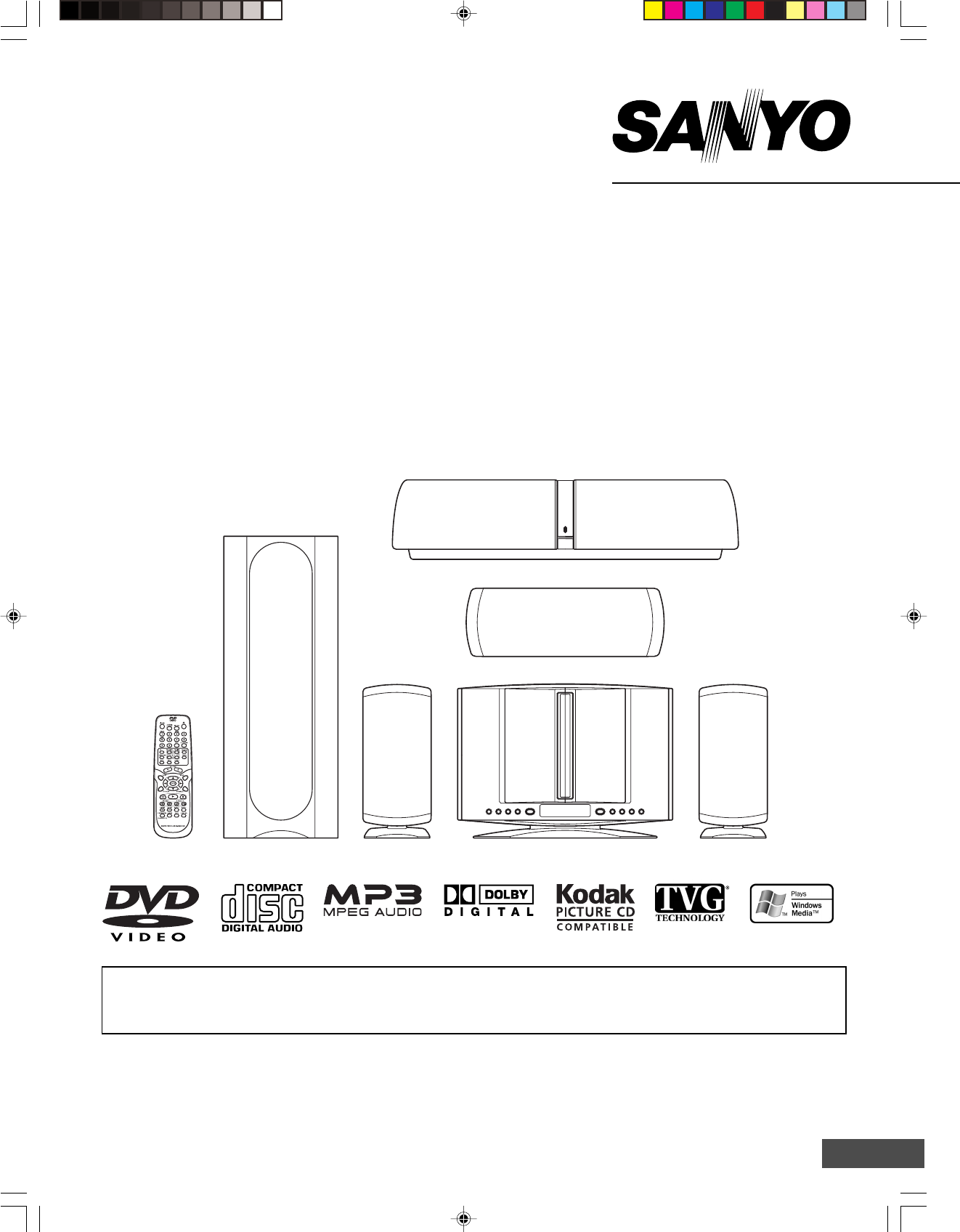
DVD Home Theater System
1AD6P1P2104-- DWM-4500, Issue Number 1
DWM-4500
SANYO’S HELP-LINE
Call the toll-free number below if you have any difficulties operating this product.
1-800-813-3435 (Weekdays: 7:30 AM - 4:00 PM Central Time)
TM
English
Please Read This Manual.
Because DVD is a new technology, we recommend that you read this manual carefully before connecting your DVD
Home Theater System and operating it for the first time.
Keep the manual in a safe place for future reference.
-E1-
CONTENTS
Accessories ......................................................................... E2
Safety Certification ............................................................. E3
For Safe and Efficient Operation ....................................... E3
Warning for Transmitter ..................................................... E4
Controls ............................................................................... E5
Multi-Brand TV Remote Control......................................... E6
Basic Connections .............................................................. E8
System Cable Connection ............................................... E8
Speaker Connections .................................................... E10
Speaker Placement ........................................................ E11
Using the Rear Speaker in Wireless Mode ................... E12
Using the Rear Speaker in Wired Mode ........................ E12
If Using the External Speaker (Not Supplied) Instead of
the Rear Speaker... ....................................................... E12
Conventional TV Connection ......................................... E13
Using RF Modulator ................................................. E14
Progressive-scan TV Connection .................................. E15
FM Antenna Connection ................................................ E16
Additional Connection Examples ................................... E16
Power Supply ................................................................ E16
Before Operation ............................................................... E17
Common Operation ....................................................... E17
Selecting Surround Mode .............................................. E18
Adjusting the Speaker Volume Balance ........................ E19
Adjusting the Sub-woofer Level ..................................... E19
Playable Discs ................................................................... E20
Disc Playback .................................................................... E21
Preparations .................................................................. E21
Basic Playback .............................................................. E22
Selecting Picture Mode ................................................. E22
Stopping Playback ......................................................... E23
Continuing Playback from Where You Stopped
Watching (LAST MEMO PLAY), for DVD only ............... E23
Selecting a DVD Menu .................................................. E23
Selecting a Top Menu [DVD] ......................................... E23
Chapter (Track) Skip ..................................................... E23
Title Search [DVD] ......................................................... E24
Chapter Search [DVD] ................................................... E24
Time Search [DVD] ........................................................ E24
Time Search [CD] .......................................................... E24
Track Search [CD] ......................................................... E24
Fast Playback ................................................................ E25
Slow Motion Playback [DVD] ......................................... E25
Still Picture (Pause) ....................................................... E25
Frame by Frame Advance Playback [DVD] ..................... E25
Picture Zoom [DVD] ...................................................... E25
Viewing from a Desired Camera Angle
(Multi-Angle) [DVD] ....................................................... E26
Designated Range Repeat Playback (A-B Repeat) ...... E26
Repeat Playback ........................................................... E26
Random Playback [CD] ................................................. E27
Programmed Playback [CD] .......................................... E27
Selecting Subtitle Language [DVD] ............................... E28
Selecting Audio Soundtrack Language
(Multi-Language) [DVD] ................................................. E28
Selecting On-Screen Information .................................. E28
TVGuardian Operation ...................................................... E29
Before Setting ................................................................ E29
Setting TVGuardian ....................................................... E29
How It Works After Setting TVGuardian ........................ E30
MP3/WMA CD Operation ................................................... E31
Before Starting .............................................................. E31
MP3 CD Playback ......................................................... E31
Picture Disc Operation ..................................................... E32
Before Starting .............................................................. E32
Kodak Picture/JPEG CD Playback ................................ E32
Initial Settings.................................................................... E33
Setting Language .......................................................... E33
Setting Display .............................................................. E34
Setting Audio ................................................................. E36
Setting Parental ............................................................. E37
Language Code List ...................................................... E38
Listening to the Radio (FM Only) ..................................... E39
Preparation .................................................................... E39
Automatic/Manual Tuning .............................................. E39
To Preset Stations ......................................................... E39
Listening to Preset Stations ........................................... E39
Enjoying Other Sources ................................................... E40
Sleep Timer Operation ...................................................... E40
Maintenance ...................................................................... E40
Troubleshooting Guide ..................................................... E40
Specifications .................................................................... E42
Warranty ............................................................................. E43
IMPORTANT INFORMATION:
To connect this DVD Home Theater System to a TV, TV must have a Video input jack (RCA-type) at least. You cannot
connect it to an antenna terminal of TV.
To operate the built-in TVGuardian®
This unit has the built-in TVGuardian® Foul Language Filter (TVG®).
When a disc supporting closed caption is played, it will mute the audio during the entire phrase containing offensive
language. For more details, see page E29.
-E2-
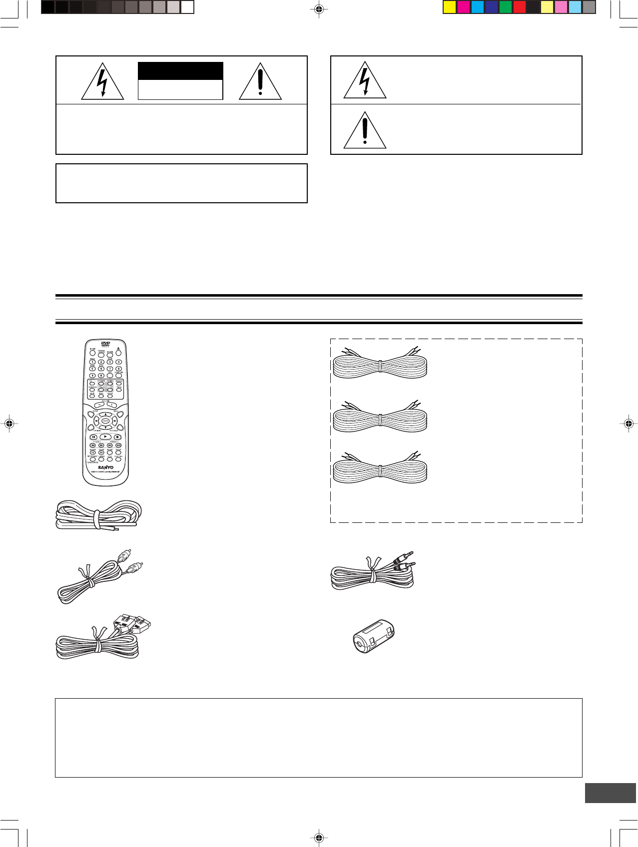
Ferrite core x 2
This symbol indicates that dangerous voltage
constituting a risk of electric shock is present
within this unit.
This symbol indicates that there are impor-
tant operating and maintenance instructions
in the literature accompanying this unit.
WARNING: TO PREVENT FIRE OR SHOCK HAZARD,
DO NOT EXPOSE THIS APPLIANCE TO RAIN OR
MOISTURE.
CAUTION: TO PREVENT THE RISK OF ELECTRIC
SHOCK, DO NOT REMOVE COVER (OR BACK).
NO USER-SERVICEABLE PARTS INSIDE.
REFER SERVICING TO QUALIFIED SERVICE PERSONNEL.
WARNING: UNAUTHORIZED RECORDING OF COPY-
RIGHTED MATERIAL MAY VIOLATE APPLICABLE
COPYRIGHT LAWS. THE MANUFACTURER ASSUMES
NO RESPONSIBILITY FOR UNAUTHORIZED DUPLICA-
TION, USE OR OTHER ACTS WHICH INFRINGE UPON
THE RIGHTS OF COPYRIGHT OWNERS.
CAUTION
RISK OF ELECTRIC SHOCK
DO NOT OPEN
ACCESSORIES
RB-DWM4500MT wireless remote control
Video cable
FM indoor antenna lead wire
Either the main unit or remote control can be operated. However, for convenience, this instruction manual explains
operation using the remote control.
Note:
This handling description is printed prior to product development.
When a part of the product specification must be changed to improve operability or other functions, priority is given to the product
specification itself. In such instances, the instruction manual may not entirely match all the functions of the actual product.
Therefore, the actual product and packaging, as well as the name and illustration, may differ from the manual.
Front left speaker cable
Length: Approx. 16.4 feet (5 meters)
(Black and White)
Front right speaker cable
Length: Approx. 16.4 feet (5 meters)
(Black and Red)
Front center speaker cable
Length: Approx. 16.4 feet (5 meters)
(Black and Green)
Assistance speaker cable for rear
speaker
Length: Approx. 23 feet (7 meters)
The speaker cables are packed in the speaker package.
System cable
-E3-
•Do not damage the power cord.
•When not in use, disconnect the power cord from the outlet.
Grasp the plug, not the cord, when disconnecting the unit.
•If water should enter the unit, electrical shock or a malfunction
may result. Use in an area where there is low humidity and
little dust.
• Do not disassemble or alter the unit in any way.
•Do not use the unit in areas where extremes in temperature
occur (below 40°F (5°C) or exceeding 95°F (35°C)), or where
it may be exposed to direct sunlight.
•Because of the DVD video player’s extremely low noise and
wide dynamic range, there is a tendency to set the volume on
the amplifier higher than necessary. Doing so may produce
an excessively high output from the amplifier which can
cause damage to your speakers. Please be careful in this
regard.
•Sudden changes in the surrounding temperature can cause
dew to form on the optical pickup lens inside the unit. Under
this condition the unit may be unable to operate properly. If
this should occur, remove the disc and allow the unit to adjust
to the surrounding temperature.
FOR SAFE AND EFFICIENT OPERATION
CAUTION:
The sub-woofer (powered speaker) and the rear speaker
(powered speaker) must be placed in a well ventilated area.
Do not place any object on the top of these units.
Do not block ventilation holes.
The cabinet of these units warms up when it is used for a long
time, but it is not a malfunction.
•When carrying the unit, be sure to remove a disc which
may be inside and turn the power off. Then unplug the
power cord from the AC outlet after 10 seconds. Carrying
the unit with a disc inside may damage the disc and/or
the unit.
•The unit is automatically set to the Screen Saver mode
after approximately 5 minutes have elapsed under the
stop or pause mode.
SAFETY CERTIFICATION
This unit is made and tested to meet exacting safety
standards. It meets UL and FCC requirements and com-
plies with safety performance standards of the U.S. Depart-
ment of Health and Human Services.
CAUTION - USE OF CONTROLS OR ADJUSTMENTS
OR PERFORMANCE OF PROCEDURES OTHER THAN
THOSE SPECIFIED HEREIN MAY RESULT IN HAZARD-
OUS RADIATION EXPOSURE.
THIS UNIT SHOULD NOT BE ADJUSTED OR REPAIRED
BY ANYONE EXCEPT PROPERLY QUALIFIED SER-
VICE PERSONNEL.
FCC INFORMATION
This device complies with Part 15 of the FCC Rules.
Operation is subject to the following two conditions:
(1) This device may not cause harmful interference, and (2) this
device must accept any interference received, including
interference that may cause undesired operation.
CAUTION:
Changes or modifications not expressly approved by the party
responsible for compliance could void the user’s authority to
operate this equipment.
Note:
This equipment has been tested and found to comply with the
limits for a Class B digital device, pursuant to Part 15 of the FCC
Rules. These limits are designed to provide reasonable protection
against harmful interference in a residential installation. This
equipment generates, uses and can radiate radio frequency
energy and, if not installed and used in accordance with the
instructions, may cause harmful interference to radio
communications. However, there is no guarantee that interference
will not occur in a particular installation. If this equipment does
cause harmful interference to radio or television reception, which
can be determined by turning the equipment off and on, the user
is encouraged to try to correct the interference by one or more of
the following measures:
•Reorient or relocate the receiving antenna.
•Increase the separation between the equipment and receiver.
•Connect the equipment into an outlet on a circuit different
from that to which the receiver is connected.
•Consult the dealer or an experienced radio/TV technician for
help.
-E4-
WARNING FOR TRANSMITTER
Important Information!
1. Explicitly specify to all users the technical instructions and
the scope of use defined in the related documents and
provide the explanation about all the control methods,
adjusting procedures and usage of switches.
2. Do not change the emitter frequency nor boost the emitter
power (including the power of excess load wireless frequency
power amplifier). Do not put up an external antenna nor use
any other remodeled antenna.
3. In use of this unit, avoid any act which interferes with legal
wireless communication services. Should any interference
arise, immediately stop using this unit, remove the interference,
and avoid such an act in the future.
4. When micro-power wireless equipment is used, avoid
interference with wireless communication services or emissive
interference from industrial, scientific and medical treatment
equipment.
5. Do not use this unit in an aircraft or near an airport.
Warning for using the sub-woofer with a built-
in transmitter
•Keep the sub-woofer (powered speaker) at least 8 feet
away from all heart pacemakers!
The radio waves may disrupt the operation of the
pacemaker.
•Do not operate this unit in medical Institutions, hospitals
or near medical equipment!
The radio waves may cause nearby equipment to
operate incorrectly or fail.
•When other equipment or a medical apparatus operates
incorrectly or fails to operate due to radio wave
interference, stop using this unit!
The radio waves may cause nearby equipment to
operate incorrectly or fail.
In-plant radio stations, and special low-power radio stations for
movable body identification used for production lines and
amateur radio stations as well as industrial, scientific and
medical equipment (such as microwave ovens) use the same
frequency band used by this unit.
1. Before using this unit, make sure that no in-plant radio
stations or special low-power radio stations for movable
body identification or amateur radio stations are operated
nearby.
2. If this unit should adversely radio-interfere with an in-plant
radio station for movable body identification, immediately
change the frequency band used by this unit or stop emitting
electric waves and consult the your dealer or SANYO service
center about measures for avoiding interference (for
example, installation of a partition).
3. If any trouble occurs such as this unit causing adverse radio
interference with special low-power radio stations for
movable body identification or an amateur radio station,
contact your SANYO dealer or SANYO service center.
Forbidden
Forbidden
-E5-
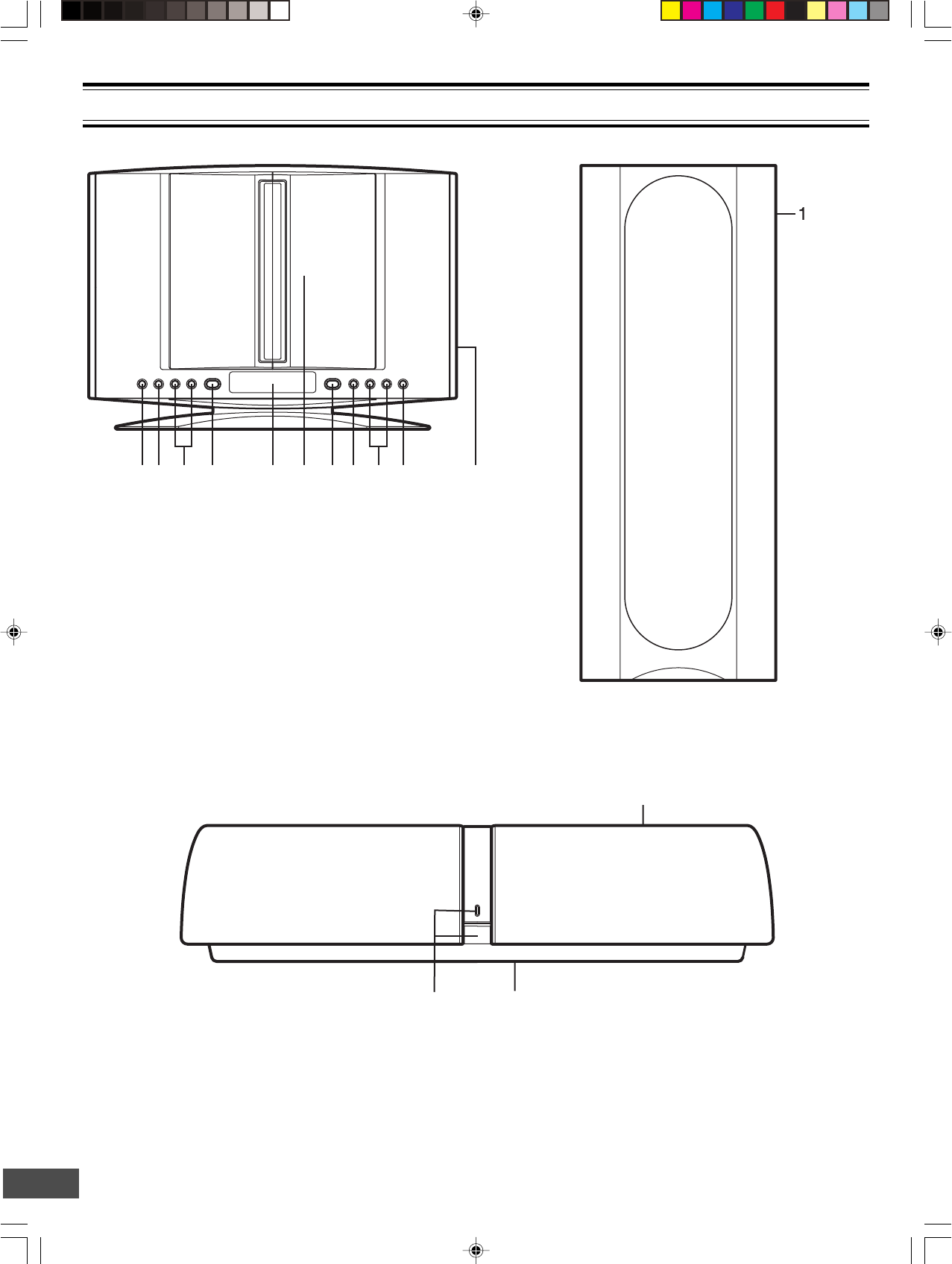
Main unit (DVD Receiver)
Rear speaker (Powered speaker)
1. Power switch (z/ON) and power indicator
2. Speaker switch (SPEAKER, back side) (See page E12.)
1. Frequency switch (FREQUENCY, back side) (See page E12.)
Sub-woofer (Powered speaker)
3. Frequency switch (FREQUENCY, top side) (See page E12.)
2
3
1
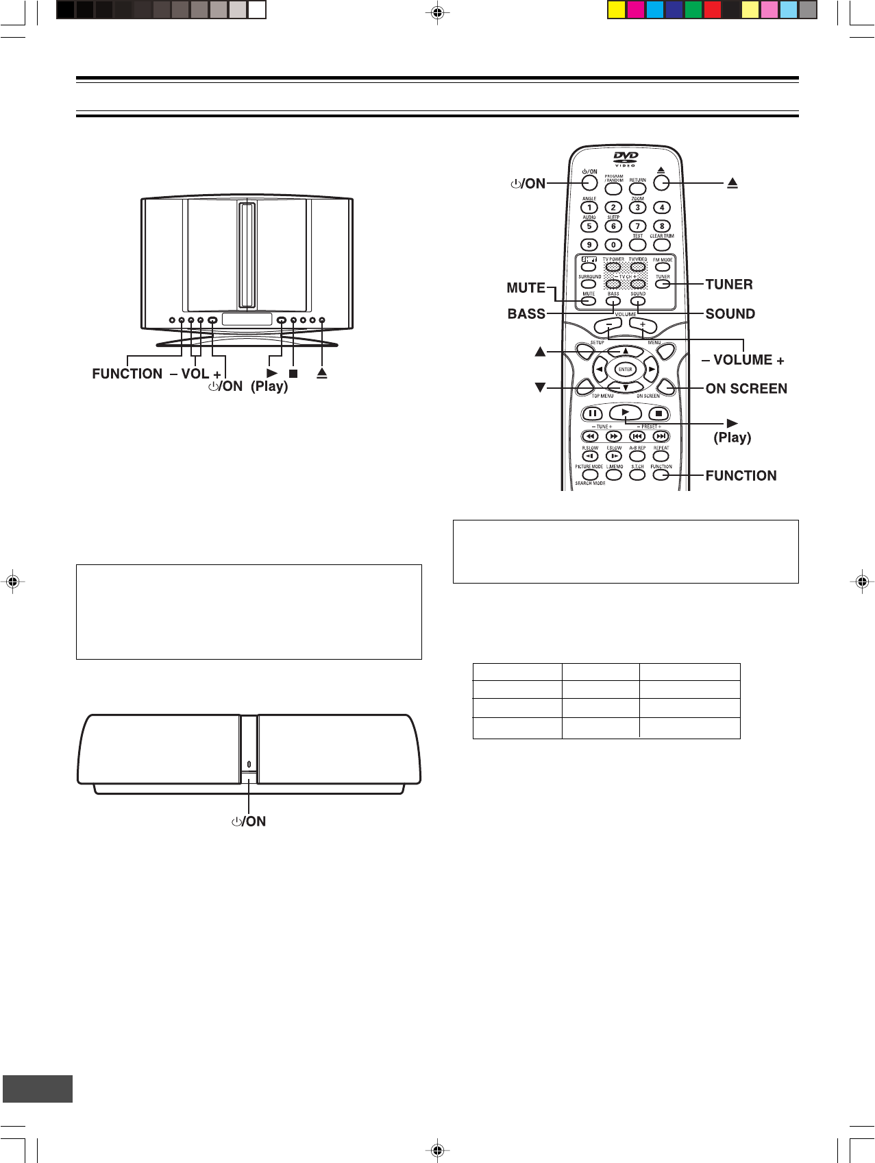
CONTROLS
1. Remote sensor (IR)
2. Function button (FUNCTION)
3. Volume buttons (- VOL +)
4. Power button (z/ON)
5. Display
6. Disc door
7. Play button (a)
8. Stop button (n)
9. Skip/Next/Previous/Preset tuning buttons
(f/e, -PRESET +)
10. Open/Close button (q)
11. S-video and Component video out select switch
(VIDEO OUT SELECT, right side)
(See pages E13 and E15.)
12 3 4 5 6 7 8 9 10 11
-E6-
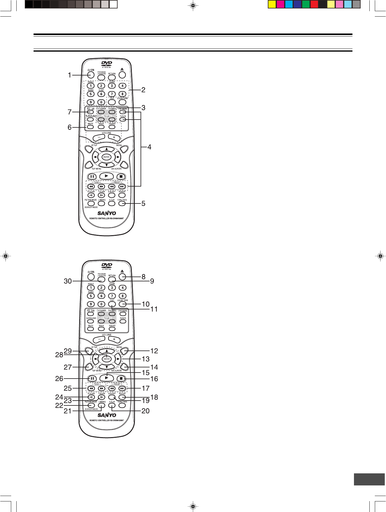
1. Power button (z/ON)
2. Number and other function buttons
These buttons are used as number buttons and as function
buttons of each name.
•When using as a number button, press the appropriate
button directly.
•When using as a function button of each name, press the
appropriate button while holding the SHIFT button down.
Number buttons (1 – 9, 0)
Angle button (ANGLE)
Zoom button (ZOOM)
Audio button (AUDIO)
Sleep button (SLEEP)
3. TV control buttons
Power button (TV POWER)
TV/VIDEO select button (TV/VIDEO)
Channel scanning buttons (-TV CH +)
4. Tuner controls
FM mode button (FM MODE)
Tuner function button (TUNER)
Tuning buttons (- TUNE +)
Preset tuning buttons (- PRESET +)
5. Function button (FUNCTION)
6. Amplifier controls
Surround button (SURROUND)
Muting button (MUTE)
Bass button (BASS)
Sound preset button (SOUND)
Volume buttons (- VOLUME +)
7. Shift button (SHIFT)
8. Open/Close button (q)
9. Return button (RETURN) (See page E23.)
10. Clear/Trim button (CLEAR, TRIM)
Note:
At Trimming mode, press the button while holding the SHIFT
button down. (See page E19.)
11. Test tone button (TEST) (See page E19.)
12. Menu button (MENU)
13. Directional arrow buttons (o, a, p, b)
14. On-screen display button (ON SCREEN)
15. Play button (a)
16. Stop button (n)
17. Skip/Next/Previous buttons (f, e)
18. Repeat button (REPEAT)
19. A-B repeat button (A-B REP)
20. Subtitle change button (S.T.CH)
21. Last memory button (L.MEMO)
22. Picture mode/Search mode button
(PICTURE MODE/SEARCH MODE)
Note:
At Search mode, press the button while holding the SHIFT
button down.
23. Forward slow button (F.SLOW I a)
24. Reverse slow button (R.SLOW b I)
25. Fast forward/Fast reverse buttons (d, c)
26. Pause/Step button (k)
27. Top menu button (TOP MENU)
28. Enter button (ENTER)
29. Setup button (SETUP)
30. Program/Random play button (PROGRAM/RANDOM)
MULTI-BRAND TV REMOTE CONTROL
-E7-
To set the remote control code for TV
This remote control can operate the basic functions of TVs made
by the manufacturers listed below.
To enter the remote control code for your brand of TV, follow the
steps below.
1. In the chart below, find the code corresponding to your brand
of TV.
2. While holding down [TV POWER], enter the 2-digit code
using the number buttons [0 - 9], then release [TV POWER].
•The remote control is now set to operate your TV.
TV brands Code
ADMIRAL 05, 10, 13
EMERSON 17
FISHER 03
GE 07
GOLD STAR 01
HITACHI 02
JVC 15
MAGNAVOX 08
MATSUSHITA 12, 18
MITSUBISHI 14
PANASONIC 12, 18
QUASAR 12, 18
RCA 06
SAMSUNG 16
SANYO 03
SHARP 00, 13
SONY 11
TECHNOL ACE 05
TOSHIBA 04
ZENITH 09, 10
Notes:
•Only remote-controlled TVs can be operated using this remote
control. (Refer to your TV instruction manual for more details.)
•There may be some TV models that cannot be operated with
this remote control. If this is the case, use the original remote
control supplied with the TV.
IMPORTANT NOTE:
If the batteries in the remote control are changed, the code
settings for the TV must be re-entered.
Write your code number below for future reference.
TV:
Note:
This remote control cannot operate your VCR.
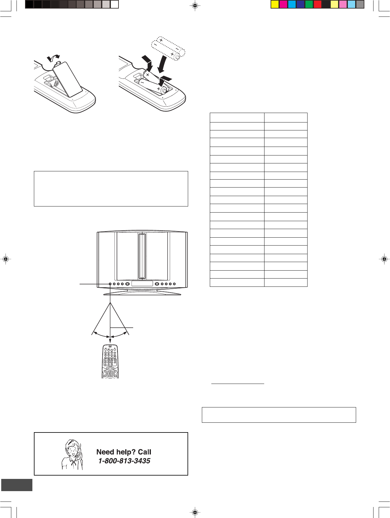
Inserting batteries
12
Note:
Remove the batteries if the remote control is not to be used for a
month or more. Batteries left in the unit may leak and cause
damage.
IMPORTANT NOTE:
SPENT OR DISCHARGED BATTERIES MUST BE
RECYCLED OR DISPOSED OF PROPERLY IN COMPLIANCE
WITH ALL APPLICABLE LAWS.
FOR DETAILED INFORMATION, CONTACT YOUR LOCAL
COUNTY SOLID WASTE AUTHORITY.
Remote control range
Two "AA" batteries
(not supplied)
Remote sensor
Within approx. 20 feet
(6 meters)
30°30°
-E8-
BASIC CONNECTIONS
Do not connect the power cord to a
120V AC 60Hz outlet until all connec-
tions have been made.
System cable from Main unit
(DVD Receiver)
Main unit (DVD Receiver)
Sub-woofer
(Powered speaker)
System cable to Sub-woofer (Powered speaker)
System cable
Attach the ferrite core.
Ferrite core
System Cable Connection
-E9-
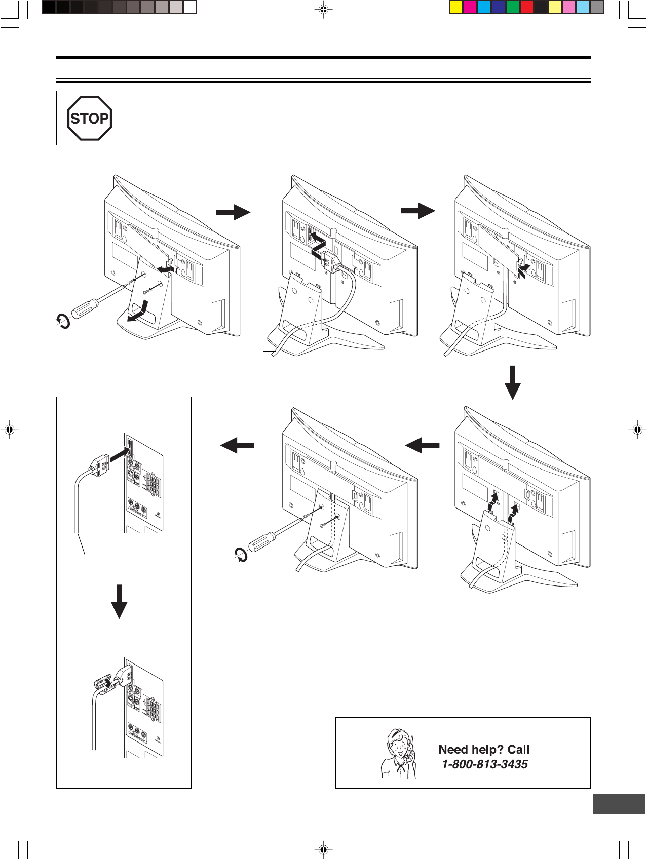
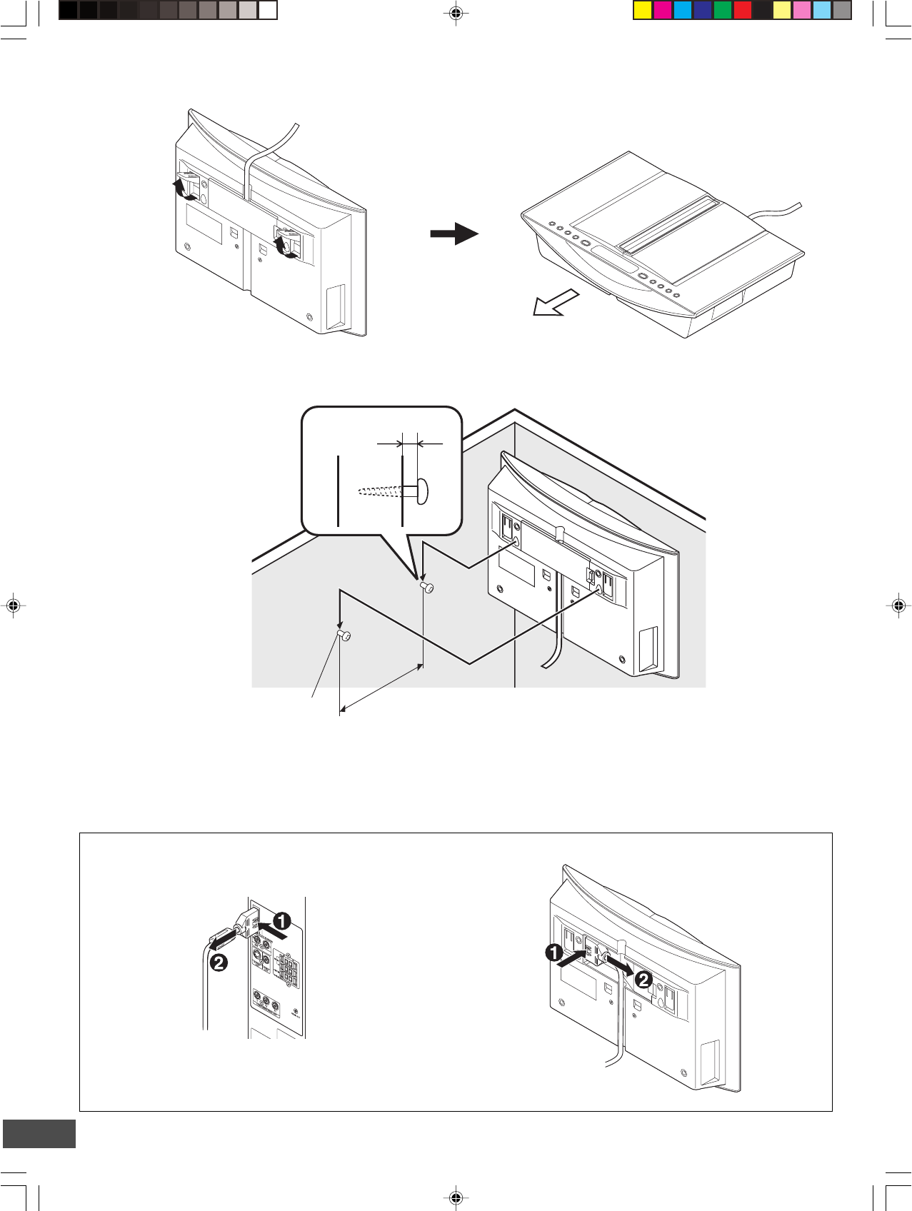
Example: To use Main unit horizontally
Example: To hang Main unit on a wall
To unplug the system cable, pull out the plug (2) while pressing (1) down.
Main unitSub-woofer (Powered speaker)
Note:
Take care when installing it. It may cause damage or serious injury should it fall from its mountings.
Approx. 3/16 inch (5mm)
Approx. 5.4 inch (144mm)
Round head screw (not supplied)
Toward you
-E10-
After all speaker
connections have been
made, attach the ferrite
core.
Ferrite core
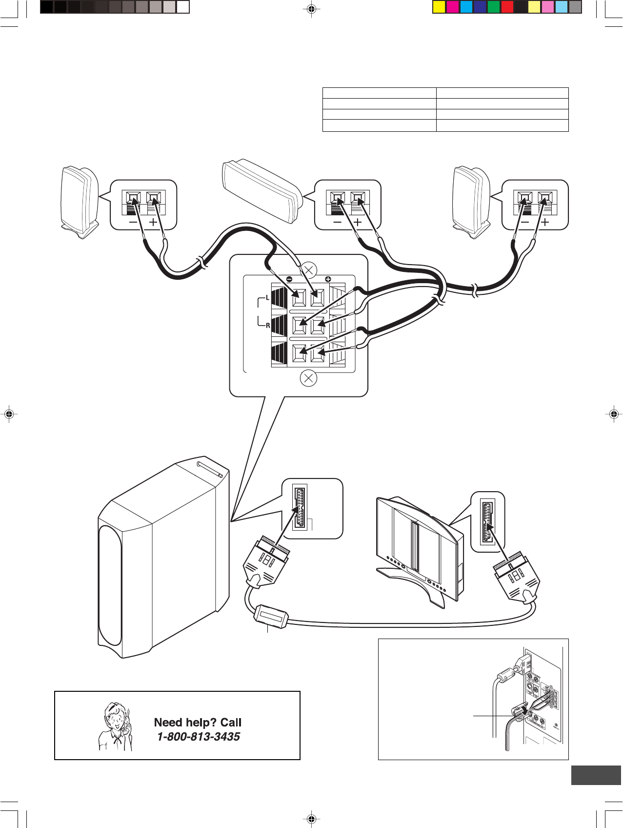
RedWhite Green BlackBlack Black
Front right speakerFront left speaker Center speaker
Sub-woofer (Powered speaker)
System cable
Main unit (DVD Receiver)
Ferrite core
Note:
Do not connect the power cord to a 120V AC 60Hz outlet until all connections have been made.
Speaker Wire Color Use
Black and White Front left speaker
Black and Red Front right speaker
Black and Green Center speaker
Speaker Connections
To achieve proper stereo reproduction, connect the speaker
wires without shorting to adjacent wires as shown below.
SYSTEM (TO DVD RECEIVER)
SPEAKERS(4Ω)
FRONT
CENTER
-E11-
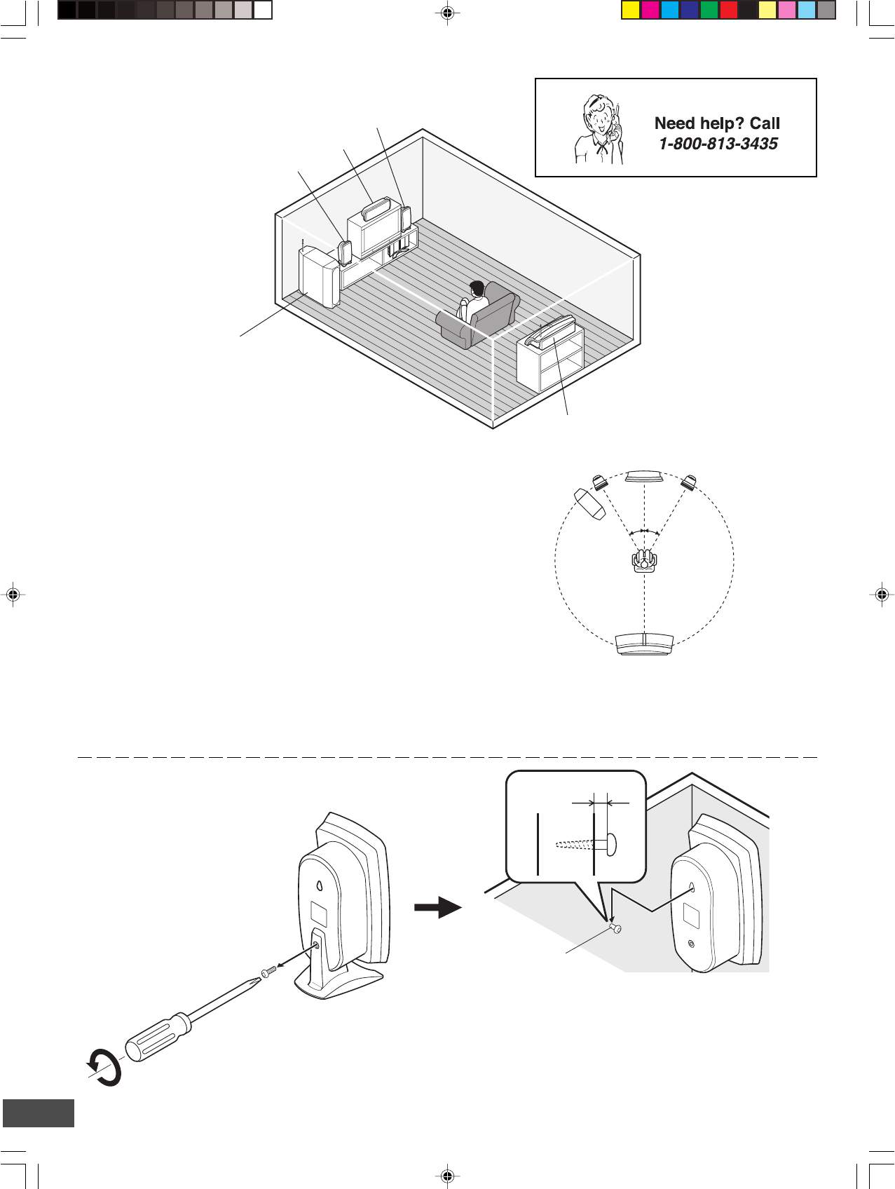
Example: To hang the speaker on a wall Approx. 1/8 inch (3 mm)
Round head screw
(not supplied)
Note:
Take care when installing the speakers. They may cause
damage or serious injury should they fall from their
mountings.
Keep both the screw and stand for future use.
Unscrew and remove the stand.
Speaker Placement
Center speaker
Rear speaker (Powered speaker)
Sub-woofer
(Powered speaker)
Place it near the front speaker.
However, do not place it in front of
the TV.
Front left speaker
Front right speaker
The front (left and right) and center speakers have built-in magnetic
stray field compensation. They may be placed close to a TV
without affecting the color purity.
Place the front left and right speakers either side of the TV.
Place the center speaker directly above the TV.
The front, center, and rear speakers should be placed at
approximately the same distance from the listening position.
Place the rear speaker behind the listening position, on the floor
or approximately 2 feet ~ 3 feet 3 inches (60 cm ~ 1 meter) higher
than ear level.
Keep enough distance between the subwoofer and the TV so as
not to garble the TV screen.
Front left speaker Front right speaker
Center speaker
Rear speaker
Sub-woofer
Notes:
• The angles in the diagram are approximate.
•Please refer to “Setting Audio” on page E36.
•Set the TV’s built-in speaker volume to minimum.
30°30°
-E12-
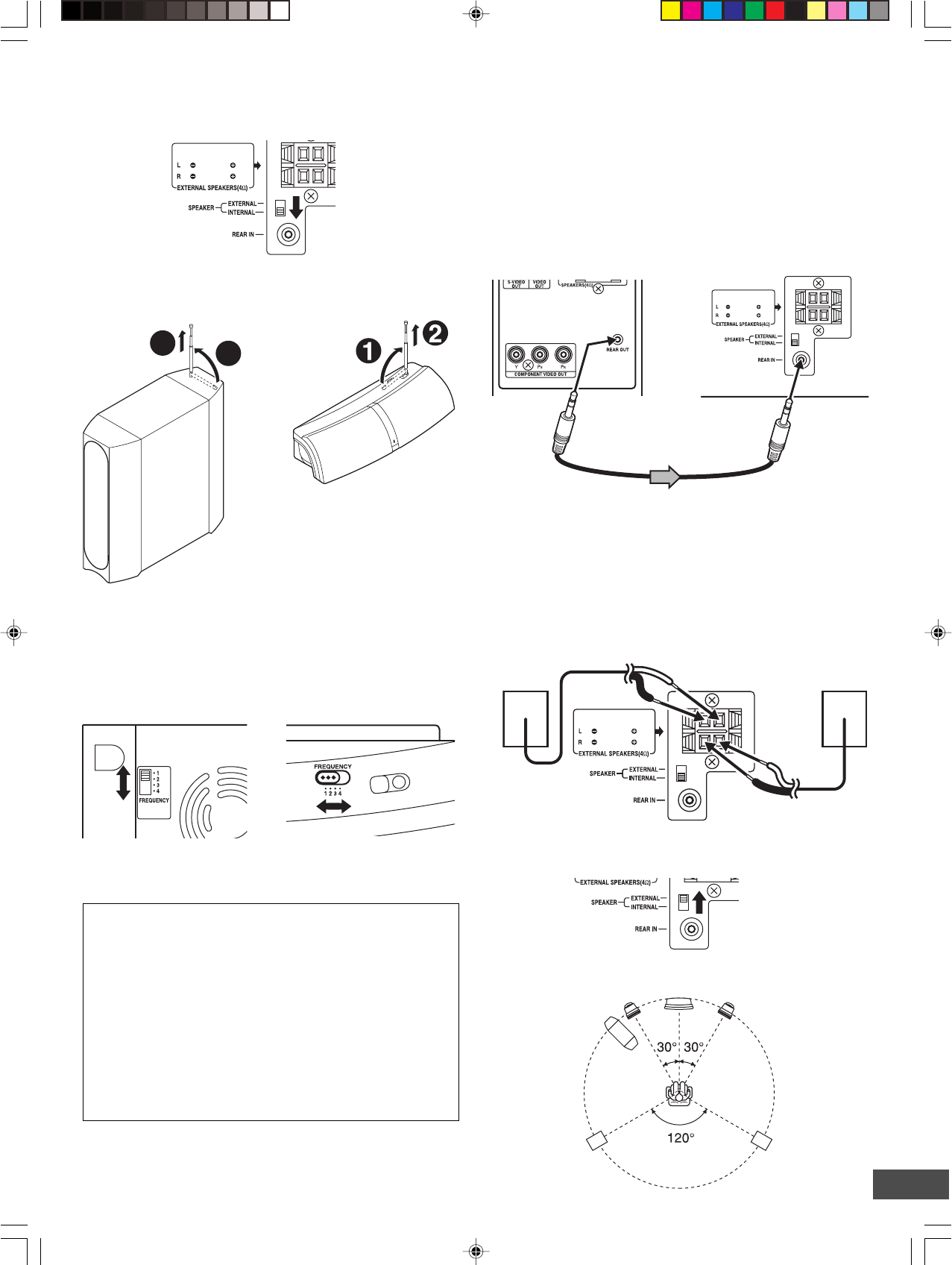
Using the Rear Speaker in Wireless Mode
1. Set the SPEAKER switch of the rear speaker to the INTERNAL
position.
Changing the frequency setting
If noise (or skipping sound) is heard when using rear speaker in
wireless mode, change the setting of the FREQUENCY switch
on both sub-woofer and rear speaker.
Match the number on both sub-woofer and rear speaker.
It may improve the sounds.
The following four frequencies are available.
FREQUENCY switch
1(914.1 MHz)
2(914.5 MHz)
3(914.9 MHz)
4(915.3 MHz)
Using the Rear Speaker in Wired Mode
Because the rear speaker is the wireless type, it is not necessary
to connect the assistant speaker cable under normal connections.
If noise is caused to the rear speaker when used in wireless
mode, change the setting of the FREQUENCY switch on both
sub-woofer and rear speaker (Refer to the left column).
If noise is still caused, turn the power off first and connect the
rear speaker to the sub-woofer using the supplied assistant
speaker cable. In this case, the audio signal is sent to the rear
speaker through the assistant speaker cable.
Sub-woofer (powered speaker)
Assistant speaker cable
Note:
Adjust the distances between the sub-woofer and the rear speaker
to be suitable shorter than approx. 23 feet cord length.
If Using the External Speaker (Not Supplied)
Instead of the Rear Speaker...
1. Connect the external speaker (4 Ω, more than 50 Watts for
each speaker, not supplied) to the EXTERNAL SPEAKERS
terminal.
Front left speaker Front right speaker
Center speaker
External rear
left speaker
(not supplied)
Sub-woofer
External rear
right speaker
(not supplied)
2. Pull out gently the antenna vertically.
• Try not to hold, bend, or twist the antenna.
Sub-woofer
(Powered speaker)
Rear speaker
(Powered speaker)
CAUTION:
Keep it out of reach of young children who might damage
it.
3. Set the FREQUENCY switch to “1”, “2”, “3” or “4”.
Match the number on both sub-woofer and rear speaker.
2. Set the SPEAKER switch to the EXTERNAL position.
3. Place the external speaker as shown in figure.
1
2
Sub-woofer
(Powered speaker)
External rear
right speaker
(not supplied)
External rear
left speaker
(not supplied)
Rear speaker
(Powered speaker)
Rear speaker
(Powered speaker)
Rear speaker (Powered
speaker)
To REAR OUT
jack
To REAR IN
jack
-E13-
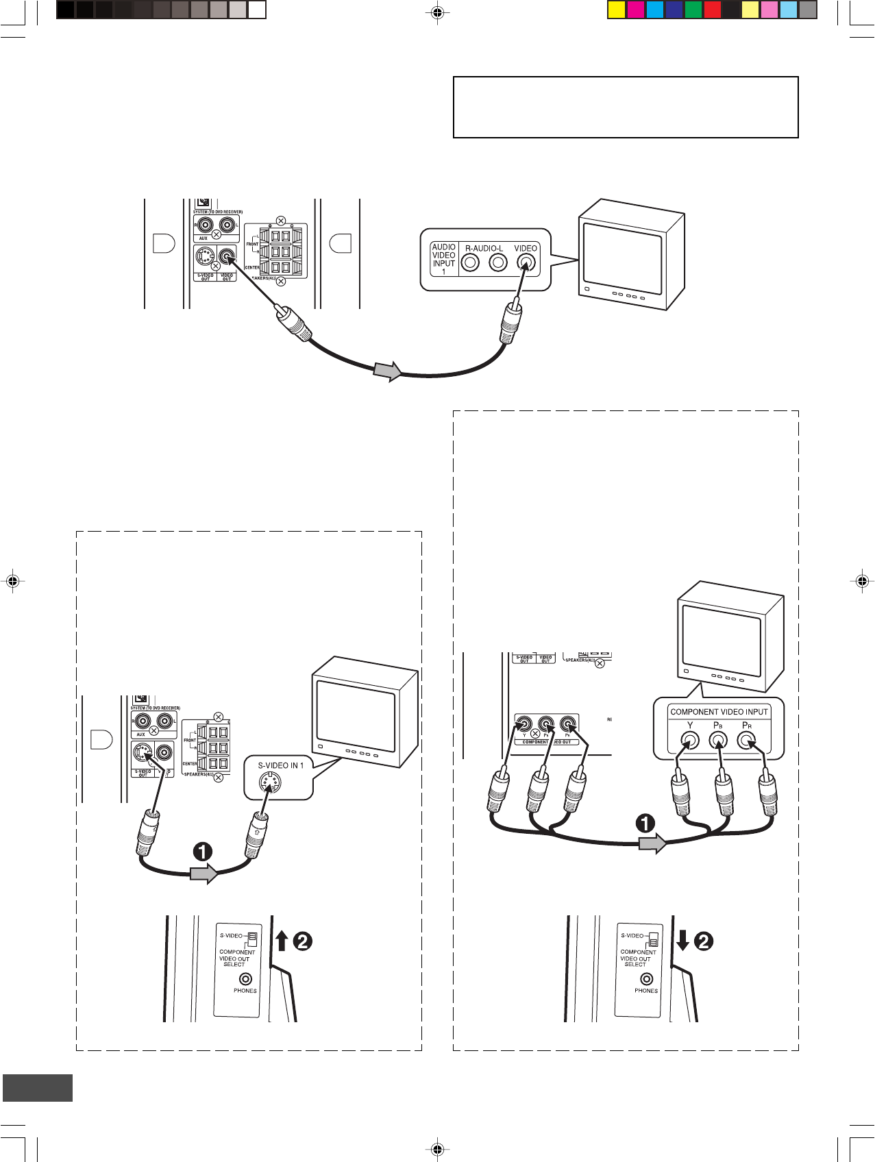
Conventional TV Connection
Using VIDEO OUT jack
Connect the Video cable with yellow connectors (supplied)
between the VIDEO OUT jack of the sub-woofer and the VIDEO
INPUT jack on the TV.
Notes:
•Please refer to your TV instruction manual.
•When you connect the subwoofer to your TV, be sure to turn
off the power and disconnect both units from the wall outlet
until all the connections have been made.
•Do not connect the VIDEO OUT, S-VIDEO OUT, and
COMPONENT VIDEO OUT jacks of the sub-woofer to a VCR
directly. The playback picture will be distorted because DVD
video discs are copy protected.
*S-video cable (not supplied)
TV with S-VIDEO
INPUT jack
Sub-woofer (Powered speaker)
*Please consult your local audio/video dealer.
TV
Important Information:
To connect the unit to a TV, TV must have a Video input jack
(RCA-type) at least. You cannot connect it to an antenna
terminal of TV.
Video cable (supplied)
To VIDEO INPUT jack
To VIDEO OUT jack (Yellow)
Sub-woofer (Powered speaker)
Using S-VIDEO OUT jack
Note:
Please follow the steps before turning on the power.
1. If your TV has the S-VIDEO INPUT jack, connect the *S-
video cable (not supplied) as shown in figure. (The VIDEO
OUT jack connection is not necessary.)
You can enjoy clearer picture playback.
Using COMPONENT VIDEO OUT jacks
Note:
Please follow the steps before turning on the power.
1. If your TV has the COMPONENT VIDEO INPUT jacks,
connect the *Component video cable (not supplied) as
shown in figure.
(The VIDEO OUT or S-VIDEO OUT jack connection is not
necessary.)
You can enjoy high quality picture playback.
TV with COMPONENT
VIDEO INPUT jacks
*Component Video cable (not supplied)
Red
Blue
Green
Sub-woofer (Powered speaker)
Red
Blue
Green
2. Set the VIDEO OUT SELECT switch to the S-VIDEO position.
2. Set the VIDEO OUT SELECT switch to the COMPONENT
position.
Main unit (Right side) Main unit (Right side)
-E14-
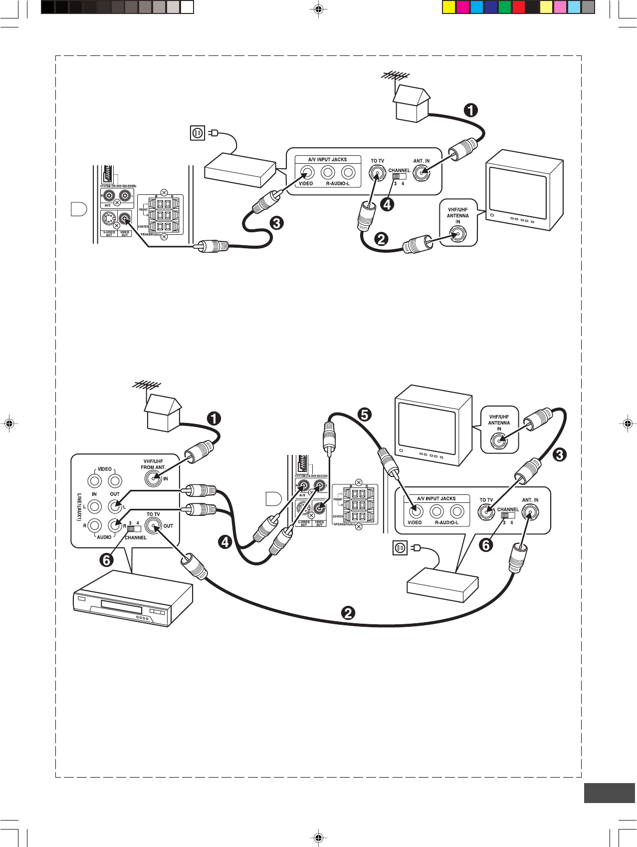
Using RF Modulator
If your TV does not have a Video input jack and has an antenna
terminal only, please purchase the *RF Modulator (not supplied).
(*Please consult your audio/video dealer.)
Example: Sub-woofer, TV and RF Modulator connections
1. Connect the antenna cable (not supplied) to the ANT. IN
terminal of the RF Modulator.
2. Connect the 75-ohm coaxial cable (not supplied) between
the TO TV terminal of the RF Modulator and the VHF/UHF
ANTENNA IN terminal of the TV.
3. Connect the Video cable with yellow connectors (supplied)
between the VIDEO OUT jack of the sub-woofer and the
VIDEO input jack of the RF Modulator.
Example: Sub-woofer, VCR, TV and RF Modulator connections
1. Connect the antenna cable (not supplied) to the VHF/UHF
FROM ANT IN terminal of the VCR.
2. Connect the 75-ohm coaxial cable (not supplied) between
the TO TV OUT terminal of the VCR and the ANT. IN
terminal of the RF Modulator.
3. Connect the 75-ohm coaxial cable (not supplied) between
the TO TV terminal of the RF Modulator and the VHF/UHF
ANTENNA IN terminal of the TV.
4. Connect the audio cables (not supplied) between the AUX
jacks of the unit and the AUDIO OUT jacks of the VCR. Use
the red connectors for the right-R jacks and the white
connectors for the left-L jacks.
5. Connect the Video cable with yellow connectors (supplied)
between the VIDEO OUT jack of the sub-woofer and the
VIDEO input jack of the RF Modulator.
6. Turn on the TV, and set the channel number (CHANNEL3 or
CHANNEL4) on all TV, VCR and RF Modulator, whichever
is not used for regular broadcasts in your area.
Note:
For more details, please refer to the instruction manual of the RF
Modulator.
4. Turn on the TV, and set the channel number (CHANNEL3 or
CHANNEL4) on both TV and RF Modulator, whichever is not
used for regular broadcasts in your area.
Note:
For more details, please refer to the instruction manual of the RF
Modulator.
To VIDEO OUT jack (Yellow)
To VIDEO OUT jack (Yellow)
Sub-woofer (Powered speaker)
Sub-woofer
(Powered speaker)
HiFi Stereo VCR
RF Modulator
RF Modulator TV
TV
-E15-
+
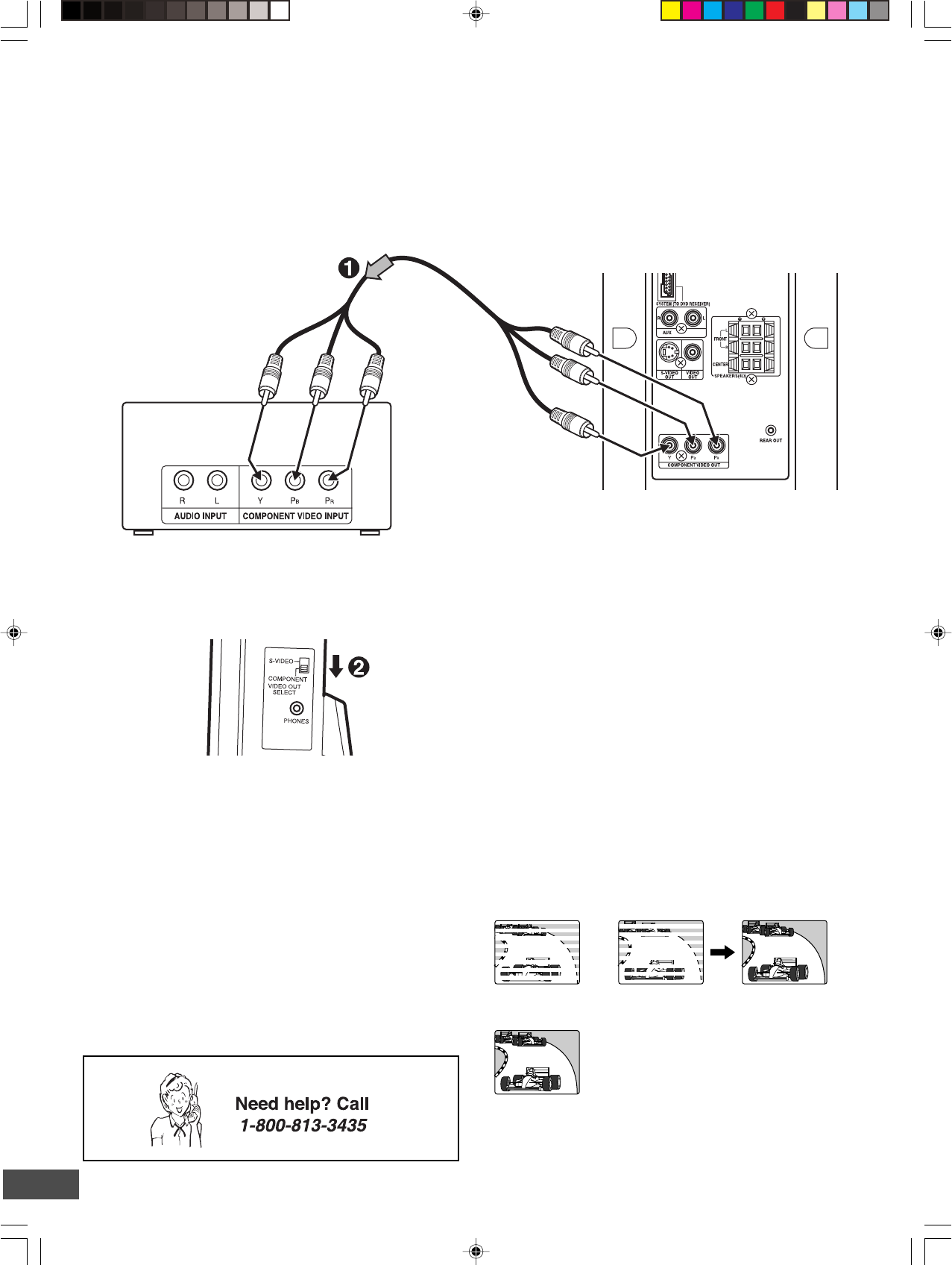
Note:
Please follow the steps before turning on the power.
1. Connect to the component video input jacks. (The VIDEO
OUT or S-VIDEO OUT jack connection is not necessary.)
*Please consult your local audio/video dealer.
*Component video cable (not supplied)
Green
Red
Blue
Green
Red
Blue
TV with progressive-scan capability
Progressive-scan TV Connection
Your TV must be capable of handling progressive scanning and have component video input capability.
2. Set the VIDEO OUT SELECT switch to the COMPONENT
position.
Progressive Scanning
While interlaced scanning produces one frame of video in two
fields, progressive scanning creates one frame in one field.
Conventional interlaced scanning constitutes one second with
30 frames (60 fields), but progressive scanning constitutes it with
60 frames from scratch. Progressive scanning can reproduce
sharper picture with high resolution for still image or other picture
containing long texts or horizontal lines.
This model has compliance with 525p (progressive) system.
Notes:
•Please refer to your TV instruction manual.
•When you connect the unit to your TV, be sure to turn off the
power and disconnect both units from the wall outlet until all
the connections have been made.
•Do not connect the unit to a VCR directly. The playback
picture will be distorted because DVD video discs are copy
protected.
Interlaced scanning
Progressive scanning
3. Set the unit to the PROGRESSIVE mode. See pages E21
and E35.
Sub-woofer (Powered speaker)
Main unit (Right side)
-E16-
PHONES
S-VIDEO
COMPONENT
VIDEO OUT
SELECT
PHONES jack
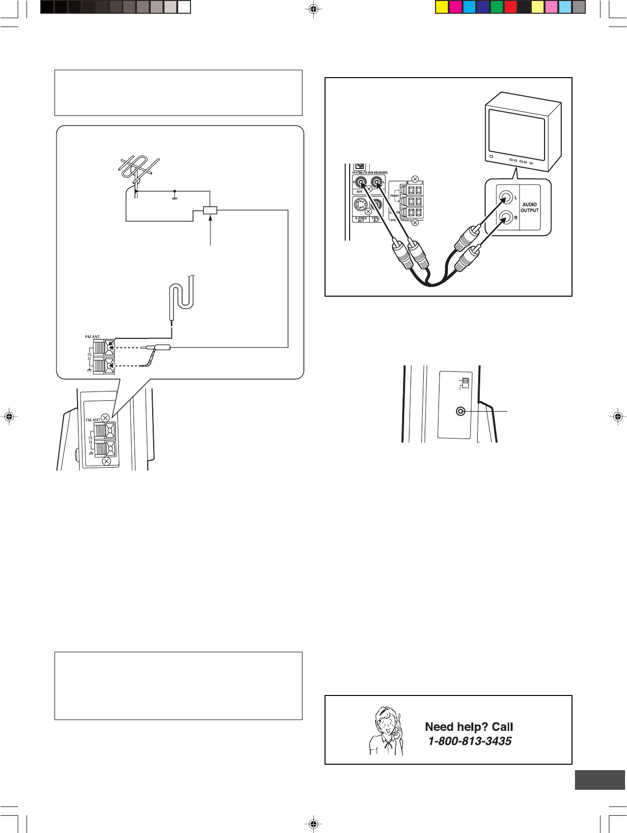
FM Antenna Connection
FM outdoor antenna
(not supplied)
Antenna discharge unit (not supplied)
FM indoor antenna
lead wire
75-ohm coaxial cable
(not supplied)
CAUTION:
When installing an outdoor antenna, follow the installation
instructions in the attached “IMPORTANT SAFETY
INSTRUCTIONS”.
Ground
Additional Connection Examples
Headphones jack (PHONES)
Connect a pair of stereo headphones with miniplug (8 ohms - 32
ohms, not available from SANYO) to the PHONES jack for
monitoring or for private listening. The speakers are automatically
disconnected when headphones are connected.
Audio cable (not supplied)
TV
To enjoy your TV sounds
If your TV has the audio output jacks,
connect an audio cable (not supplied)
from the audio output jacks of the TV to
the AUX jacks.
The FM indoor antenna lead wire is sufficient to receive most
local FM broadcasts and should be connected to the rear FM
75Ω terminal. Extend the antenna lead wire as straight as possible
and, while listening to the sound from the system, secure it in a
position where the best FM reception is found.
In fringe areas, or where reception is distorted or noisy, an FM
outdoor antenna (not supplied) should be connected instead of
the FM indoor antenna lead wire. The terminals will accept 75-
ohm coaxial cable.
Note:
To minimize noise...
•Do not place the antenna close to a TV or speaker.
Note to CATV system installer:
This reminder is provided to call the CATV system installer’s
attention to Section 820-40 of the NEC which provides guidelines
for proper grounding and, in particular, specifies that the cable
ground shall be connected to the grounding system of the
building, as close to the point of cable entry as practical.
Power Supply
(Sub-woofer and Rear Speaker)
Connect the power cord to a 120VAC 60Hz outlet.
The sub-woofer (powered speaker) and the rear speaker (powered
speaker) are equipped with a polarized plug. If you have difficulty
inserting the plug, turn it over and reinsert it. If these speakers
will not be used for a long time, disconnect the AC plug from the
AC outlet.
Notes:
•Before plugging the power cord into an AC outlet, make sure
that all the connections have been made.
•The sub-woofer (powered speaker) is not disconnected from
the AC power unless the power cord is unplugged from the
AC outlet.
Sub-woofer (Powered speaker)
Main unit (Right side)
Main unit (Left side)
-E17-
Common Operation
Turning the power on and off
Main unit (DVD Receiver)
BEFORE OPERATION
To reduce the volume temporarily (muting)
Press [MUTE] on the remote control. “MUTE” blinks on the
display.
To restore the previous volume setting, press [MUTE] again.
Selecting the sound mode
1. Press [SOUND] repeatedly to select the desired sound mode
(“BASS”, “TREBLE” or “NIGHT”).
2. Press the button as desired.
To turn the power off, press [z/ON] again.
Selecting the source
Press [FUNCTION] to select the desired source. Each time the
button is pressed, the display changes as follows:
DVD/CD v AUX v FM TUNER v DVD/CD...
•When the source selection is changed, disc playback
automatically stops.
Adjusting the volume
Press [VOLUME] + or - on the remote control (or press [VOL] + or
- on the main unit). The volume level appears on the display
(VOL 0 ~ VOL MAX).
Sound mode Press Display change
BASS p or o“-5” ~ “+5”
TREBLE p or o“-5” ~ “+5”
NIGHT ENTER “ON” or “OFF”
Note for “NIGHT” mode:
When enjoying a DVD disc with the volume set low at night,
select this mode. It enhances spoken lines making speech
clearer.
3. Repeat steps 1 to 2 for another sound mode.
4. Press [SOUND] repeatedly to close the display.
Bass boost system
Press [BASS] repeatedly to select the desired bass boost effect.
BOOST v BASS OFF v NORMAL v BOOST. . .
Adjusting the FL display brightness
While holding [n] down on the main unit, press [ON SCREEN]
repeatedly on the remote control.
Press [z/ON] to turn the power on.
•“HELLO” appears briefly on the display.
(After connecting the power cord, when you press [z/ON] for the
first time, the volume-reset feature automatically sets the initial
volume level.)
When the power cord is connected to the AC outlet, the unit will
respond to commands from the remote control.
To turn the power off, press [z/ON] again.
•“GOOD-BYE” appears briefly on the display.
Smart start function
If the following buttons are pressed when the power is turned
off, the unit turns on automatically and the selected source is
activated.
[q], [a] (Front panel of the main unit)
[q], [a], [TUNER] (Remote control)
Rear speaker
Press [z/ON] to turn the power on. The power indicator lights.
-E18-
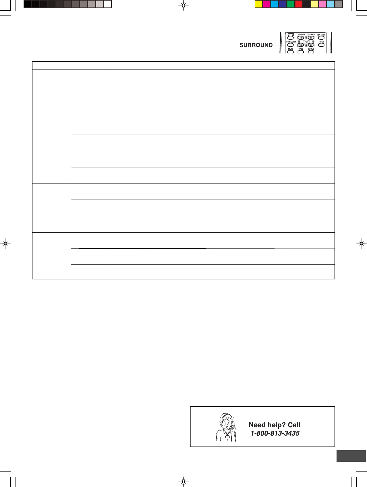
Selecting Surround Mode
Press [SURROUND] to select the surround mode.
Each time the button is pressed, the surround mode changes as follows:
5.1 AUTO v 5.1 SURR v 2.1ch v DIRECT v 5.1 AUTO…
FL display
The unit selects the surround mode automatically depending on the disc.
•If a DVD disc is encoded with Dolby Digital 5.1 channel, it is played back with Dolby Digital 5.1
channel surround sound.
Not all DVD discs are encoded with Dolby Digital 5.1 channel surround sound.
•If a DVD disc is encoded with Dolby Digital 2 channel or mono, it is played back with Dolby Pro
Logic mode. “sPL” appears briefly on the display.
•If a DVD disc is encoded with 2 channel Linear PCM (stereo), it is played back with Dolby Pro
Logic mode. “sPL” appears briefly on the display.
•Audio CDs are played back with Dolby Pro Logic mode.
• MP3/WMA discs are played back with Virtual 5.1 channel surround sound.
Notes:
•When using headphones, the surround mode does not change. If [BASS] or [SURROUND] is pressed, “-BASS-” or “-SURR-”
appears briefly on the display.
•DVD video discs with DTS may not work correctly. You can see the picture on the TV screen, but there is no sound.
In this case, press the AUDIO button repeatedly while holding the SHIFT button down to select Dolby Digital sound. (See page E28.)
•When receiving weak FM broadcasts, set the mode to “2.1ch”. The sound quality may improve.
5.1 SURR
5.1 AUTODVD/CD
AUX
FM TUNER
(Stereo)
Function Description
2.1ch
5.1 AUTO
5.1 SURR
2.1ch
Disc is played back with Virtual 5.1 channel surround sound.
The surround mode is set to 2.1 channel (Front left and right speakers, and Sub-woofer).
The surround mode is set to Virtual 5.1 channel surround sound.
FM TUNER
(Mono)
The surround mode is set to 2.1 channel (Front left and right speakers, and Sub-woofer).
Manufactured under license from Dolby Laboratories.
“Dolby”, “Pro Logic” and the double-D symbol are trademarks of Dolby Laboratories.
5.1 AUTO
5.1 SURR
Front left and right speakers, Center speaker, and Sub-woofer sound.
DIRECT Original audio signal from the disc
DIRECT Original audio signal
2.1ch The surround mode is set to 2.1 channel (Front left and right speakers, and Sub-woofer).
DIRECT Original audio signal
-E19-
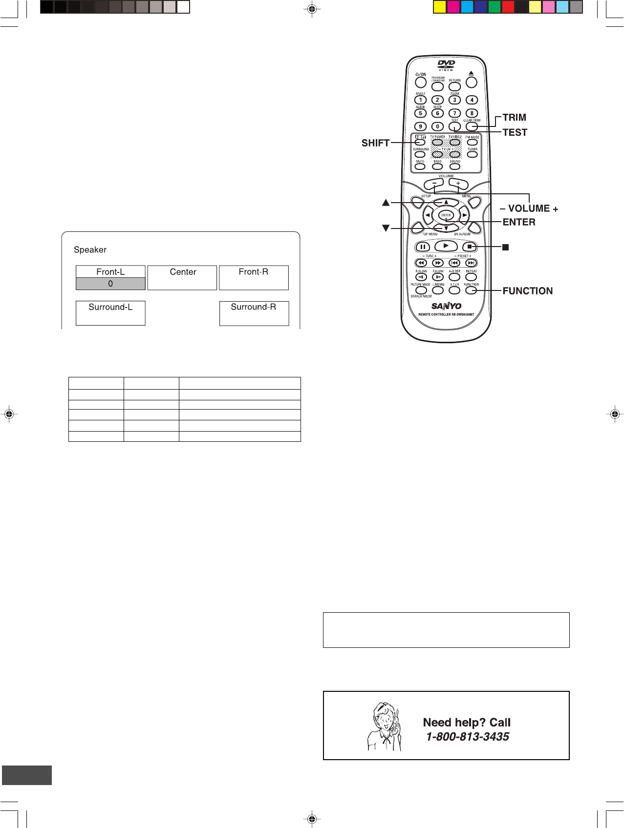
Adjusting the Speaker Volume Balance
This unit is set to the standard level before shipping from the
factory. You may not need any adjustment.
However, depending on the size of the room and the placement
of the speakers, you may benefit from a fine adjustment.
In this case, follow the steps below. Please use the remote
control when the test tone sounds.
Note:
Do not connect the headphones.
1. Press [FUNCTION] to select “DVD/CD”.
2. Press [n] to stop playback completely.
3. Press [TEST] on the remote control.
The “Speaker” screen appears on the TV screen.
“FNT-L 0” appears on the display.
The test tone will be heard from each speaker sequentially as
follows:
TV screen FL display Speaker
Front-L FNT-L 0 Front left speaker
Center CENT 0 Center speaker
Front-R FNT-R 0 Front right speaker
Surround-R SUR-R 0 Rear (surround right) speaker
Surround-L SUR-L 0 Rear (surround left) speaker
Note:
There are Surround left and right speakers in the rear
speaker.
4. Press [VOLUME] + or - until the test tone becomes a
comfortable level.
5. If the test tone level is not the same from each speaker, press
[p] or [o] to adjust it while the speaker is activated.
The level appears on the TV screen and display.
Front-L: “-10” ~ “0” appears.
Center: “-10” ~ “+10” appears.
Front-R: “-10” ~ “0” appears.
Surround-R: “-10” ~ “+10” appears.
Surround-L: “-10” ~ “+10” appears.
If necessary, repeat this step again.
6. Press [TEST] to turn the test tone off.
Note:
If no adjustments are made, the original display returns after
the test tone has cycled around 5 times.
Adjusting the Sub-woofer Level
Note:
Do not connect the headphones.
1. Press [TRIM] while holding [SHIFT] down.
“FNT-L 0” appears on the display.
Note: No test tone.
2. Press [ENTER] repeatedly to select “SUB.W 0”.
Note:
Each time the button is pressed, the display will show the
selected speaker and tone level.
3. Press [p] or [o] to adjust the level as desired.
SUB.W: “-10” ~ “+10” appears.
Note:
If another speaker is selected, the level can also be changed
as above.
4. Press [TRIM] while holding [SHIFT] down to turn it off.
Note:
If no adjustments are made, the original display returns after
approximately 10 seconds.
IMPORTANT INFORMATION:
Set the delay time for your center and surround speakers. See
“Setting Audio” on page E36.
-E20-
1
ALL
1
3
2
3
LB16:9
TM
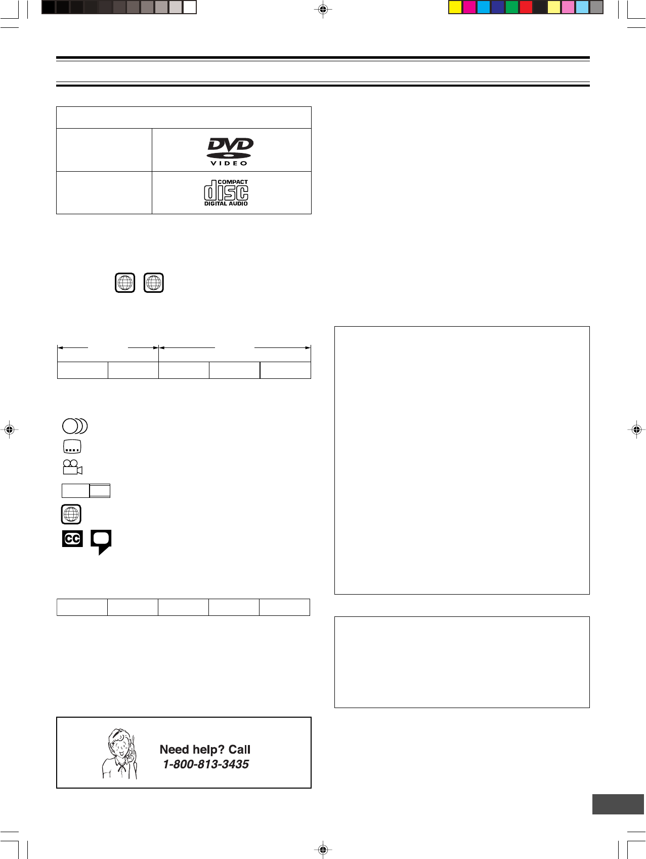
PLAYABLE DISCS
Disc type and logo mark
DVD-Video
The following types of discs can be played on this unit.
Audio CD
CAUTION:
•Only the above types of discs can be played on this unit.
DVD-ROM, CD-ROM, SVCD, CVD, VCD, etc. cannot be
played.
•This unit can play back the DVD-R that has recorded movie
data as well. However, some DVD-Rs cannot be played back
depending on the recording conditions.
•The DVD-R that has no movie data cannot be played back.
•The DVD-RW (Video mode) can be played back. However,
some DVD-RWs cannot be played back depending on the
recording conditions. The DVD-RW (VR mode) cannot be
played back.
•The DVD+R/+RW can be played back. However, some
DVD+R/+RWs cannot be played back depending on the
recording conditions.
•This unit is to be used exclusively with the NTSC color
system.
• For MP3/WMA CD, please see page E31.
•For Picture/JPEG CD, please see page E32.
Region Number
Region number (Regional restriction code) is built-in to the unit
and DVD video discs.
Region number “1” or “ALL” of DVD video discs can be used on
this unit.
DVD Video Disc
DVD video discs are divided into titles, and the titles are sub-
divided into chapters.
Title 1
Chapter 1 Chapter 2
Title 2
Chapter 1 Chapter 2 Chapter 3
There are the marks on some DVD video disc package.
Examples:
Multiple languages
Multi-language subtitles
Multi-angle
Multi-aspect
Region number
Closed caption
This product incorporates copyright protection technology that
is protected by method claims of certain U.S. patents and other
intellectual property rights owned by Macrovision Corporation
and other rights owners. Use of this copyright protection
technology must be authorized by Macrovision Corporation,
and is intended for home and other limited viewing uses only
unless otherwise authorized by Macrovision Corporation.
Reverse engineering or disassembly is prohibited.
Handling, Storing and Cleaning Discs
•Do not touch the disc door while it is moving.
•Never put anything except a 5-inch (12cm) or 3-inch (8cm)
DVD (or CD) into the disc compartment.
Foreign objects can damage the unit.
•Fingerprints and dust should be carefully wiped from the
signal surface of the disc (glossy side) with a soft cloth.
Wipe in a straight motion from the center to the outside of
the disc.
•Never use chemicals such as record cleaning sprays,
antistatic sprays or fluids, benzene or thinner to clean the
discs. These chemicals will permanently damage the plastic
surface of the disc.
•To remove a disc from its storage case, press down on the
center of the case and lift the disc out, holding it carefully by
the edges.
•Discs should be returned to their cases after use to protect
them from dust and scratches.
•To prevent warping the disc, do not expose it to direct
sunlight, high humidity or high temperatures for extended
periods of time.
•Do not apply paper or write anything on either side of the
disc. Sharp writing instruments, or the inks used in some
felt-tip pens, may damage the surfaces of the disc.
Audio CD Disc
Audio CD discs are divided into tracks.
Track 1 Track 2 Track 3 Track 4 Track 5
-E21-
VIDEO 1
Preparations
•Turn on the TV and select the video input source.
Refer to your TV’s owner manual.
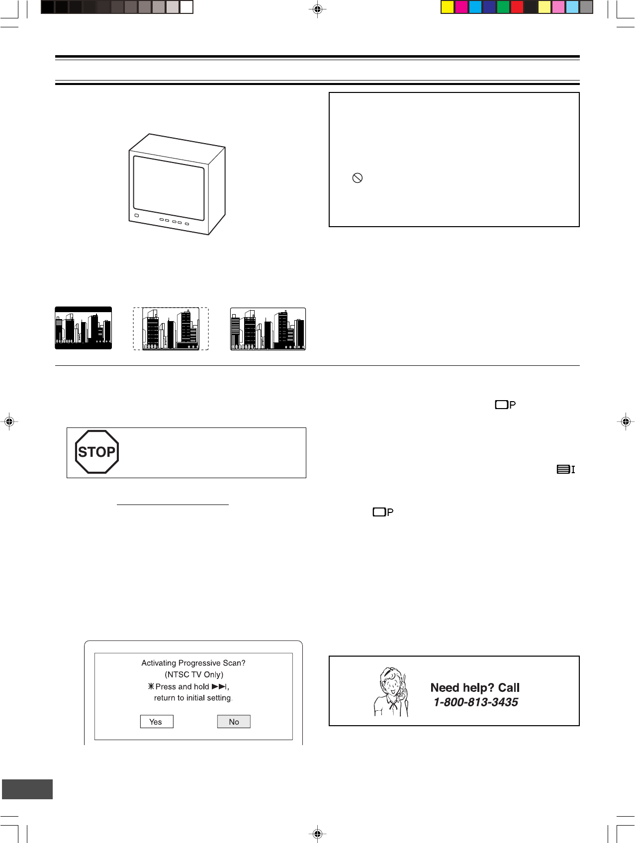
DISC PLAYBACK
•Select the playback picture size according to the aspect ratio
of the TV. (See “Setting Display” in “INITIAL SETTINGS” on
page E34.)
TV
4:3 LB
(Letterbox)
4:3 PS
(Panscan)
16:9
•When you use a TV with Progressive-scan capability and
connect it to the COMPONENT VIDEO OUT jacks of the
sub-woofer (See page E15), you must select the
PROGRESSIVE mode. (For more details, please refer to
your TV's owner manual.)
If you use a Conventional TV or non-
progressive-scan TV, skip this section.
1. Set the VIDEO OUT SELECT switch to the COMPONENT
position before turning the power on. (See page E15.)
2. Press [z/ON] to turn the power on.
3. Press [FUNCTION] to select “DVD/CD”.
4. Select “TV System: NTSC” and “Progressive: On” in
“Setting Display” (See pages E34 and E35.), and close
the setup screen.
5. In “NO DISC” mode, press and hold down [ e ] on the
remote control until the following message appears on
the TV screen.
Important Note:
•This instruction manual explains the basic instruction of
this unit using the remote control unit.
•Some DVD video discs have different functions that may
not be explained in this instruction manual. You may need
extra instructions. In this case, please follow the instructions
displayed on the TV screen or jacket or case of the disc.
•“ ” may appear on the TV screen during operation. This
icon means that the function is not available on the disc
now.
•For improvement, on-screen displays subject to change
without notice.
6. Press [b] to select “Yes”.
7. Press [ENTER].
The progressive mode is set. “ ” (Progressive)
appears briefly and “SANYO” logo screen returns.
Note:
If you do not want it, select “No”, then press [ENTER].
If you accidentally select it and switch the setting
back again, press and hold down [ee
ee
e] until “ ”
(INTERLACE) appears briefly on the TV screen.
Note:
In “ ” mode, the closed caption may not appear on
the TV screen.
-E22-
MENU
Play Movie
Languages & Audio Set-Up
Subtitles
Theatrical Trailers
Scene Selections
Basic Playback
When operation buttons are pressed, that operation is displayed
on the TV screen. The display disappears after several seconds.
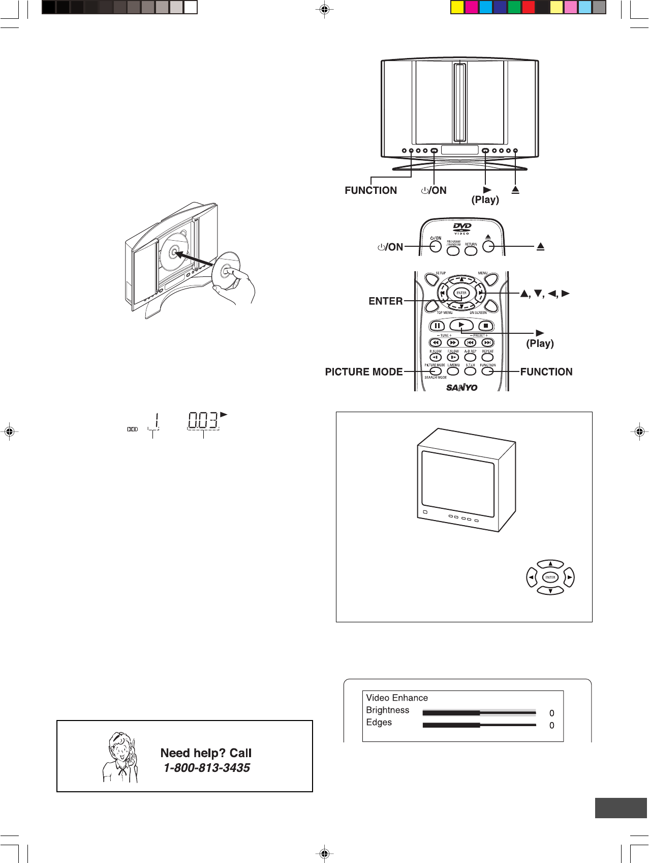
1. Press [z/ON] to turn the power on.
2. Press [FUNCTION] to select “DVD/CD”.
3. Press [q].
“OPEN” appears on the display and the disc door opens.
4. Place the disc (label facing toward you) on the disc turntable
until it clicks.
Label facing toward you
CAUTION:
Never touch the lens!
5. Press [q] to close the disc door.
•“CLOSE” ---> “READING” appears on the display.
•Playback starts automatically.
Example:
If a DVD disc menu screen appears on the TV screen...
TV
1. Press [o], [a], [p] or [b] (or the number buttons) to select the
desired menu.
2. Press [ENTER].
Playback of the selected menu starts.
Note:
For more details, please refer to the jacket or case of the disc.
Chapter number Elapsed playing time
Note:
Some discs may not start playback automatically. In such
case, press [a] (Play) to start playback.
CAUTION:
Do not touch the disc door while it is closing. This will
damage the inside of the unit and the disc.
Notes:
•In some discs, even if 4:3 PS is selected, the black bands
may remain on the screen.
•If the disc is loaded with the label side downward (and it is a
single sided disc), or if a badly scratched disc is loaded, “NO
DISC” (or “NO PLAY”) appears. If this occurs, load the disc
correctly or replace the disc.
Selecting Picture Mode
1. Press [PICTURE MODE]. “Video Enhance” screen appears.
2. Press [5] or [4] to select “Brightness” or “Edges”.
3. Press [a] or [b] to adjust the level as desired. Usually set “0”.
4. Press [PICTURE MODE] again to close the screen.
-E23-
Stopping Playback
•Press [n] once during playback. “Resume n” appears briefly
on the TV screen.
When you press [a] (Play), playback starts automatically
from the point where you stopped. “a” appears briefly on the
TV screen.
Note:
Some discs may not resume playback.
•Press [n] twice during playback. “n” appears briefly on the
TV screen and playback stops completely.
When you press [a] (Play), playback starts from the beginning
of the disc.
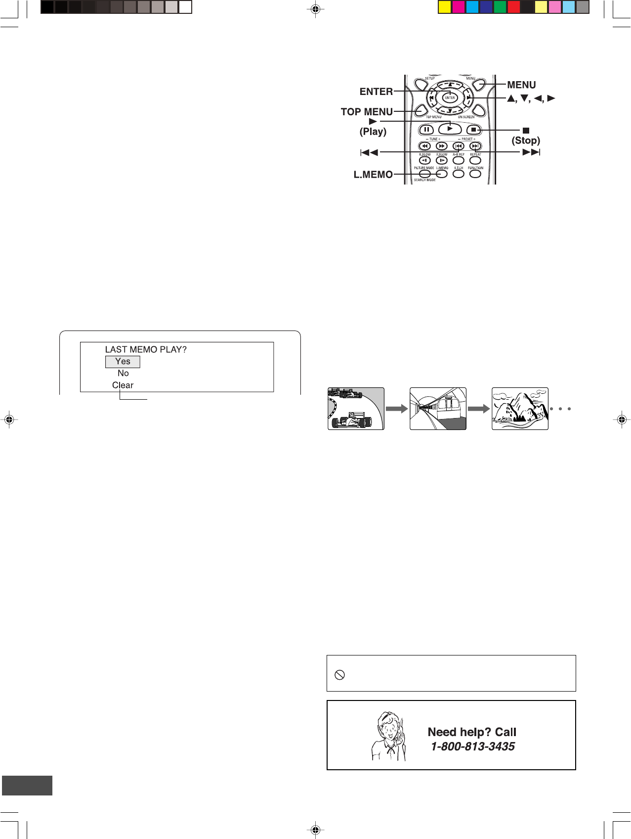
Continuing Playback from Where You Stopped
Watching (LAST MEMO PLAY), for DVD only
1. Press [L.MEMO] to stop playback.
“LAST MEMO n” appears briefly on the TV screen.
“LM STOP” appear on the display.
2. Remove the disc or turn off the power.
3. Load the disc (and press [a] (Play)), or turn on the power.
“LAST MEMO PLAY?” appears on the TV screen.
(The memory is released.)
4. Press [4] to select “Yes”.
5. Press [ENTER].
Playback resumes from the point where you stopped.
Notes:
•Point on up to 3 discs can be memorized.
•The Last Memo Play mode may not work correctly with some
discs.
Important Note:
“ ” may appear on the TV screen during operation. This icon
means that the function is not available on the disc now.
Selecting a DVD Menu
Notes:
•The operation may differ depending on the disc used.
•Selecting a menu may not be possible on some discs.
1. Press [MENU].
The main menu screen will appear.
Note:
Press [MENU] again to resume playback.
2. Press [4], [5], [b] or [a] (or the number buttons) to select the
desired menu.
3. Press [ENTER]
The selected menu playback starts.
Note:
If [RETURN] is pressed in some discs, it returns to the previous
menu screen.
Selecting a Top Menu [DVD]
Notes:
•The operation may differ depending on the disc used.
•Selecting a top menu may not be possible on some discs.
1. Press [TOP MENU].
The top menu will appear (if the disc contains a top menu).
2. Press [4], [5], [b] or [a] (or the number buttons) to select the
desired menu.
3. Press [ENTER].
The selected menu playback starts.
Chapter (Track) Skip
Skipping forward
Press [e] during playback to skip to the next chapter (or track).
“e” appears briefly on the TV screen.
A chapter (or track) is skipped each time the button is pressed.
Skipping backward
Press [f] during playback to skip back to the beginning of the
chapter (or track) currently played.
“f” appears briefly on the TV screen.
Press the button again immediately to skip back to the beginning
of the previous chapter (or track).
Note:
You can skip only through the chapters, not over the title on the
DVD disc.