SCANWAY TECHNOLOGY T102 WIFI module User Manual T102 DataSheet V1 0
SHENZHEN SCANWAY TECHNOLOGY CO.,LTD WIFI module T102 DataSheet V1 0
User manual
T102 DATASHEET
深圳市盛创威科技有限公司
1
Version 1.0
T102 Wi-Fi module V1.0
1. Product Overview
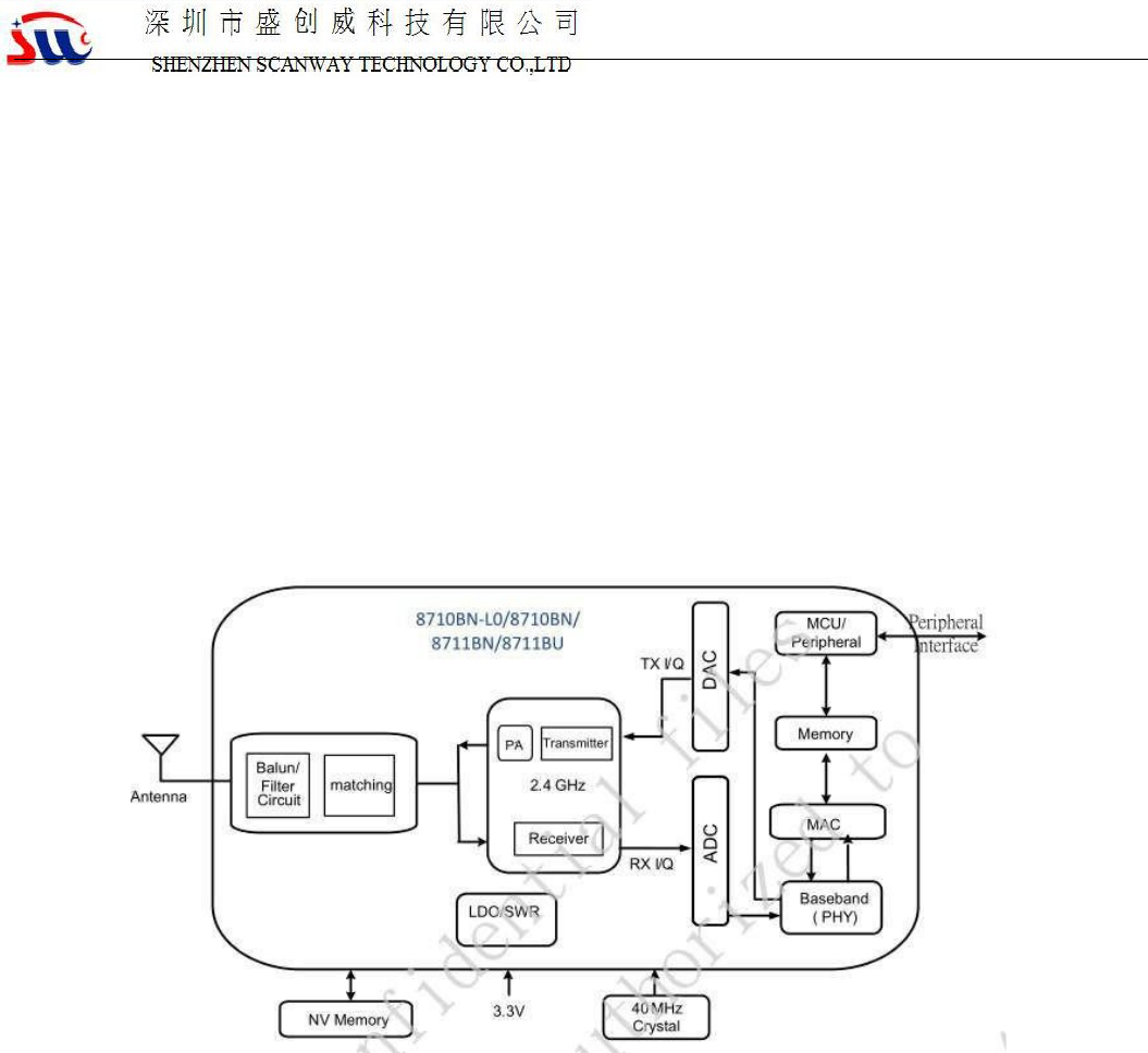
T102 is a low-power embedded Wi-Fi module developed by Shenzhen Shengchuangwei Technology
Co., Ltd. It consists of a highly integrated radio frequency chip RTL8710BN and a small number of
peripheral devices, built-in Wi-Fi network protocol stack and a wealth of library functions. The T102
embeds ARM-CM4 MCUs, 1Mbyte of flash memory, 256Kbytes of SRAM and a wealth of peripheral
resources.
The T102 runs the RTOS platform and integrates all Wi-Fi MAC and TCP/IP protocol libraries. Based
on these, users can develop embedded Wi-Fi products that meet their needs.
The functional schematic of the T102 is shown in Figure 1:
Figure 1 T102 functional schematic
1.1 Features
Built-in ARM_CM4 MCU, can double as application processor
Main frequency support 125MHz
Working voltage: 3.0V-3.6V
Peripherals: 9×GPIOs, 1×UART, 5×PWM
Wi-Fi connectivity
802.11 b/g/n
Channel 1-14@2.4GHz
Support WPA/WPA2 security mode
Output power of up to +16dBm in 802.11b mode
STA/AP/STA+AP working mode is supported.
Support SmartConfig features (including Android and IOS devices)
Onboard PCB antenna
Operating temperature: -20 ° C to 85 ° C
Test model: T102

T102 DATASHEET
深圳市盛创威科技有限公司
2
Version 1.0
1.2 Main application areas
Intelligent buildings
Smart home / home appliances
Smart socket, smart light
Industrial wireless control
Baby monitor
Webcam
Smart bus
This module will be used for all Main application areas
T102 DATASHEET
深圳市盛创威科技有限公司
3
Version 1.0
2.Module interface
Pin definition
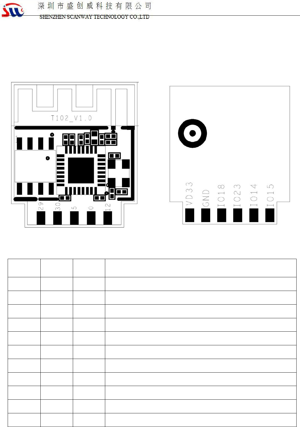
The T102 has 2 rows of 11 pins with a pin pitch of 2mm, as shown in Figure 1:
Figure 2 T102 front view Rear view
The interface pin definitions are shown in Table 1:
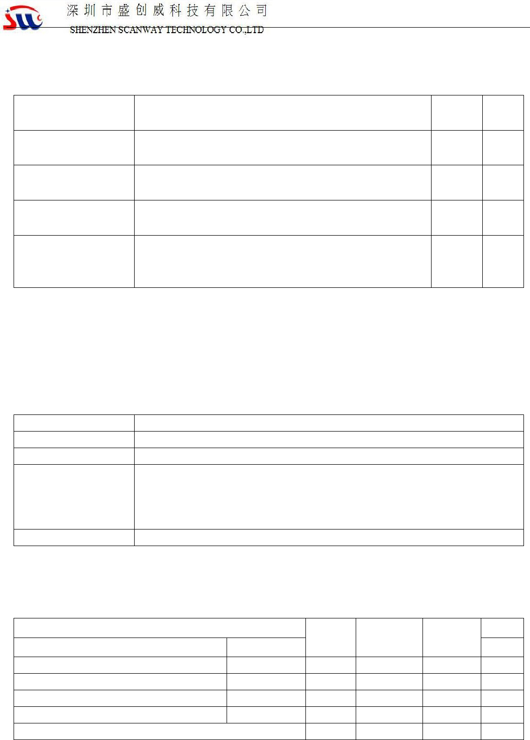
Table 1 T102 interface pinout description
Serial
number
symb
ol
IO
type
Features
1 VDD P Module power supply pin (3.3V)
3 GND P Power reference ground
5 A18 I/O GPIO_A18/UART0_RXD
7 A23 I/O GPIO_A23/UART0_TXD
9 A14 I/O GPIO_A14/PWM0
11 A15 I/O GPIO_A15/PWM1
2 A12 I/O GPIO_A12/PWM3
4 A0 I/O GPIO_A0/PWM2
6 A5 I/O GPIO_A5/PWM4
8 A30 I/O GPIO_A30/DEBUG_LOG_TX
10 A29 I/O GPIO_A29/DEBUG_LOG_RX
T102 DATASHEET
深圳市盛创威科技有限公司
4
Version 1.0
Description: P identifies the power supply pin, I/O represents the input and output pins, and AI represents the analog
input pin.
3. Electrical parameters
3.1 Absolute electrical parameters
Table 2 Absolute
parameters
param
eter
descr
iptio
n
Mini
mum
value
Maxi
mum
unit
Ts storage temperature -20 85 ℃
VCC Supply voltage -0.3 3.6 V
3.2 Working conditions
3 Normal working
conditions
parameter
description
Minimum value
Typical value
Maximum
unit
Ta
Operating
temperature
-
20
-
85
℃
VCC
Operating Voltage
3.0
3.3
3.6
V
V
OL
IO low output
-
-
VCC*0.1
V
V
OH
IO high output
VCC*0.8
-
VCC
V
I
max
IO drive current
-
-
16
mA
3.3 Wi-Fi transmission power consumption
Table 4 Power
consumption during TX
continuous transmission
symbol parameter Typical value unit
mode rate Transmit power
IRF 11b 11Mbps +16dBm 288 mA
IRF 11g 54Mbps +14dBm 258 mA
IRF 11n MCS7 +13dBm 251 mA
T102 DATASHEET
深圳市盛创威科技有限公司
5
Version 1.0
3.4 Wi-Fi receiving power consumption
Table 5 Power consumption of RX continuous reception
symbol parameter Typical value unit
mode rate
I
RF 11b 11Mbps 119 mA
IRF 11g 54Mbps 122 mA
IRF 11n MCS7 122 mA
T102 DATASHEET
深圳市盛创威科技有限公司
6
Version 1.0
3.4 Power consumption in working mode
Table 6 T102 operating current
Operating mode Working condition, Ta=25°C average
value
unit
Fast connection network
status
The module is in the state of fast connection network, and
the WI-FI indicator flashes quickly.
120 mA
Hot spot distribution
status
The module is in the hotspot distribution network, and the
WI-FI indicator flashes slowly.
122 mA
Network connection
status
The module is in a networked state and the Wi-
Fi indicator is
always on.
51 mA
Network disconnection
status (try networking)
The module is in the working state of disconnected network
(trying to connect to the network), and the Wi-Fi indicator is
always off.
116 mA
4 RF characteristics
4.1 Basic RF characteristics
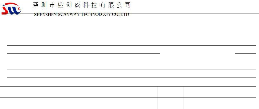
Table 7 Basic RF
characteristics
Parameter item
Detailed description
working frequency
2.412~2.484GHz
Wi
-Fi standard
IEEE 802.11b/g/n (channels 1
-14)
Data transfer rate
11b:1,2,5.5, 11 (Mbps)
11g:6,9,12,18,24,36,48,54(Mbps)
11n:BW20_MCS7 65Mbps
11n:BW40_MCS7 135Mbps
Antenna type
PCB antenna (default)
4.2 Wi-Fi output power
Table 8 TX continuous
transmission power
parameter Minimu
m value
Typical
value
Maximum
unit
mode rate dBm
RF average output power, 802.11b CCK Mode
11M 14 16 18 dBm
RF average output power, 802.11g OFDM Mode
54M 12 14 16 dBm
RF average output power, 802.11n OFDM Mode
BW20_MCS7 11 13 15 dBm
RF average output power, 802.11n OFDM Mode
BW40_MCS7
11
13 15 dBm
Frequency error -10 - 10 ppm
T102 DATASHEET
深圳市盛创威科技有限公司
7
Version 1.0
4.3 Wi-Fi receiving sensitivity
Table 9 RX sensitivity
parameter
Minimum
value
Typical
value
Maximum
unit
mode rate dBm
PER<8%, RX sensitivity, 802.11b CCK Mode
11M - -86 -80 dBm
PER<10%RX sensitivity, 802.11g OFDM Mode
54M - -89 -83 dBm
PER<10%RX sensitivity, 802.11nOFDM Mode BW20_MCS0 - -89 -83 dBm
PER<10%RX sensitivity, 802.11nOFDM Mode BW20_MCS7 - -71 -65 dBm
T102 DATASHEET
深圳市盛创威科技有限公司
8
Version 1.0
5 antenna information
5.1 Antenna type
Only the PCB onboard antenna is connected.
5.2 Reducing antenna interference
When using a PCB on-board antenna on a Wi‐Fi module, to ensure optimal Wi‐Fi performance, it is recommended
that the antenna portion of the module be at least 15 mm away from other metal parts.
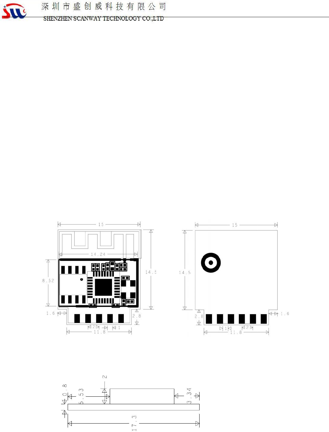
6. Packaging information and production guidance
6.1Mechanical dimensions
图 3 T102 Size
图 4 T102 Side view
T102 DATASHEET
深圳市盛创威科技有限公司
9
Version 1.0
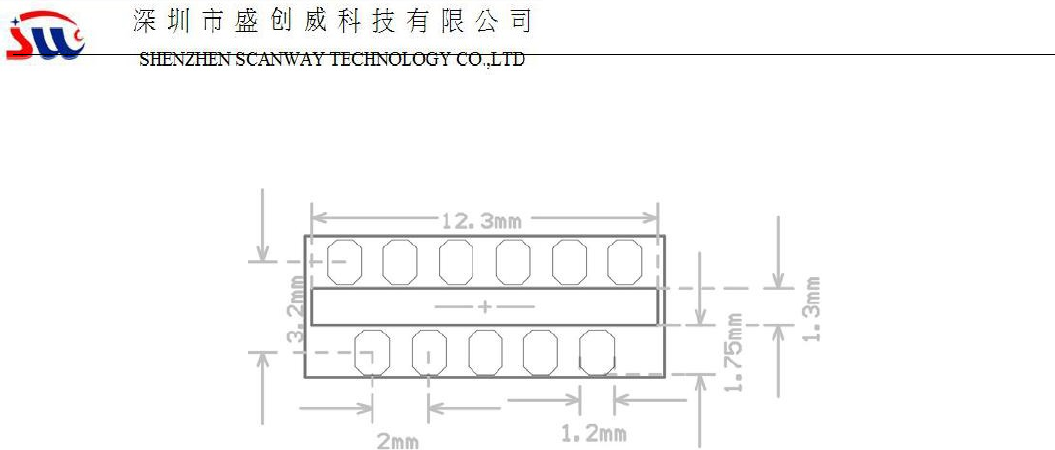
6.2 PCB Recommended Package
Figure 5 T102 PCB
package drawing
5.3 Production Guide
The factory module storage conditions are as follows:
1. The moisture-proof bag must be stored in an environment with a temperature <30 ° C and a humidity
<85% RH.
2. For dry-packed products, the shelf life should be 6 months from the date of sealing of the package.
Precautions
1. In the whole process of production, the operator of each station must wear an electrostatic ring.
2. When operating, prevent the module from getting wet or dirty.
The host will Satisfy Class I or Class Ⅱ permissive change based this module FCC ID.
If the FCC identification number is not visible when the module is installed inside the host, then
the outside of the device into which the module is installed must also display a label referring to
the enclosed module. This exterior label can use wording such as the following: “Contains
Transmitter Module Contains FCC ID:2ASKS-T102 or “Contains FCC ID:2ASKS-T102 .Any similar
wording that expresses the same meaning may be used.
20C