SCHNEIDER ELECTRIC FRANCE EASERGYHU250 Communication Gateway User Manual
SCHNEIDER ELECTRIC INDUSTRIES FRANCE Communication Gateway
User manual.pdf
HU250
MV electrical network management
Easergy T300 range
Control and communication unit
WARNING
RISK OF MATERIAL DAMAGE
bDo not expose the device to conditions exceeding the
electrical values specied in this document.
bThe device should be installed horizontally in an
electrical cabinet, in accordance with the local regulations in
force.
bThe product must be connected to the ground (DIN rail)
to ensure compliance with electromagnetic compatibility
(EMC) limits.
bStandby protection should be provided in accordance
with national and international cabling regulations.
bAn appropriate electrical disconnecting device must be
installed in the building in question.
bUse only the type of connector supplied as an accessory
for the HU250 module (product reference: EMS59010).
bCheck that the connections correspond to the
recommended cables before powering up the equipment.
bUse appropriate tools to perform cabling on the
connectors (suitable screwdriver, crimped end-pieces, etc.).
bStrip the wires appropriates (not excessively) before
connecting them to the connectors.
Failure to comply with these instructions can cause
material damage.
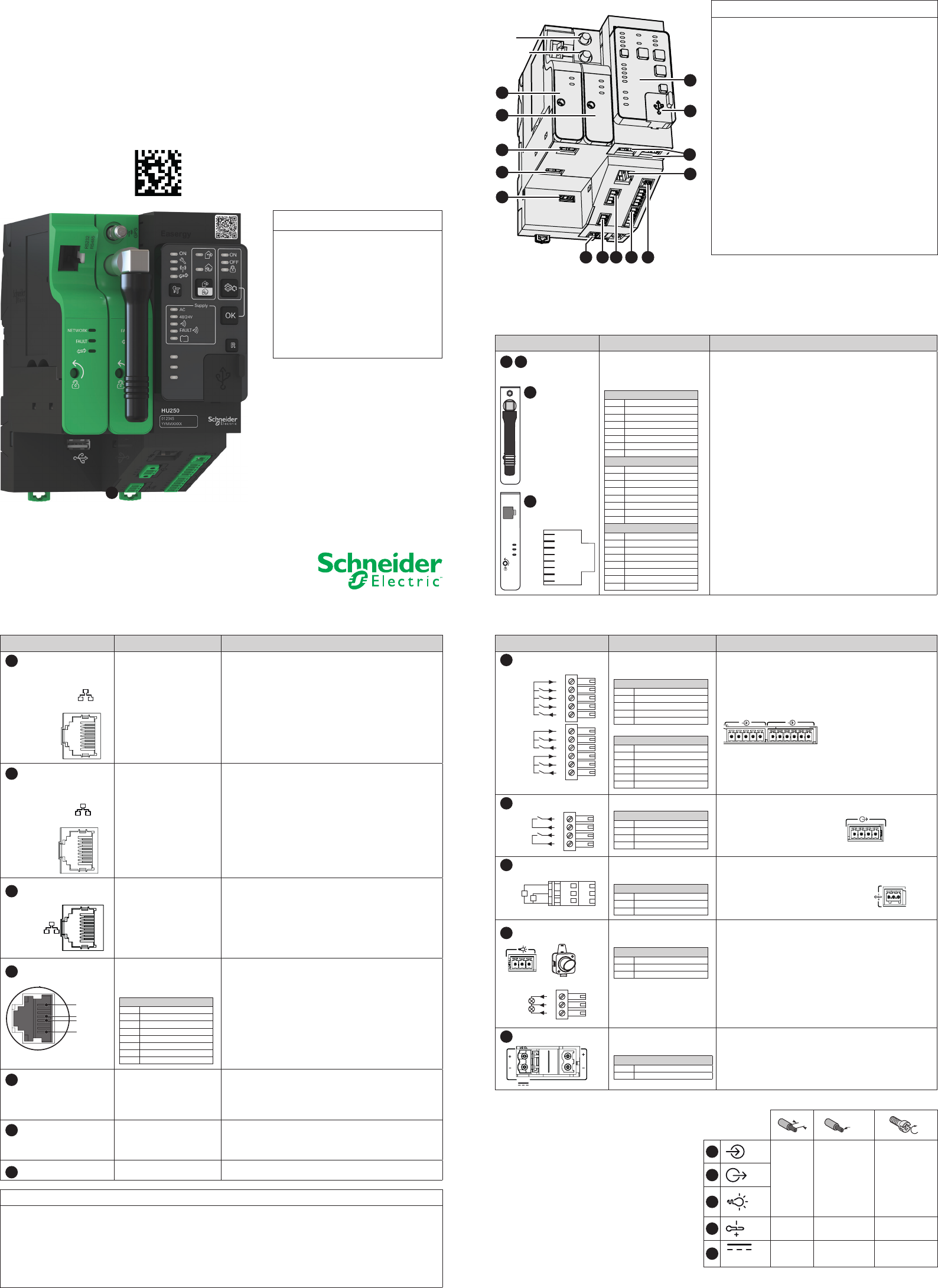
Description
The HU250 module of the Easergy T300 range is the communication gateway dedicated to remote control
applications for T300 units.
Port Characteristics Description
3 Local
communication
Ethernet port
10/100 Base-T RJ45
connector
Ethernet port used for the link to an external device
in the MV substation or for connection to a PC.
Isolation: 2kVAC
4 Remote
communication
Ethernet port
10/100 Base-T RJ45
connector
Ethernet port used for the remote link to the control
center, via a modem or router.
Isolation: 4kVAC
5 Double Ethernet
ports
LAN 1 and 2
10/100 Base-T RJ45
connectors
Double ports dedicated to internal communication
between T300 modules.
Isolation: 2kVAC
10 Ethernet jumpers (Ref: EMS59528) provide as
accessories allow the internal Ethernet connection
between the modules HU250, SC150 and LV150.
6 RS485 port
Flair 23DM
D0
Commo
n
D1
1
RJ45 connector capable
of including the following
connections:
RS485 (2-wire)
1
2
3
4 D1 (B)
5D0 (A)
6
7
8
Port dedicated to internal Modbus communication
with the Easergy PS50 power supply module or any
other device communicating in Modbus protocol
Speed: up to 38400 baud
Isolation: 2kVAC
7 WiFi port Dual-band concurrent
WiFi (2.4GHz/5GHz)
Secure WiFi port for local connection of a PC, tablet
or smartphone to:
bThe T300’s embedded Web server;
bThe Easergy Builder advanced conguration tool
8 Expert USB port Mini USB connector Mini USB port dedicated to equipment maintenance
(reserved for qualied personnel).
Requires the installation of a specic driver.
9 Host USB port B type USB connector Multi-purpose USB peripheral
Port Characteristics Description
10 Digital inputs Plug-in screw
connectors:
Digital inputs 1
1 Common (+24VDC)
2Digital input 1
3Digital input 2
4 Digital input 3
5Digital input 4
Digital inputs 2
1 Common (+24VDC)
2Voltage presence
3Door open
4 Common (+24VDC)
5Local
6Remote
8 digital inputs:
b4 unallocated digital inputs (for free use)
b4 dedicated digital inputs for:
vvoltage presence (e.g. via the PS50 module)
vconnection of a door open switch
4
3
2
1
Remote
Local
Door open
V present
6
5
3
2
1
DI1
DI2
DI3
DI4 5
4
11 Digital outputs
Plug-in screw connector:
Digital outputs
1 DO1
2DO1
3DO2
4DO2
2 dry-contact digital outputs for free use.
Breaking capacity: 2000VA
Max. voltage: 60VDC
Max. current: 2A
Isolation: 2kVAC
12 Analog inputs
Plug-in leaf-spring
connector:
PT100
1 In1
2In2
3 Réf
2 analog inputs for connection of PT100
temperature sensors
Measurement: -55°C to 250°C
(-67°F to 482°F)
Resolution: 1°C (1°F)
13 Indicator outputs Plug-in screw
connector:
Indicator lamps
1 Indicator 1
2Common +5V
3 Indicator 2
2 polarized indicator outputs for external indication
outside the MV substation. These indicators can be
assigned by conguration to fault detection
indication (directional indication).
Refer to the User Manual or the Expert Guide.
Voltage delivered: 5V
Max. current: 100 mA
Note: These outputs are polarized. Comply with the
direction of connection, + and -
123
FAULT
+3
Indicator
1+1
-2
Indicator
2
14 Power supply Plug-in screw
connectors:
Power supply
+ + Vdc (+12V to +48V)
- 0V
2 power supply connectors connected internally,
facilitating serial connections and allowing looping
of power supplies between the T300 modules.
(see Power Supply section).
Installation
Guide
3G/GSM
7
8
6
3
2
1
GPS
4
9
1210111314
5
DE53832.eps
1234
IMPORTANT NOTE
Only qualied personnel should carry out the
installation, operation, servicing and
maintenance of electrical equipment.
Schneider Electric accepts no liability regarding
any consequences of the use of this
documentation.
By qualied person is meant a technician who
is competent regarding the construction,
installation and operation of electrical
equipment and is trained in safety procedures,
and is therefore capable of detecting and
preventing the risks involved.
1
The HU250 includes the following components:
Port Characteristics Description
1 2
Communication
ports
RS232/RS485:
RJ45 connector including
the following connections:
RS232
1TXD
2RXD
3 CTS
4 DTR
5DSR
6RTS
7DCD
8 GND
RS485 (2-wire)
1
2
3
4 D1 (B)
5D0 (A)
6
7
8 GND
RS422 (4-wire)
1 RXD0 (A’)
2RXD1 (B’)
3
4 TXD1 (B)
5TXD0 (A)
6
7
8 GND (C/C’)
Customizable modem boxes including the following
modems:
bRS232/485: for the remote link to the control
center.
Speed: up to 38400 baud
Isolation: 2kVAC
b2G/3G: for the remote link to the control center.
b2G/3G + GPS: for the remote link with the control
center with GPS time synchronization.
Note: The 2G/3G or 2G/3G + GPS modem can only
be installed on port 1.
2G/3G
NETWORK
FAULT
RS232
RS485
8
7
6
5
4
3
2
1
1
2
PT100
1
2
3
PT100
12-48V
123
EXT
EXT
WARNING
RISK OF DAMAGE TO THE DEVICE
bUse appropriate tightening torques for tightening connector screws (tightening torque values provided in this
document).
bThe HU250 module must be powered by a power supply of the SELV/PELV type (e.g. the PS50 is of the SELV/ PELV
type).
bThe supply voltage of the HU250 module must not exceed 60VDC.
Failure to comply with the instruction may lead to risks of material damage.
61 2345 12345
3
4
D01 1
2
D02
Xmm2
N.m
10
7 mm
0.276 in
1.5 mm²
15 AWG
0.22-0.25 N.m
1.9-2.2 lb-in
11
13
12 8 mm
0.315 in
0.14-0.5 mm²
26-20 AWG -
14 7 mm
0.276 in
1.5 mm²
15 AWG
0.5-0.6 N.m
4.4-5.3 lb-in
12-48V
ETH1
ETH2
Under Promotion for Pilot Run
Printed on 2016/03/18
Power supply
The HU250 includes two connectors to connect the power supply. These two connectors are connected
together internally in the HU250. The fact of having two power supply connections can facilitate connection
between the modules. No strapping is necessary.
Moreover, this architecture allows loopback, thus offering the security of continuity of the power supply. For
any maintenance work, if one of the modules is removed from the loop, the other modules keep their power
supply during the replacement.
Connect the HU250 as shown in the following diagram in order to have the benet related to power supply
loopback.
As standards, specications and designs change from time to time,
always ask for conrmation of the information given in this publication.
Publication: Schneider Electric Telecontrol
Production: Schneider Electric Telecontrol
Printing: Schneider Electric Telecontrol
Schneider Electric Telecontrol
839 Chemin des Batterses - Z.I. Ouest
01700 St Maurice de Beynost
Tel.: +33 (0)4 78 55 13 13
Fax: +33 (0)4 78 55 50 00
http://www.schneider-electric.com
E-mail: telecontrol@schneider-electric.com
03-2016
Schneider Electric Industries SAS
Parameters setup
Installation of the HU250 module requires no parameters setup. This is performed during the commissioning/
conguration stages.
Refer to the User Manual and the Expert Guide for any further information.
Identication
The serial number of the HU250 is formed as follows: Year - Week - Work order
e.g. 15340265 (265th product manufactured, week 34 of the year 2015)
Grounding
The DIN rail on which the HU250 is installed must be grounded and of the metallic type. However, if the HU250 is
installed on a PS50 power supply module, grounding shall be performed on the power supply input of the PS50 and
not on the DIN rail. Refer to the Installation Guide of the PS50 power supply.
Installing the HU250 module on DIN rail
External dimensions of the HU250 enclosure
Installation
Installing the enclosure
The HU250 module is fastened to a DIN rail. No tool is needed for mounting.
Simply clip it in order to fasten it as shown below.
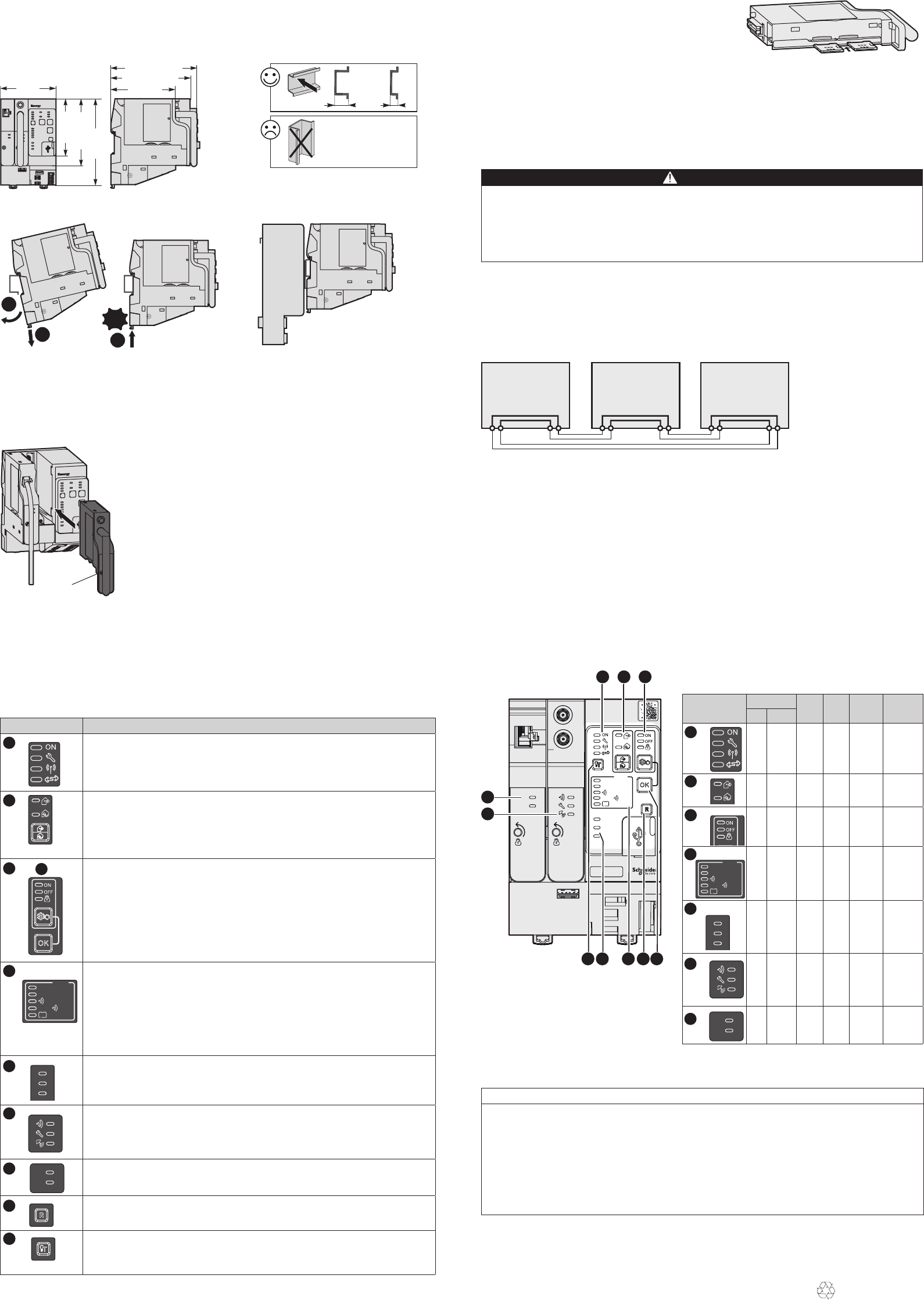
bInstall the modem box in the required slot on the HU250 (port 1 or
port 2 slot).
bPress the front panel to insert the rear panel connector in the HU250
(be careful not to over-force during insertion).
bTighten the screw on the front panel using a at or Phillips-head
screwdriver to fasten the modem box to the HU250.
To withdraw a modem box from its slot, perform the operation in reverse.
Note: When changing a modem box it is also necessary to have the
conguration changed by an expert using the Easergy Builder
conguration tool. To do so, refer to the Expert Guide.
GSM/3G modem
The 2G/3G modem allows a SIM card
card to be inserted in one of the two available SIM card slots,
without there being any difference at the operating level.
The GPS and GSM antenna connectors and the SIM cards are accessible on the front of the modem.
Mounting the GPS antenna:
bAttach the GPS antenna to the wall of the substation (preferably outside).
bConnect the antenna cable to the modem connector marked «GPS».
bInsert the SIM card(s) (preferably with HU250 switched off).
Note: The GSM/3G antenna requires no outside mounting. It is a short antenna connected to the modem itself.
This antenna is installed in factory.
Operation
Once the HU250 has been powered up, some indicator lamps on the front panel may be lit to indicate
certain operating states.
The buttons allow the user to perform actions.
These indications and actions are summarized in the table below:
Part Description of indications and actions
HU 250 states
1.1 HU 250 operating
1.2 Equipment fault
1.3 WIFI access operating (activated by Local mode)
1.4 T300 modules communication fault
Local/Remote
2.1 Local position: All remote controls are locked
2.2 Remote position: All local controls on switches via the SC150 module are locked (via the front
panel and WIFI).
2.3 Push button that can be used to change Local/Remote state
Note: Switching to local mode activates WIFI access
Automatic control states and checks
3.1 Automatic control enabled
3.2 Automatic control disabled
3.3 Automatic control locked
3.4 Automatic control change-of-state button (ON/OFF).
8.1 Change-of-state enabling button. The two buttons, change of state and enabling, must be
pressed simultaneously for the change of state to take place. This change is performed
simultaneously on all the T300 modules using automatic control functions.
Note: Change of state of the automatic control system by means of the buttons is possible only in
Local mode.
Power supply
4.1 Mains power supply operating
4.2 48V/24V motor pack power supply operating
4.3 Transmission equipment power supply operating
4.4 Over consumption on Transmission equipment power supply
4.5 Battery fault
Note: These states correspond to information retransmitted by the PS50 module via Modbus
communication between modules. When another type of power supply module is used, these
indicators can be customized by conguration via the Expert Easergy Builder tool.
Customizable indicator lamps
5.1;5.2;5.3 3 unassigned indicator lamps congurable for indication of customized states.
Note: Customization of these indicators is performed via the Easergy Builder conguration tool.
Refer to the User Manual or the Expert Guide.
3G/GPS modem box indicator lamps
6.1 Indicator of activity on the GSM/3G network. This indicator ashes at the pace of data
interchange (TX/RX).
6.2 Modem fault indicator lamp: lights for a SIM card fault or for any low level of GSM/3G reception.
6.3 GPS signal reception status indicator.
RS232-RS485 modem box indicator
7.1 TX: RS232/RS485 data transmission indicator lamp
7.2 RX: RS232/RS485 data reception indicator lamp.
Reset
9.1 Reset button reinitializing all fault indications on all the SC150 modules and automatic control
locking.
Indicator test
10.1 Indicator test button for forced setting of lighting of all indicator lamps on the front panel of
the T300 modules and the external indicator lamp. Makes it possible to detect any anomaly
concerning the indicator lamps.
Note: Refer to the table opposite for the meaning of the ashing states and the various possible colors for
indicator lamps. Some indicators can be customized by conguration.
Note: The indications in bold letters correspond to normal
operation (rst power up without the existence of a fault).
Indicator state
Flashing Steady
red
Steady
green
Steady
orange
Extinguished
Red Green
Boot
-
-
-
-
-
-
-
Fault
Fault
Fault
Fault
OK
-
OK
-
Com fault
-
OK
-
-
OK
-
OK
-
-
-
-
-
Local
Remote
-
-
-
Local
Remote
-
-
-
-
-
-
-
OFF
-
ON
-
-
-
-
Locked
OFF
ON
Non-locked
-
-
-
-
-
-
-
-
-
-
AC OFF
Fault
Fault
Fault
Fault
AC ON
OK
OK
-
OK
-
-
-
-
-
-
-
-
OK
-
-
-
-
-
-
-
-
-
-
-
-
-
ON
ON
ON
OFF
OFF
OFF
-
-
-
Activity
-
Active and
sync
-
Fault
-
-
-
No sync
-
-
-
Inactivity
OK
Deactivated
-
-
Emission
Reception
-
-
-
-
-
-
Inactivity
Inactivity
(1) Indicators customizable by conguration. Only default values shown.
Meaning of indications for each color or
indicator lamp state.
93.4 mm
3.78 in
108.5 mm
4.27 in
140 mm
5.51 in
129 mm / 5.08 in
140 mm / 5.51 in
90 mm
3.54 in 104.5 mm
5.53 in
DE53831.eps
Made in France
15 mm
0.59 in
7 mm
0.28 in
DE53833.eps
DE53834.eps
Easergy
AC
48/24V
Supply
HU250
012345
YYMMXXXX
3G-GPS
TX
RX
RS232-RS485
1 2 3
4510 9 8
6
7FAULT
1.1
1.2
1.3
1.4
2.1
2.2
2.3
3.1
3.2
3.3
3.4
8.1
AC
48/24V
Supply
4.1
4.2
4.3
4.4
4.5
FAULT
5.1
5.2
5.3
DE53835.eps
HU250
12V/48V
SC150
12V/48V
PS50
12V/48V
+- +-+-+-+
-+
-
DE53836.eps
Installation of a modem box
Each modem box can be installed or interchanged easily and quickly in the HU250. The modem box is installed
in factory, but if necessary it is possible to dismount it and replace it with another type of modem. To install a
modem box:
DE53837.eps
DE53860.eps
2
1
Click!
3
1
38
4
2
5
7
1
2
3
4
5
6
9
6.1
6.2
6.3
7.1
7.2
TX
RX
9.1
10.1
et AC
48/24V
Supply
4.1
4.2
4.3
4.4
4.5
FAULT
5.1
5.2
5.3
7
6
6.1
6.2
6.3
7.1
7.2
TX
RX
1.1
1.2
1.3
1.4
2.1
2.2
2.3
3.1
3.2
3.3
3.4
8.1
(1)
10
DE53845.eps
Installing the HU250 module on a PS50 enclosure
DANGER
RISK OF BURNING, ELECTRIC SHOCK, EXPLOSION OR ELECTRIC ARC
bWear your personal protective equipment (PPE) and comply with the safety procedures. Refer to the local installation
standards in force.
bSwitch off the electric power supply of the HU250 and of all the devices to which the HU250 is connected before any
handling or replacement operation.
bUse a power off check to make sure that the device is properly switched off.
Failure to comply with these instructions may cause severe bodily injuries or death.
This document was printed on
environmentally friendly paper
Modem box
mounting
screw
NHA77925-02
IMPORTANT NOTE
Easergy HU250, FCC ID : 2AHHK-EASERGYHU250
Easergy GSM/3G modem box contains FCC ID : QIPPHS8-P
Caution: the user that changes or modications not expressly approved by the party responsible for compliance could void the user’s authority to operate the equipment.
NOTE: This equipment has been tested and found to comply with the limits for a Class B digital device, pursuant to part 15 of the FCC Rules. These limits are designed to provide
reasonable protection against harmful interference in a residential installation. This equipment generates, uses and can radiate radio frequency energy and, if not installed and used in
accordance with the instruction, may cause harmful interference to radio communications. However, there is no guarantee that interference will not occur in a particular installation. If this
equipment does cause harmful interference to radio or television reception which can be determined by turning the equipment off and on, the user is encouraged to try to correct
interference by one or more of the following measures:
- Reorient or relocate the receiving antenna.
- Increase the separation between the equipment and receiver.
- Connect the equipment into an outlet on circuit different from that to which the receiver is connected.
- Consult the dealer or an experienced radio/TV technician for help.
This device complies with FCC RF radiation exposure limits set forth for general population. This device must be installed to provide a separation distance of at least 20cm from all
persons and must not be co-located or operating in conjunction with any other antenna or transmitter.
Under Promotion for Pilot Run
Printed on 2016/03/18