SCHNEIDER ELECTRIC FRANCE EASERGYLV150 Easergy LV150 Low voltage Power meter User Manual
SCHNEIDER ELECTRIC INDUSTRIES FRANCE Easergy LV150 Low voltage Power meter
User manual.pdf
LV150-VT adapter is the interface between the Low Voltage
sensors and the LV150.
An Ethernet RJ45 cable connecting the VT adapter and the
LV150 can be supplied as accessory.
Refer to the LV150-VT adapter Installation Guide (ref:
NT00393-xx) to have more information about the installation
and connection of the LV150-VT adapter.
Xmm2
N.m
28 mm
0.315 in
0.14-0.5 mm²
26-20 AWG -
37 mm
0.276 in
0.2-2.5 mm²
24-13 AWG
0.5-0.6 N.m
4.4-5.3 lb-in
61-2.5 mm²
17 AWG
0.5-0.6 N.m
4.4-5.3 lb-in
12-48 V
140 mm
5.51 in
45 mm
1.77 in 129 mm / 5.08 in
77.5 mm
3.05 in
140 mm / 5.51 in
LV150
MV electrical network management
Easergy T300 range
Low Voltage Power monitoring unit
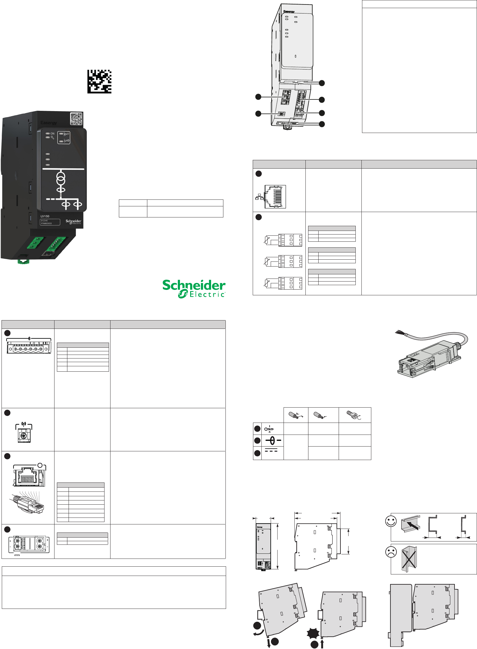
The LV150 is formed of the following components:
Port Characteristics Description
1
Double Ethernet
ports LAN 1 and 2
10/100 base-T RJ45
connector
Double ports dedicated to internal communication
between Easergy T300 modules or for connecting a
PC. Isolation: 2 kVAC
10 Ethernet jumpers (Ref: EMS59528) provide as
accessories allow the internal Ethernet connection
between the modules HU250, SC150 and LV150.
2 Analog inputs
Plug-in leaf-spring
connectors:
PT100 #1
1 In1
2 In2
3 Ref
PT100 #2
1 In1
2 In2
3 Ref
PT100 #3
1 In1
2 In2
3 Ref
3 analog inputs for connection of 3 wire PT100
temperature sensors.
Measurement : -55 to 250°C (-67°F to 482°F)
Resolution : 1°C (1°F)
Description
The LV150 module of T300 Easergy range is the Low Voltage measurement and transformer monitoring
unit.
Port Characteristics Description
3 Current inputs 6-pin plug-in screw
connector:
CTs inputs
1
Phase current 1
2
Phase current 2
3
Phase current 3
4
Phase current common
5
Neutral current common
6
Neutral current
For the details of the
connection, see chapter
"Connecting CTs"
4 inputs for connecting CTs:
b3 phase CTs,
b1 core for Neutral measurement.
Allows the following types of setup:
b3 phase CTs
b3 phase CTs + 1 core for Neutral measurement
Use a type of toroid with a primary / secondary ratio
that matches the following settings congurable in
the product:
bPrimary: 50 to 3000 A
bSecondary: 1 or 5 A
Zigbee antenna Snap-in connector bConnection of a Zigbee antenna for wireless radio
communication with current sensors (CTs).
(This communication is not operational at this time
and is reserved for future use).
Voltage inputs Connecting cable with
the voltage sensor
including an RJ45
connector on the LV150
side.
Voltage inputs
1Ph2 voltage (-)
2Ph2 voltage (+)
3Neutral voltage (+)
4Ph1 voltage (-)
5Ph1 voltage (+)
6Neutral voltage (-)
7Ph3 voltage (+)
8Ph3 voltage (-)
Connecting cable LV150 - Voltage sensor adapter
can be supplied as an accessory.
The wiring of the RJ45 connector on the LV150 side
is given solely for information.
This connecting cable is supplied for the following
adapter:
bLV150-VT adapter - 10 KV/1 sec (6 KV/1 mn)
insulation - ref EMS59574.
Power supply
Plug-in screw connectors:
Power supply
++VDC (+12 V to +48 V)
- 0V
2 power supply connectors connected internally,
facilitating serial connections and allowing looping of
power supplies between the T300 modules. (see Power
Supply section).
Installation
Guide
DM105352.ai
Installing the LV150 module on DIN rail
External dimensions of the LV150 enclosure
DM105356.eps
15 mm
0.59 in
7 mm
0.28 in
2
1
Click!
3
123456
12-48V
DM105357.eps
DE53833.eps
U
8 7 6 5 4 3 2 1
Installing the LV150 module on a PS50 enclosure
DM105358.eps
NOTICE
HAZARD OF INCORRECT CURRENT MEASUREMENTS
bDo not expose the device to conditions exceeding the
electrical values specied in this document.
bThe device should be installed vertically in an electrical
cabinet, in accordance with the local regulations in force.
bThe product must be connected to the ground (DIN rail)
to help ensure compliance with electromagnetic
compatibility (EMC) limits.
bStandby protection should be provided in accordance with
national and international cabling regulations.
bAn appropriate electrical disconnecting device must be
installed in the building in question.
bUse only the type of connector supplied as an accessory
for the LV150 module (product reference: EMS59220).
bCheck that the connections correspond to the recommended
cables before powering up the equipment.
bUse appropriate tools to perform cabling on the
connectors (suitable screwdriver, crimped end-pieces, etc.).
bStrip the wires appropriately (not excessively) before
connecting them to the connectors (see the
recommandations in this document).
Failure to follow these instructions can result in
equipment damage.
NOTE
Electrical equipment should be installed, operated, serviced,
and maintained only by qualied personnel. No
responsibility is assumed by Schneider Electric for any
consequences arising out of the use of this material.
A qualied person is one who has skills and knowledge
related to the construction, installation, and operation of
electrical equipment and has received safety training to
recognize and avoid the hazards involved.
NOTICE
HAZARD OF TERMINAL DAMAGE OR INCORRECT POWER SUPPLY
bUse appropriate tightening torques for tightening connector screws (tightening torque values provided in this document).
bThe LV150 module must be powered by a power supply of the SELV/PELV type (e.g. the PS50 module).
bThe supply voltage of the LV150 module must not exceed 57.6 VDC.
Failure to follow these instructions can result in equipment damage.
Part number Designation
EMS59300 Easergy LV150-Low Voltage Power
monitoring
DM105355.ai
PT100
1
2
3
2
45
3
1
6
PT100
1
2
3
PT100
1
2
3
#1
#3
#2
4
5
6
Recommendation for lengths of cable less than 2 meters
VT adapter for LV150
Installation
Installing the enclosure
The LV150 module is fastened to a DIN rail. No tool is needed for mounting.
Simply clip it in order to fasten it as shown below.
NHA9257502
Cabling
NHA92575-02
As standards, specications and designs change from time to time,
always ask for conrmation of the information given in this publication.
Publication : Schneider Electric
Production : Schneider Electric
Printing : Schneider Electric
This document was printed on
environmentally friendly paper
35 rue Joseph Monier
92500 Rueil Malmaison - France
Phone: +33 (0)1 41 29 70 00
www.schneider-electric.com
© 2017 Schneider Electric. All Rights
Reserved.
07-2017
Schneider Electric
Parameters setup
Installation of the LV150 module requires no parameters setup. This is performed during the
commissioning/conguration stages
.
Refer to the User Manual and the Quick Start manual for any further information.
Identication
The serial number of the LV150 is formed as follows: Year - Week - Work order, e.g. 16340265 (265th
product manufactured, week 34 of the year 2016)
Grounding
The LV150 module must be connected to the ground:
bEither via the mounting DIN rail. The DIN rail helps ensure electrical continuity (preferably use a DIN rail in
304L stainless steel to withstand the climatic conditions).
bEither by means of an eye lug and a M4 screw (max. Length 10 mm), screwed in the threaded hole at the
back of the LV150 housing (see diagram below). Use a green/yellow wire of length 300 mm maximum (11.81
in) and 4 mm² section (11 AWG) for the connection between the eye lug and the ground.
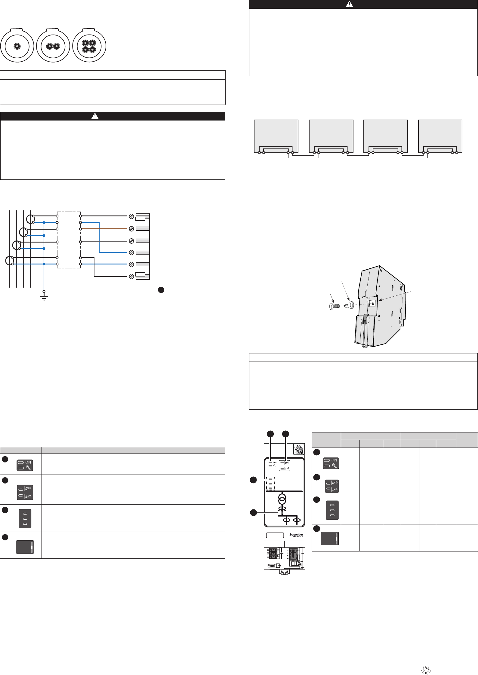
Operation
Once the LV150 has been powered up, some indicator lamps on the front panel may be lit to indicate certain
operating states.
These indications are summarized in the table below:
Part Description of indications and actions
LV150 states:
1.1 LV150 operating, communication status with the HU250
1.2
Equipment status (potential software issue, potential hardware issue, potential
conguration issue).
Not used
Not used
Voltage presence
4.1 Red: power on 3 phases
Extinguished: Invalid measure or power o on 3 phases
Orange: power on or o on at least one of the phases
Note: The indications in bold letters correspond to normal operation (rst power up
without existence of a potential issue indication).The voltage presence states cannot
be determined for normal operation, because that depends on the state of the
network.
Indicator state
Flashing Steady
Unlit
Red Green Orange Red Green Orange
Start-up
-
-
-
-
-
Fault
Major fault
OK
-
Com OFF
Minor fault
-
OK
- - -
ON
(3 ph.)
-
ON
(1 or
2 ph.)
Invalid or
OFF
(3 ph.)
Meaning of indicator colors and states
Made in France
Installing CTs
The setup concerns a 3 split-core phase CTs or 3 split-core phase CTs + neutral CT.
The cables must be centered as far as possible inside the toroid to help ensure the accuracy of the
measurement.
NOTICE
HAZARD OF INCORRECT CURRENT MEASUREMENT
bPay attention to the mounting direction of the CTs. It must not have an impact on the current measurement.
Failure to follow these instructions can result in equipment damage.
PS50
12V/48V
HU250
12V/48V
SC150
12V/48V
+- +-+-+-+-+-
LV150
12V/48V
+- +-
1.1
1.2
1
3
4
2
3.1
3.2
3.3
4.1
DM105362.eps
Easergy
LV150
012345
YYMMXXXX
12
4
3
1
2
3
4
1.1
1.2
3.1
3.2
3.3
4.1
DANGER
HAZARD OF ELECTRIC SHOCK, EXPLOSION, OR ARC FLASH
bWear your personal protective equipment (PPE) and comply with the safe electrical work practices. See NFPA 70E in
the USA or applicable local standards.
bOnly qualied person should install this equipment. Such work should be performed only after reading this entire set of
instructions.
bSwitch o the electric power supply of the LV150 and of all the devices to which the LV150 is connected before any
handling or replacement operation.
bAlways use a properly rated voltage sensing device to conrm that all power is o.
bDo not connect VT adapter directly to the LV sensors. Always use fuse and disconnect switch (maximum voltage
allowable on the VT adapter inputs : 10 VAC).
bNever short the secondary of a Voltage Transformer (VT).
Failure to follow these instructions will result in death or serious injury.
DM105361.eps
DM105366.eps
DANGER
HAZARD OF ELECTRIC SHOCK, EXPLOSION, OR ARC FLASH
bThe current sensors used for measuring must be 1 A or 5 A secondary with security factor limiting the current to 100 A
secondary -1 s (according to standard 61869-2).
bThe toroids must be short-circuited at the secondary when they are disconnected from the LV150 (eg during a
maintenance operation). To do this, use a shorting block.
bThe low-voltage insulation of the Easergy CTs means they can only be used on insulated cables.
bAlways use grounded external CTs for current inputs.
bEnsure the LV Network is turned o before to install the CTs on the LV cable and making the CTs connections to the
LV150.
Failure to follow these instructions will result in death or serious injury.
2.1
2.2
2.1
2.2
Power supply
The LV150 includes two connectors to connect the power supply. These two connectors are connected together
internally in the LV150. Having two power supply connections can facilitate connection between the modules. No
strapping is necessary.
Connect the LV150 as shown in the following diagram in order to have the benet related to power supply loopback
.
Connecting CTs
Com I 4
Com N 5
I3 3
I2 2
I1 1
L1
L2L3
N
N 6
S1
S2
S1
S2
S1
S2
S1
S2
Connector Current inputs 3
Not used
Not used
DM105369.ai
NOTICE
HAZARD OF INCORRECT CURRENT MEASUREMENTS
bThe DIN rail on which the LV150 is installed (if the LV150 is grounded by the DIN rail) must be grounded and of metallic
type and must comply with electrical continuity in all climatic conditions.
bIf the LV150 is installed on a PS50 power supply module, the grounding of the module is done via the PS50's DIN rail,
which must be grounded via a dedicated terminal near the PS50 power input connector. Refer to the Installation Guide of
the PS50 power supply.
Failure to follow these instructions can result in equipment damage.
Shorting
block
Eye lug
M4 screw Ground connection
terminal
DM105373.ai