SCR Engineers LDBUMODULE LD module User Manual SCR One
SCR Engineers Ltd. LD module SCR One
manual

SCR
LD Module
SPECIFICATIONS
[CONFIDENTIAL]
Meir D.
Version 0.1

P a g e 2
Version History:
0.10
Initial version
Contents
1 Global system specifications ........................................................................................... 4
Target market .................................................................................................................... 4
11 System components ................................................................................................ 4
1.2 TAG/IDU/BU communication overview .................................................................. 5
2 LD Module of BU-500 ................................................................................................. 6
2.1 BU-500 Units contains Internal Antenna .................................................................. 6
2.2 LD Module Options ................................................................................................ 7
2.3 Block diagram ........................................................................................................ 8
3 BU-500 Installation ........................................................................................................ 9

P a g e 3
The FCC Wants You to know
NOTE: This equipment has been tested and found to comply with the limits for a Class B digital
device, pursuant to part 15 of the FCC Rules. These limits are designed to provide reasonable
protection against harmful interference in a residential installation. This equipment generates, uses
and can radiate radio frequency energy and, if not installed and used in accordance with the
instructions, may cause harmful interference to radio communications. However, there is no
guarantee that interference will not occur in a particular installation. If this equipment does cause
harmful interference to radio or television reception, which can be determined by turning the
equipment off and on, the user is encouraged to try to correct the interference by one or more of the
following measures:
-Reorient or relocate the receiving antenna.
-Increase the separation between the equipment and receiver.
-Connect the equipment into an outlet on a circuit different from that to which the receiver is
connected.
-Consult the dealer or an experienced radio/TV technician for help.
FCC Warning
Changes or modifications to this equipment not expressly approved by the party responsible for
compliance (SCR Engineers Ltd.) could void the user’s authority to operate the equipment
LD Module FCC ID: AMULDBUMODULE
Manufacturer: SCR Engineers Ltd.
This device complies with Part 15 of the FCC Rules.
Operation is subject to the following two conditions:
(1) This device may not cause harmful interference, and
(2) this device must accept any interference received, including
interference that may cause undesired operation.
P a g e 4
1 Global system specifications
All units are for outdoor use, required Radio regulations according to target market &
Low voltage 24VDC regulation (except for tags which powered by internal battery).
Target market
Europe (EU), Swiss, Norway
USA, Canada
Eastern/North Europe (Belarus , Ukraine, Baltic states & All former Soviet
union republic)
South/Center America (Brazil, Argentina, Chile, Columbia, Peru, Ecuador,
Mexico)
China
Japan
Vietnam
South Korea
India
New Zealand
Australia
South Africa
Turkey
Israel
1.1 System components
LD Module – RF module of BU-500
BU-500 – LD Base unit, with 10BASE‑T/100BASE-TX Ethernet network
interface.
H-TAG-LD – Activity based tag with RF transceiver & IRDA receiver.
HR-TAG-LD – Activity & Rumination based tag with RF transceiver & IRDA
receiver.
IDU530 – Tag identification unit with CAN-Bus network interface, IRDA
transmitter & 2.4GhZ Receiver ONLY.
IDU510 – Tag identification unit with SCR C.L. network interface, IRDA
transmitter & 2.4GhZ Receiver ONLY.
BU-500E – LD Base unit, with RS-485 network interface.
P a g e 5
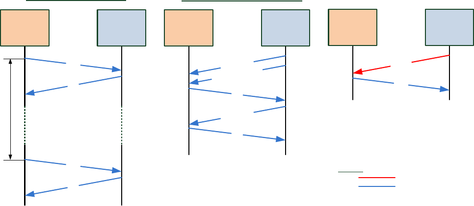
1.2 TAG/IDU/BU communication overview
Tag
Tag initiate sending data
BU500
Data
Ack
Tag
BU initiate sending messages
BU500
Ack
Message 1
Data
Ack
20 minutes
Message 1 retry*
Message 2
Ack
Tag IDU
Data
ID Req
Optic
RF
Legend:
Only IDU can initiate ID request
*When no ACK from tag
No retries when tag sends data
P a g e 6
2 LD Module of BU-500
LD Module FCC ID: AMULDBUMODULE
RF Transceiver: Atmel AT86RF230
RF Frequency: 2.4GHz
Modulation type: QPSK
RF Channels: 16 RF Channels
Baud Rate: 250K Bit/Sec (Not configurable)
RF Module output power: 3dBm
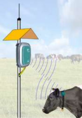
BU-500 (Base Unit) is a unit used to collect messages from tags and send them to central
management system.
The unit replies to each tag upon receiving a message. They unit is also used to set
various tag parameters and to update software inside the tag.
Outdoor unit powered from 24V DC via external AC to DC PS – 110/220VAC.
2.1 BU-500 Units contains Internal Antenna
Internal Antenna type: Internal diversity patch antenna, ~10dBi, directional
Antenna gain: ~12dBi (Max gain: 15dBi)
Average RF data: 3 messages/hour, 1mSec/message, ~30bytes/message per tag.
Option to connect External antenna with same parameters
P a g e 7
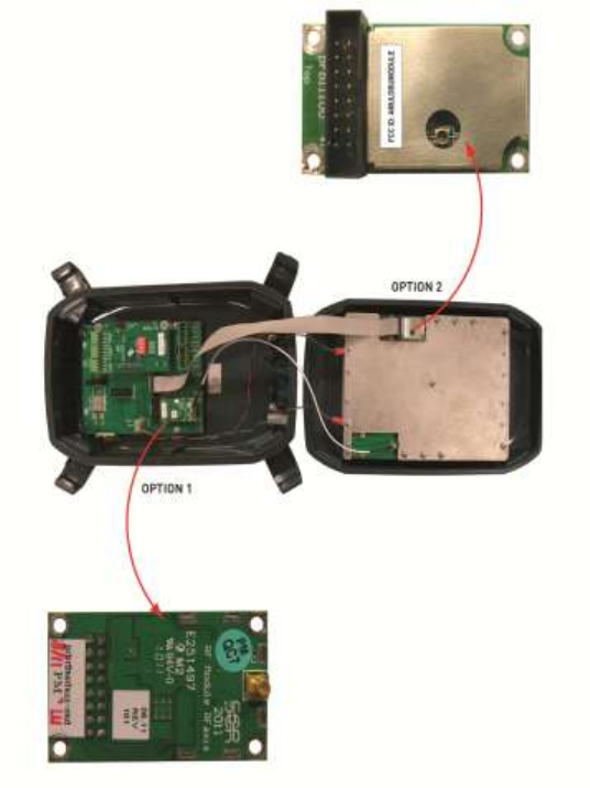
2.2 LD Module Options
Option 1: Direct assembly on BU-500 board with connection to antenna by coax cable.
Option 2: Direct assembly on the antenna with connection to BU-500 board by flat cable