SCR Engineers T03 Activity based tag User Manual SCR One
SCR Engineers Ltd. Activity based tag SCR One
Users Manual

SCR
AMUT03
HR-TAG-LDn
SPECIFICATIONS
Zeev K.
Ver 0.13
P a g e 2
Version History:
0.10
Initial version
0.11
Add NFC
0.12
Change product name to HR-TAG-LDn
0.13
Update product name to AMUT03
Contents
1. Global system specifications ................................................................................................... 4
1.1 System components ........................................................................................................ 4
1.2 TAG/IDU/BU communication overview .......................................................................... 5
2 HR-TAG-LDn Specifications ...................................................................................................... 6
2.1 General description ......................................................................................................... 6
2.2 2.4GhZ Transceiver Parameters .................................................................................... 6
2.3 Optic Parameters ............................................................................................................. 6
2.4 NFC Parameters ............................................................................................................... 6
2.5 Mechanical dimensions ................................................................................................... 7
2.6 Block diagram .................................................................................................................. 8
3 Environmental Conditions ....................................................................................................... 8
4 Installing the tag ...................................................................................................................... 9

P a g e 3
The FCC Wants You to know
NOTE: This equipment has been tested and found to comply with the limits for a Class B digital
device, pursuant to part 15 of the FCC Rules. These limits are designed to provide reasonable
protection against harmful interference in a residential installation. This equipment generates, uses
and can radiate radio frequency energy and, if not installed and used in accordance with the
instructions, may cause harmful interference to radio communications. However, there is no
guarantee that interference will not occur in a particular installation. If this equipment does cause
harmful interference to radio or television reception, which can be determined by turning the
equipment off and on, the user is encouraged to try to correct the interference by one or more of the
following measures:
-Reorient or relocate the receiving antenna.
-Increase the separation between the equipment and receiver.
-Connect the equipment into an outlet on a circuit different from that to which the receiver is
connected.
-Consult the dealer or an experienced radio/TV technician for help.
FCC Warning
Changes or modifications to this equipment not expressly approved by the party responsible for
compliance (SCR Engineers Ltd.) could void the user’s authority to operate the equipment
HR-TAG-LDn FCC ID: AMUT03
Manufacturer: SCR Engineers Ltd.
This device complies with Part 15 of the FCC Rules.
Operation is subject to the following two conditions:
(1) This device may not cause harmful interference, and
(2) this device must accept any interference received, including
interference that may cause undesired operation.
P a g e 4
1. Global system specifications
All units are for outdoor use, required Radio regulations according to target market &
Low voltage 24VDC regulation (except for tags which powered by internal battery).
1.1 System components
HR-TAG-LDn – Activity based tag with 2.4GhZ transceiver & IRDA receiver.
IDU530 – Tag identification unit with CAN-Bus network interface, IRDA
transmitter & 2.4GhZ Receiver ONLY .
IDU510 – Tag identification unit with SCR C.L. network interface, IRDA
transmitter & 2.4GhZ Receiver ONLY.
BU-500 – LD Base unit, with RS-485 network interface and 2.4GhZ transceiver.
BU-500E – LD Base unit, with 10BASE-T/100BASE-TX Ethernet network
interface.
P a g e 5
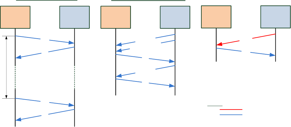
1.2 TAG/IDU/BU communication overview
Tag
Tag initiate sending data
BU500
Data
Ack
Tag
BU initiate sending messages
BU500
Ack
Message 1
Data
Ack
20 minutes
Message 1 retry*
Message 2
Ack
Tag IDU
Data
ID Req
Optic
RF
Legend:
Only IDU can initiate ID request
*When no ACK from tag
No retries when tag sends data

P a g e 6
2 HR-TAG-LDn Specifications
2.1 General description
Tag is a unit mounted on a collar on the animal neck, used for the following:
1. Identification of animal using 2.4GHz transceiver and optical IRDA receiver
and/or NFC reader unit.
2. Measure various animal parameters, processes and transmit them via 2.4 GHz to
the base unit (BU500/E) and/or local IDUxx.
The tag initiates transmissions of few messages each hour by predefine sequence or upon
request from IDUxx via IRDA receiver or BUxx units via 2.4GhZ link.
Outdoor installation, sealed unit, powered from internal 3.6V battery.
2.2 2.4GhZ Transceiver Parameters
RF Transceiver: Atmel AT86RF233
RF Frequency: 2.405-2.48GHz
Modulation type: QPSK
RF Channels: 5MHz separation 16ch
Baud Rate: 250K Bit/Sec (Not configurable)
Output power: 3.5dBm
Antenna type: PCB Omni-directional
Antenna gain: Average 0dBi (Max gain: 1.5dBi)
Average RF data: 3 messages/hour, 1mSec/message, ~30bytes/message.
2.3 Optic Parameters
IRDA Receiver – using to initialize tag parameters and ID transmission via 2.4GHz link in aim to
identify specific animal in specific location as milking station or passing gate.
2.4 NFC Parameters
Utilizing Passive internal NFC High Frequency inlay (IC and Antenna) complying with the
following standards
ISO/IEC 15693-2, -3
ISO/IEC 18000-3 Compliant
13.56-MHz Operating Frequency
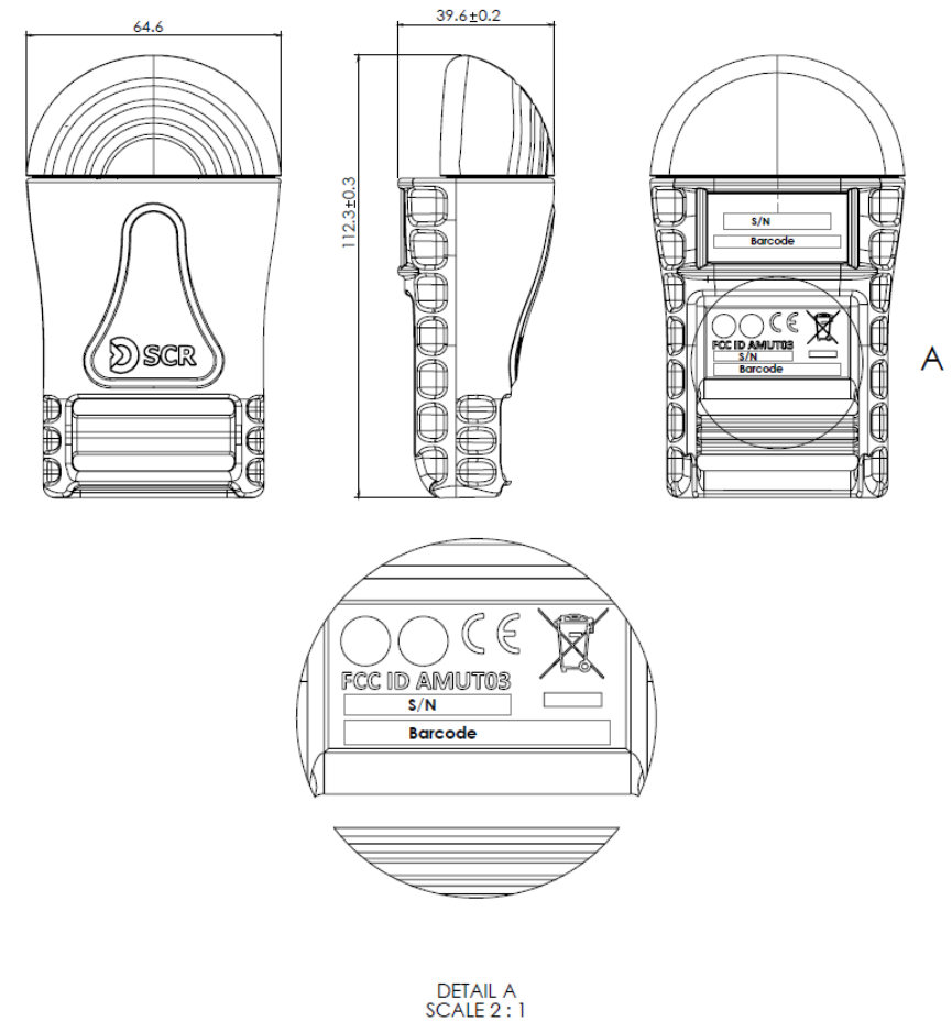
P a g e 7
2.5 Mechanical dimensions
All dimensions in mm
P a g e 9
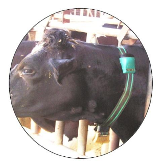
4 Installing the tag
It is important to correctly attach the tags to the cow's neck in a secure manner in order to
avoid them from turning or falling off.
To securely attach the tag to the cow’s neck:
1. Ensure that your tag assembly kit includes the following parts:
i. HR-TAG-LDn
ii. Belt, Weight & Buckle
2. Open the outside locker of buckle using the buckle opener (supplied with each
system) or a large flat screwdriver.
3. Mount the belt on the cow's neck in a way that the tag is positioned on the upper
left side of the cow’s neck (when looking from behind).
4. Closely fasten the belt around the cow’s neck with a maximum of 1-2 fingers gap
between the belt & the neck.
5. Tighten the buckle's lever to lock the belt. Make sure that the buckle is completely
closed and secured (pushed in all the way)
A properly mounted tag should look like this picture: