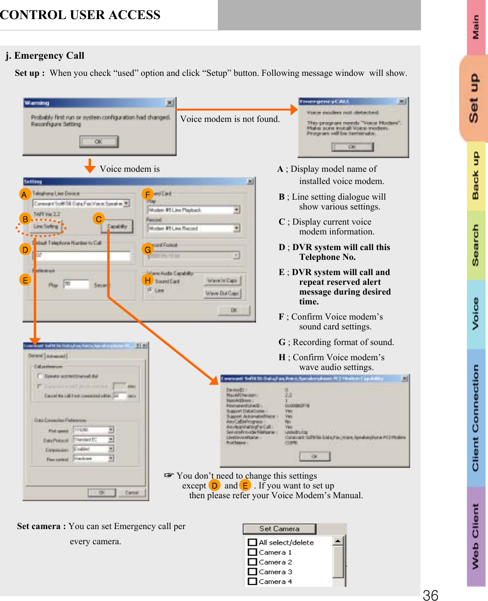
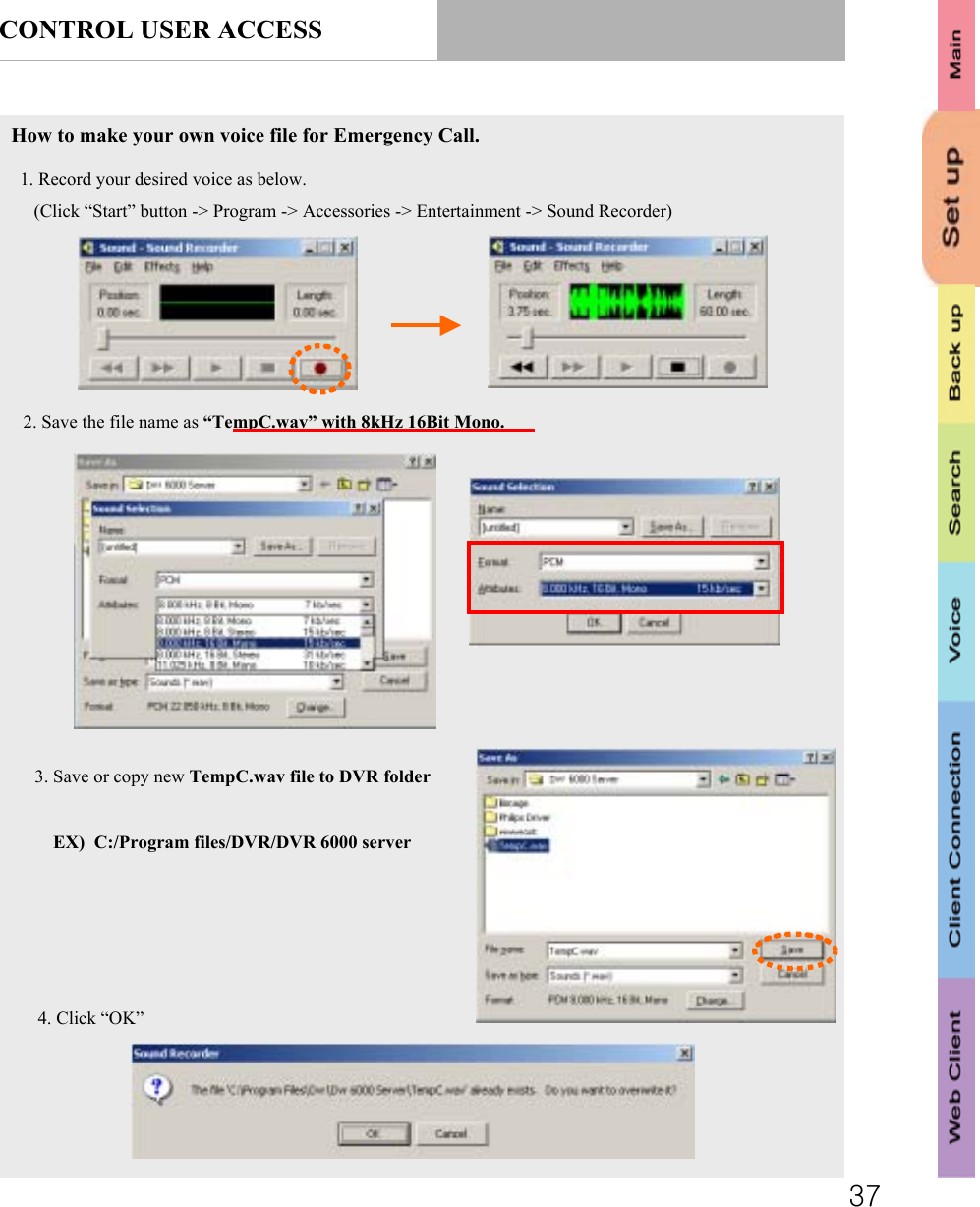
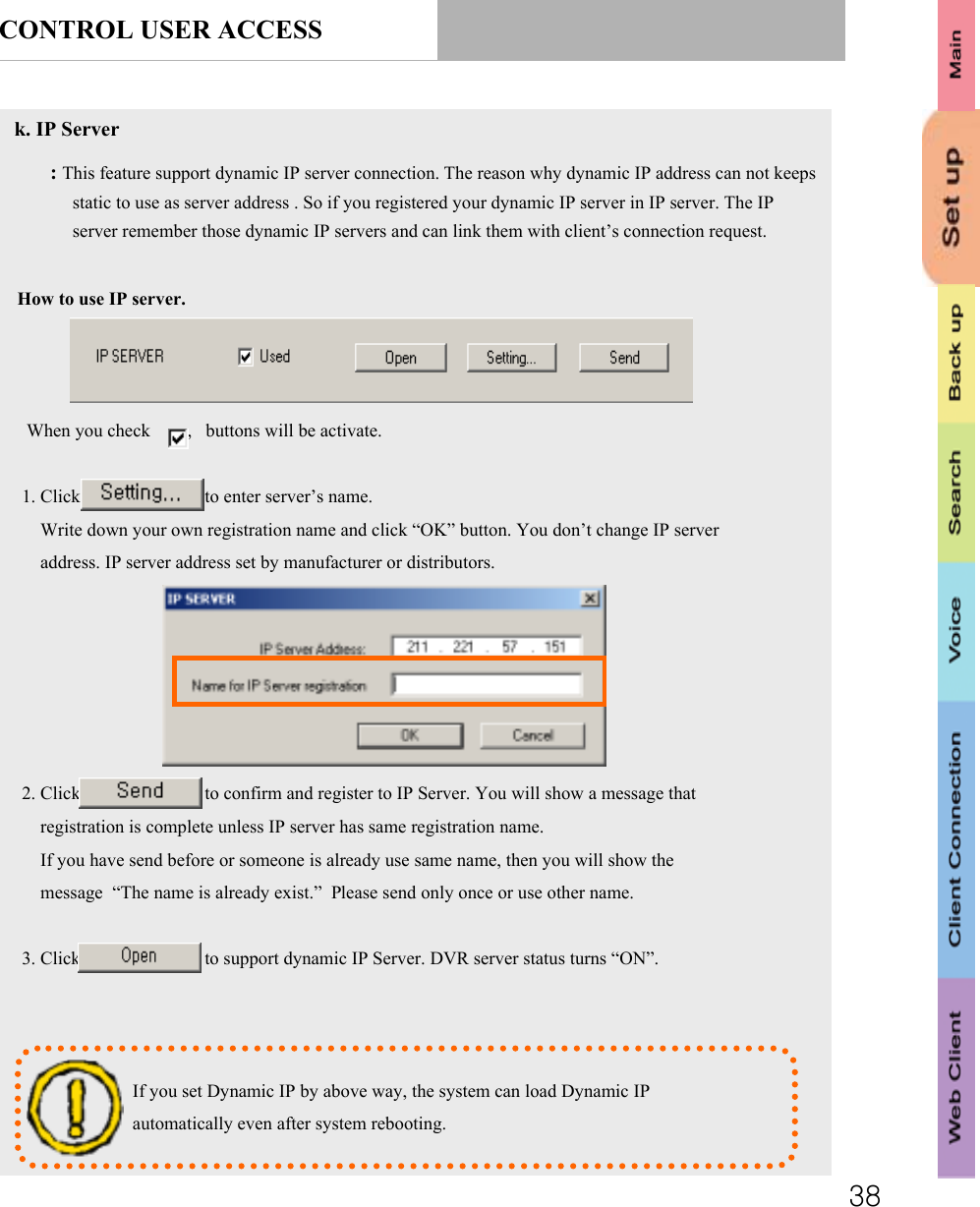
SEDO DF-7500 DVR BOARD User Manual USERS MANUAL
SEDO Co., Ltd. DVR BOARD USERS MANUAL
UserManual.wiki
>
SEDO
>
DF 7500 User Manual
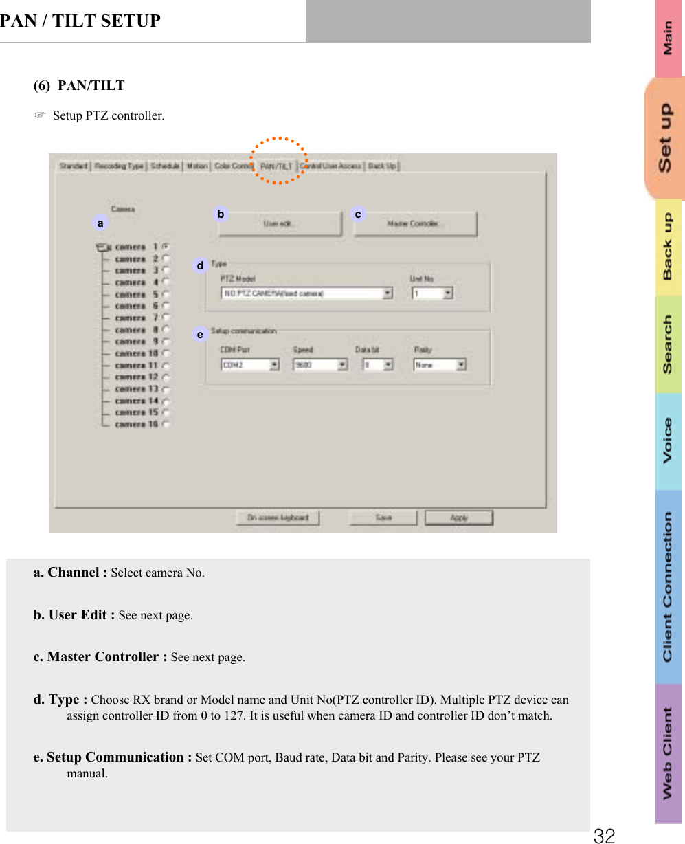
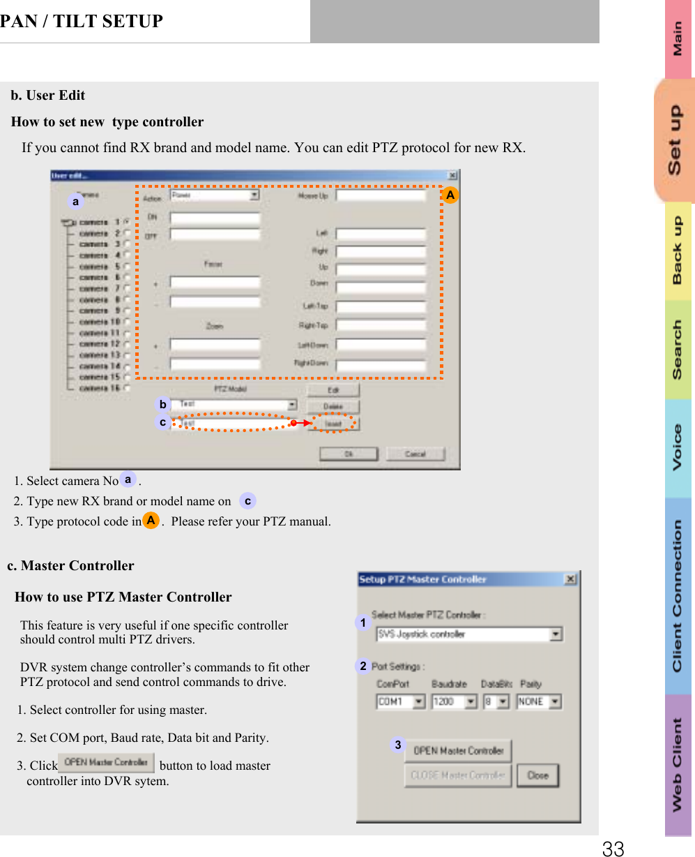
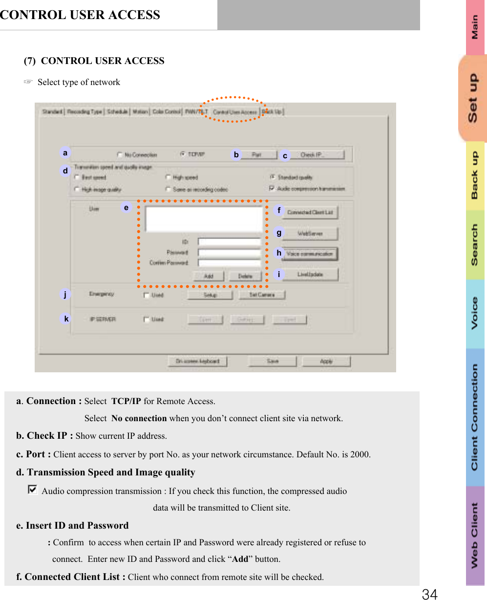
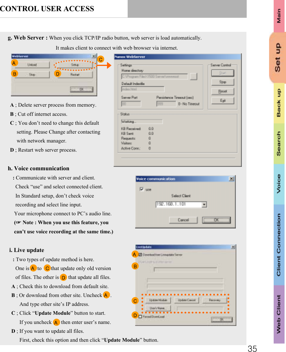
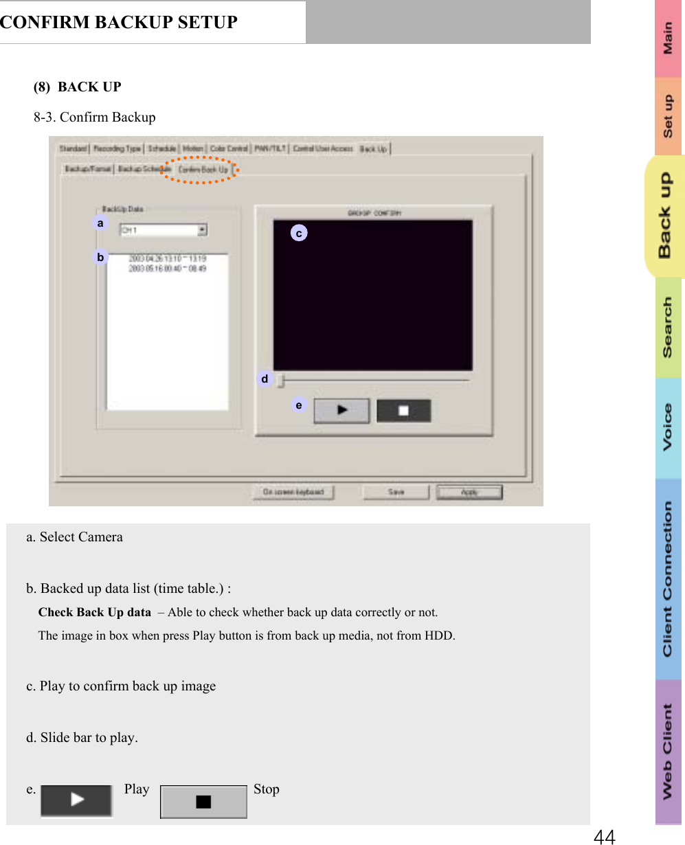
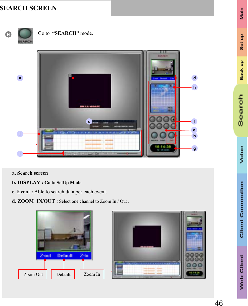
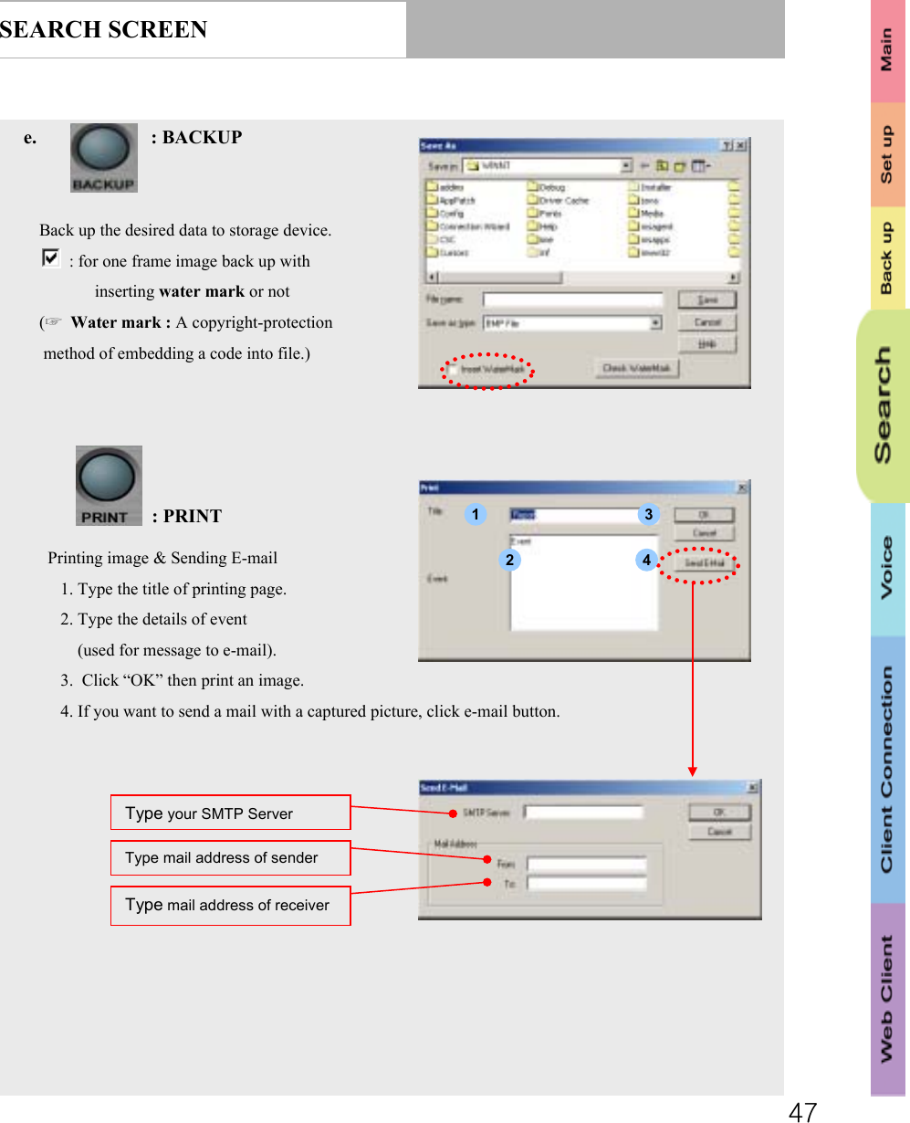
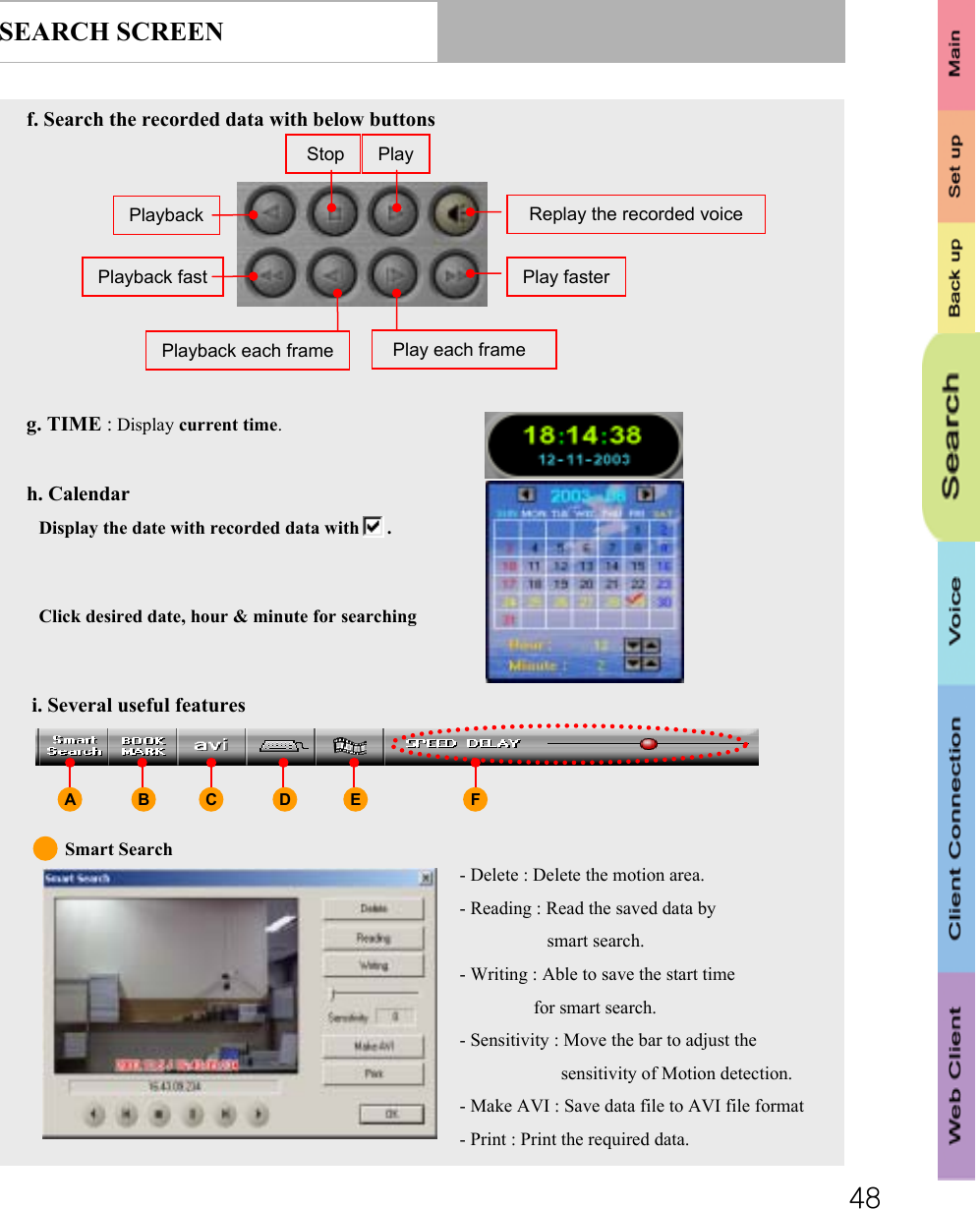
USERS MANUAL
Navigation menu
Upload a User Manual
Namespaces
Wiki Guide
HTML
PDF
Info
Views
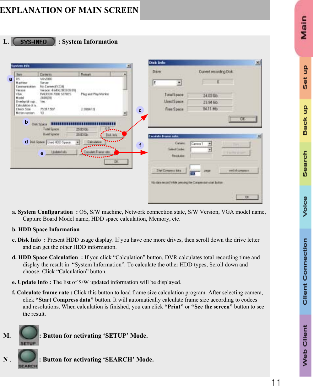
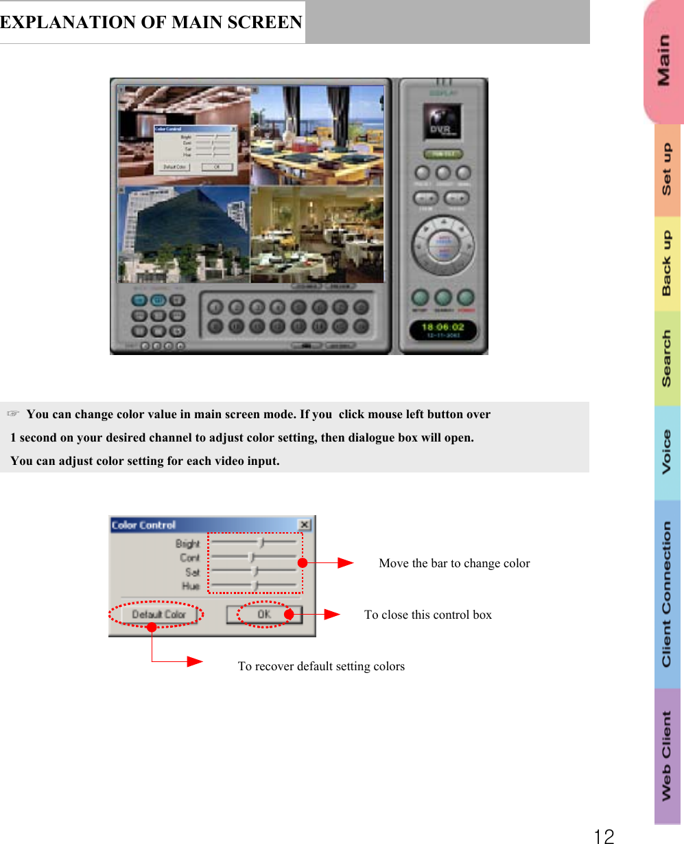
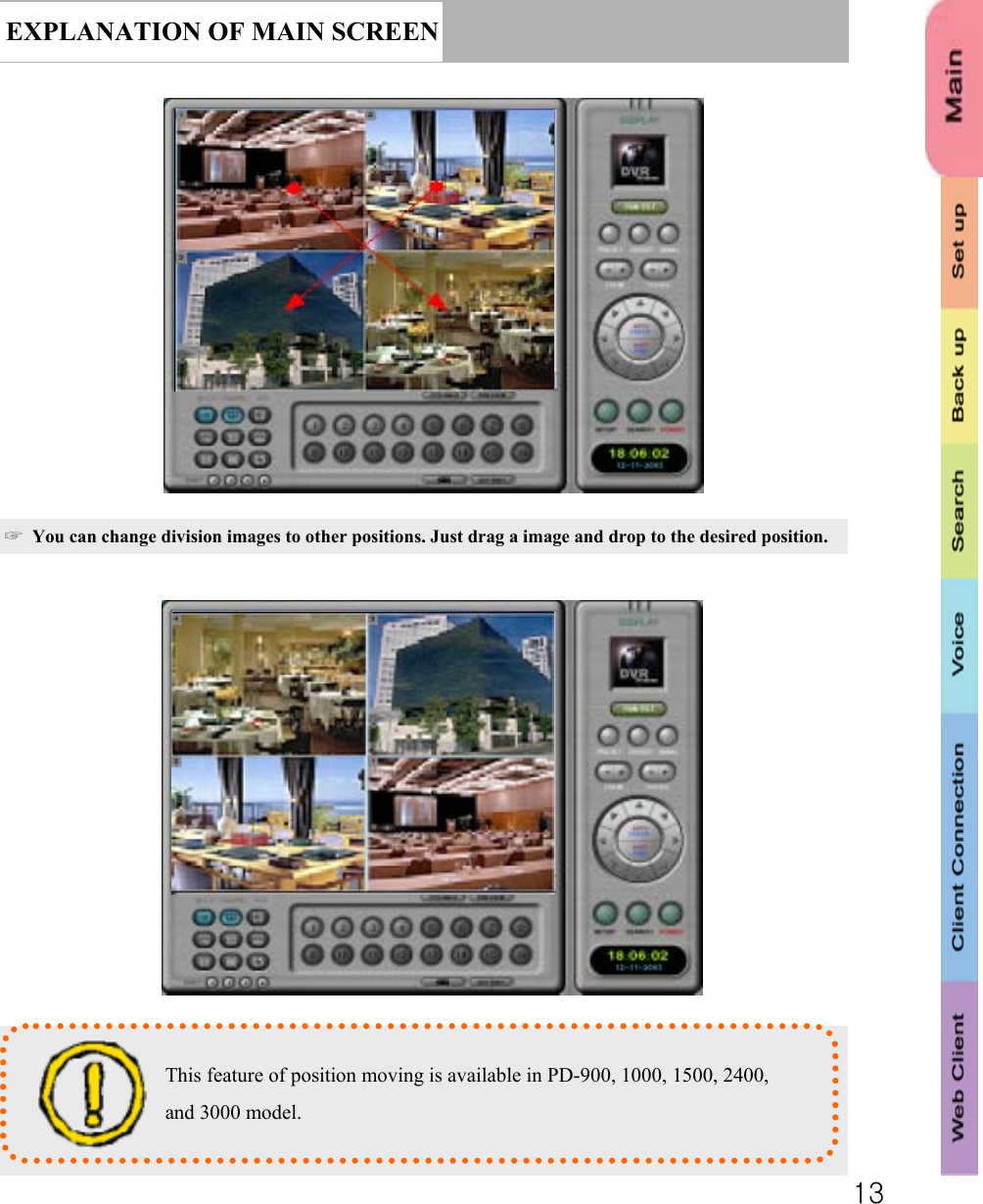
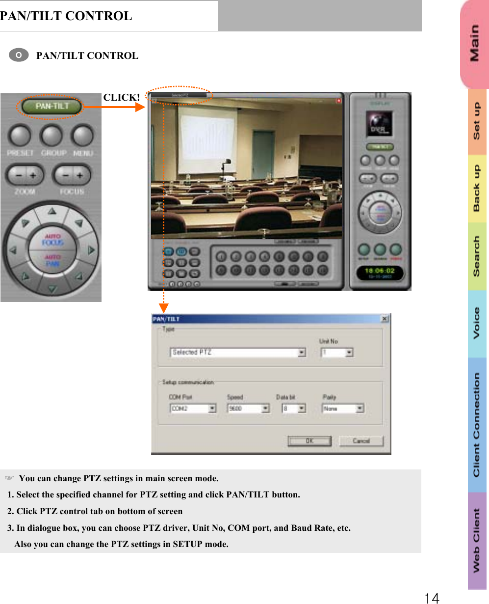
User Manual
Discussion / Help
Navigation