SEDO DF9400 16 Channel Digital Video Recorder PCI Type (DVR) User Manual
SEDO Co., Ltd. 16 Channel Digital Video Recorder PCI Type (DVR) Users Manual
UserManual.wiki
>
SEDO
>
DF9400 User Manual
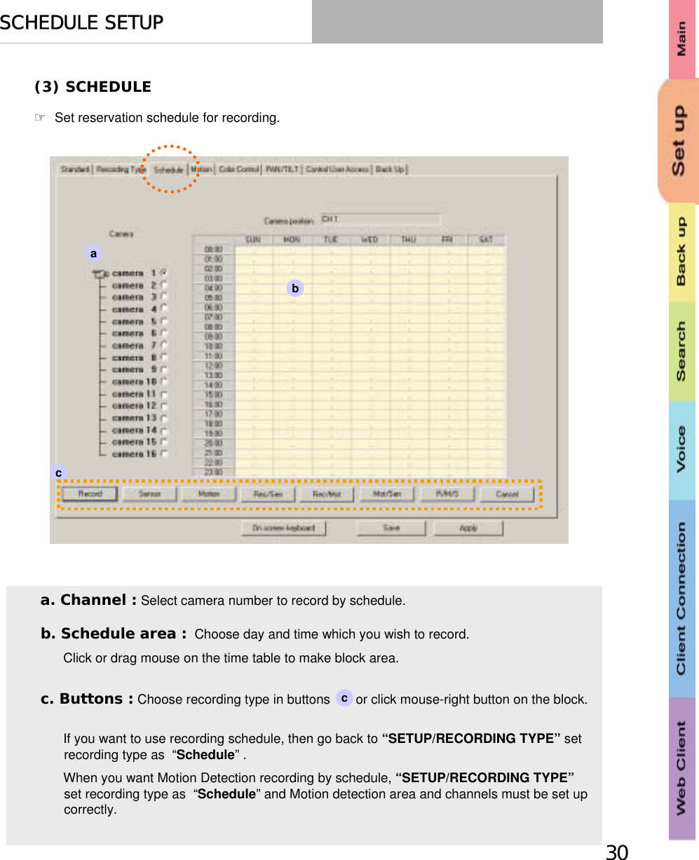
Users Manual
Navigation menu
Upload a User Manual
Namespaces
Wiki Guide
HTML
PDF
Info
Views
User Manual
Discussion / Help
Navigation