SEGA DKT06214 RFID Reader/Writer Transmitter User Manual Maxell
Sega Corporation RFID Reader/Writer Transmitter Maxell
UserManual.wiki
>
SEGA
>
DKT06214 User Manual
Users manual
Navigation menu
Upload a User Manual
Namespaces
Wiki Guide
HTML
PDF
Info
Views
User Manual
Discussion / Help
Navigation
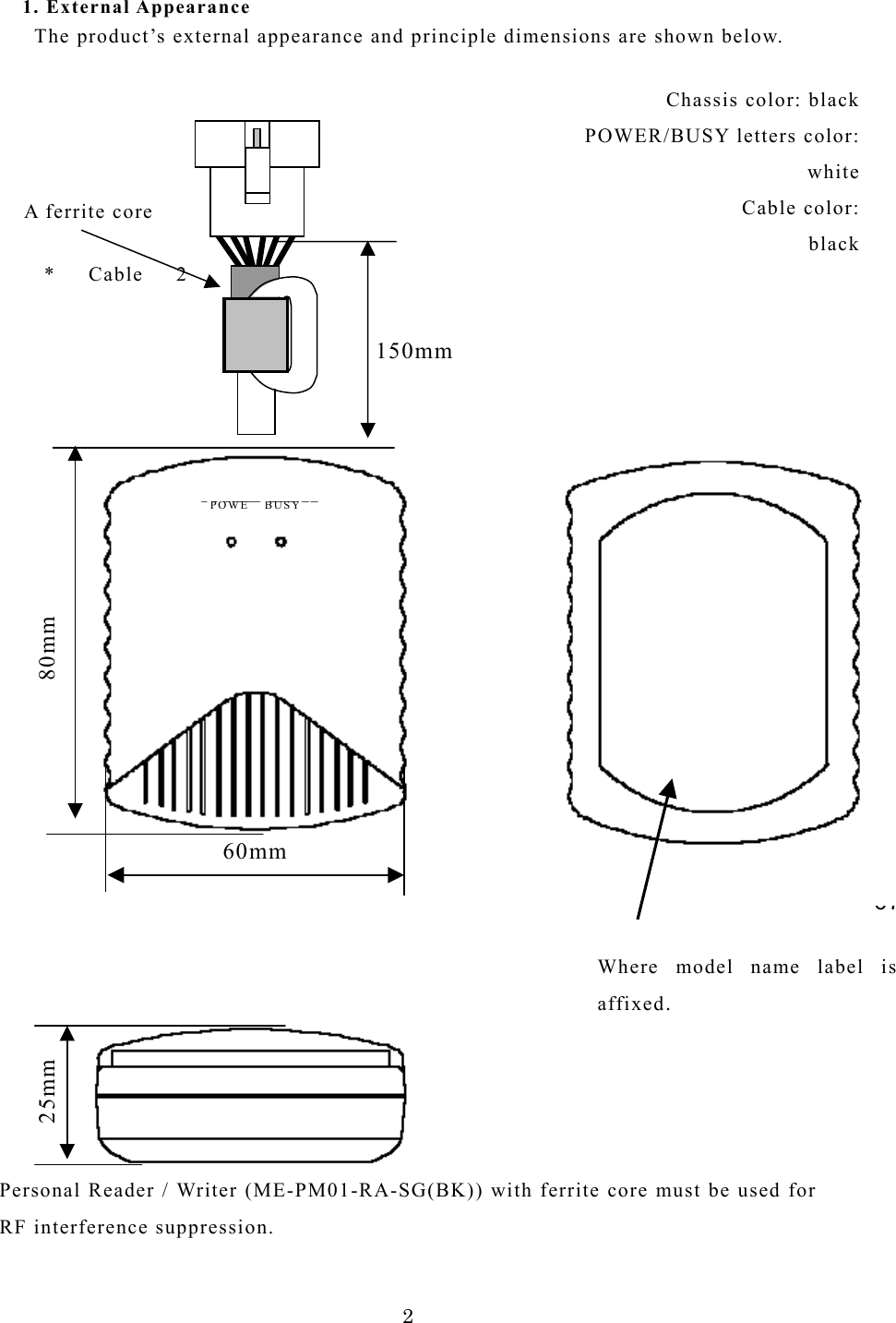
![6●FCC WARNING Changes or modifications not expressly approved by the party responsible for compliance could void the user’s authority to operate the equipment. Notice: This equipment has been tested and found to comply with the limits for a Class B digital device, pursuant to part 15 of the FCC Rules. These limits are designed to provide reasonable protection against harmful interference in a residential installation. This equipment generates, uses and can radiate radio frequency energy and, if not installed and used in accordance with the instructions, may cause harmful interference to radio communications. However, there is no guarantee that interference will not occur in a particular installation. If this equipment does cause harmful interference to radio or television reception, which can be determined by turning the equipment off and on, the user is encouraged to try to correct the interference by one or more of the following measures: -Reorient or relocate the receiving antenna -Increase the separation between the equipment and receiver. -Connect the equipment into an outlet on a circuit different from that to which the receiver is connected. -Consult the dealer or an experienced radio/TV technician for help. Personal Reader / Writer (ME-PM01-RA-SG(BK)) with ferrite core must be used for RF interference suppression. This device complies with Part 15 of the FCC Rules and RSS-Gen of IC Rules. Operation is subject to the following two conditions: (1) this device may not cause harmful interference, and (2) this device must accept any interference received, including interference that may cause undesired operation. This class [B] digital apparatus complies with Canadian ICES-003. Cet appareil numerique de la classe[B] est conforme a la norme NMB-003 du Canada.](https://usermanual.wiki/SEGA/DKT06214/User-Guide-657604-Page-6.png)