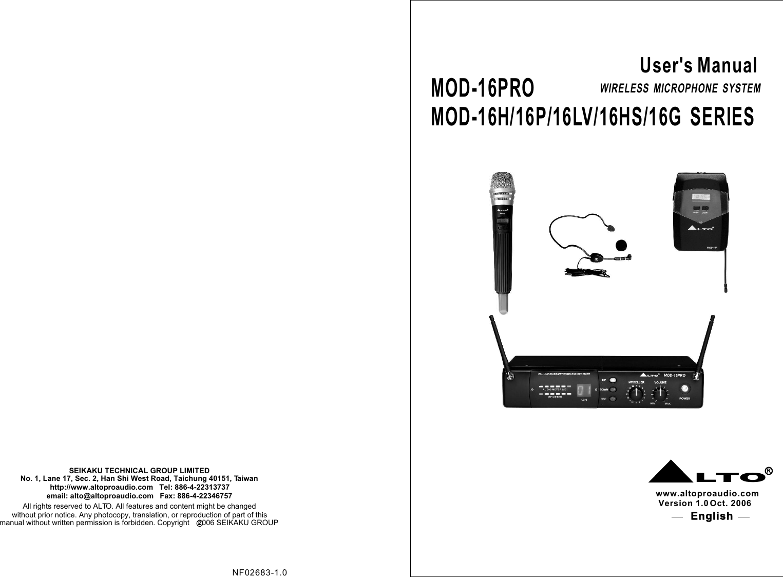
SEIKAKU TECHNICAL GROUP MOD-16PRO Wireless Microphone Receiver User Manual MOD 16PRO 16H 16P ALTO FCC

SEIKAKU TECHNICAL GROUP LIMITED Wireless Microphone Receiver MOD 16PRO 16H 16P ALTO FCC

Contents

User Manual 2

MOD-16PROMOD-16H/16P/16LV/16HS/16G  SERIESNo. 1, Lane 17, Sec. 2, Han Shi West Road, Taichung 40151, Taiwanhttp://www.altoproaudio.com   Tel: 886-4-22313737  email: alto@altoproaudio.com   Fax: 886-4-22346757All rights reserved to ALTO. All features and content might be changed without prior notice. Any photocopy, translation, or reproduction of part of this SEIKAKU TECHNICAL GROUP LIMITEDc manual without written permission is forbidden. Copyright    2006 SEIKAKU GROUP  User's ManualWIRELESS  MICROPHONE  SYSTEMLTORRwww.altoproaudio.comVersion 1.0 Oct. 2006English English NF02683-1.0
SAFETY RELATED SYMBOLS CAUTIONRISK OF ELECTRIC SHOCKDO NOT OPENThe symbol is used to indicate that some hazardous live terminals are involved within this apparatus, even under the normal operating conditions.The symbol is used in the service do-cumentation to indicate that specific component shall be only replaced by the component specified in that docu-mentation for safety reasons.Protective grounding terminal.Alternating current /voltage.ON:  Denotes the apparatus turns on.OFF:  Denotes the apparatus turns off, be-cause of using the single pole switch, be sure to unplug the AC power to prevent any ele-ctric shock before you proceed your service.WARNING:  Describes precautions that should be observed to prevent the danger of injury or death to the user.CAUTION:  Describes precautions that should be observed to prevent danger of the apparatus.WARNINGPower Supply Ensure the source voltage matches the voltage of the power supply before turning ON the apparatus.Unplug this apparatus during lightning storms or when unused for long periods of time.External Connection The external wiring connected to the out-put hazardous live terminals requires installation by an instructed person, or the use of ready-made leads or cords.Do not Remove any Cover There are maybe some areas with high voltages inside, to reduce the risk of electric shock, do not remove any cover if the power supply is connected. The cover should be removed by the qual-ified personnel only. No user serviceable parts inside.Fuse To prevent a fire, make sure to use fuses with specified standard (current, voltage, type). Do not use a different fuse or shortcircuit the fuse holder. Before replacing the fuse, turn OFF the apparatus and disconnected the power source.Protective Grounding Make sure to connect the protective grounding to prevent any electric shock before turning ON the apparatus. Never cut off the internal or external pro-tective grounding wire or disconnect the wiring of protective grounding terminal. Operating ConditionsThis apparatus shall not be exposed to dripping or splashing and that no objects filled with liquids, such as vases, shall be placed on this apparatus.To reduce the risk of fire or electric shock, do not expose this apparatus to rain or moisture. Do not use this apparatus near water.Install in accordance with the manufacturer's Hazardous live terminal .Disposing of this product should not be placed in municipal waste and should be separate collection.
IMPORTANT SAFETY INSTRUCTIONS Read these instructions.Keep these instructions.Heed all warnings.Only use attachments/accessories spec-   ified by the manufacturer.Power Cord and PlugDo not defeat the safety purpose of the polarized or grounding type plug. A polarized plug has two blades with one wider than the other. A grounding type plug has two blades and a third grounding prong. The wide blade or the third prong are provided for your safety. If the provided plug does not fit into your outlet, consult an electrician for replace-ment of the obsolete outlet.Protect the power cord from being walk-ed on or pinched particularly at plugs, convenience receptacles, and the point where they exit from the apparatus.Cleaning When the apparatus needs a cleaning, you can blow off dust from the apparatus with a blower or clean with rag etc. Don't use solvents such as benzol, alcohol, or other fluids with very strong volatility and flammability for cleaning the apparatus body. Clean only with dry cloth.ServicingRefer all servicing to qualified personnel. To reduce  the risk of electric shock, do not perform any servicing other than that contained in the operating instructions unless you are qualified to do so .Servicing is required when the apparatus has been damaged in any way ,such as power supply cord or plug is damaged , liquid has been spilled or objects have fallen into the apparatus, the apparatus has been exposed to rain or moisture, does not operate normally, or has been dropped.Follow all instructions.instructions. Do not install near any heat sources such as radiators, heat registers, stoves, or other apparatus (including am-plifiers) that produce heat. Do not block any ventilation openings. No naked flame sources, such as lighted candles, should be placed on the apparatus. 1. WARRANTY REGISTRATION CARDTo obtain Warranty Service, the buyer should first fill out and return the enclosed Warranty Registration Card within 10 days of the Purchase Date. All the information presented in this Warranty Registration Card gives the manu-facturer a better understanding of the sales status, so as to purport a more effective and efficient after-sales warranty service.Please fill out all the information carefully and genuinely, miswriting or absence of  this card will void any of your warranty service. 2. RETURN NOTICE2.1 In case of return for any warranty service, please make sure that the     product is well packed in its original shipping carton, and it can protect     your unit from any other extra damage.2.2 Please provide a copy of your sales receipt or other proof of purchase    with the returned machine, and give detail information about your return    address and contact telephone number. 2.3 A brief description of the defect will be appreciated. 3. TERMS AND CONDITIONS3.1   warrants that this product will be free from any defects in materials LTO    and/or workmanship for a period of 1 year from the purchase date if you     have completed the Warranty Registration Card in time. 3.3 During the warranty service,   may repair or replace this product LTO    at its own option at no charge to you for parts or for labor in accordance     with the right side of this limited warranty.3.4 This warranty does not apply to the damages to this product that occurred     as the following conditions: Instead of operating in accordance with the user's manual thoroughly, any    abuse or misuse of this product.Normal tear and wearThe product has been altered or modified in any way .Damage which may have been caused either directly or indirectly by    another product / force / etc.Abnormal service or repairing by anyone other than the qualified personnel    or technician. And in such cases, all the expenses will be charged to the buyer.3.2 The warranty service is only available to the original consumer, who purchased this product directly from the retail dealer, and it can not be transferred.2.4 Please prepay all the costs involved in the return shipping, handling and     insur-ance.188. WarrantyThis device complies with Part 15 of the FCC Rules. Operation is subject to the following two conditions: (1) this device may not cause harmful interference, and (2) this device must accept any interference received, including interference that may cause undesired operation.WARNING: changes or modifications not expressly approved by the party responsible for compliance could void the user's authority to operate the equipment.WARNING:MODIFICATION OF THIS DEVICE TO RECEIVE CELLULAR RADIOTELEPHONE SERVICE SINGALS IS PROHIBITED UNDER FCC RULES AND FEDERAL LAW.
TABLE OF CONTENTS1. .. . 1Introduction . ................................................................2. ...... ......... . ......................3Features .... . ............................3. .... . .. .... ...... ...................4Control Elements ........ . ..... ........ ..4. ... .. ... ... . .......................8Operation ... .. .. ... .........................5. Modelling Technology for Wireless Microphones..........116. Technical Specifications..................................................147. Annex..........................................................................168. Warranty......................................................................1817740.125  740.325  740.525  740.725  740.925  741.125  741.325  741.525  741.725  741.925  742.125  742.325 742.525  742.725  742.925  743.125  743.325  743.525  743.725  743.925  744.125  744.325  744.525  744.725 744.925  745.125  745.325  745.525  745.725  745.925  746.125  746.325  746.525  746.725  746.925  747.125 747.325  747.525  747.725  747.925  748.125  748.325  748.525  748.725  748.925  749.125  749.325  749.525 749.725  749.925  750.125  750.325  750.525  750.725  750.925  751.125  751.325 751.525  751.725 751.925 752.125  752.325  752.525 752.725  752.925 753.125 753.325 753.525 753.725 753.925 754.125 754.325 754.525 754.725 754.925 755.125 755.325 755.525 755.725 755.925 756.125 756.325 756.525 756.725 756.925 757.125 757.325 757.525 757.725 757.925 758.125 758.325 758.525 758.725 758.925 759.125 759.325 759.525 759.725 759.925 760.125 760.325 760.525 760.725 760.925 761.125 761.325 761.525 761.725 761.925 762.125 762.325 762.525 762.725 762.925 763.125 763.325 763.525 763.725 763.925 764.125 764.325 764.525 764.725 764.925 765.125 765.325 765.525 765.725 765.925 766.125 766.325 766.525 766.725 766.925 767.125 767.325 767.525 767.725 767.925 768.125 768.325 768.525 768.725 CH 101CH 100CH 102 CH 103 CH 104 CH 105 Ch106 CH 107CH 108 CH 109 CH 110 CH 111 CH 112 CH 113 CH 114 CH 115 CH 116 CH 117 CH 118 CH 119CH 120 CH 121 CH 122 CH 123 CH 124 CH 125 CH 126 CH 127 CH 128 CH 129 CH 130 CH 131CH 132 CH 133 CH 134 CH 135 CH 136 CH 137 CH 138 CH 139 CH 140 CH 141 Ch142 CH 143(For  other market)(For  U.S. market)
11. Introduction     LTO MOD-16 wireless systems have been designed for Vocalists, Presenters     and performing Musicians. These wireless systems are based on a sophisticated     and innovative PLL circuit but, at the same time, are worry-free and easy to      use. Large back lighted displays are available both on the Receiver and the      Transmitters and simple Menus allow for a large number of functions such     as Frequency Select, Sensitivity, Muting, etc. But what makes the MOD-16      wireless systems truly unique is the MODELING circuit. Special Models have     been created for human voice as well as for electric guitar and bass so that     your MOD-16 wireless system allows for unprecedented flexibility of sound.      It is like to have 16 different systems in one system only.    Please read this Manual carefully before operation and enjoy playing with     your MOD-16 system!    Your MOD-16 system comes with a MOD-16PRO wireless Receiver and either    one of the following Transmitters:MOD-16PRO ReceiverMOD-16HIt is a handheld transmitter with rubberised finished and hi-fi level microphone capsule.7. ANNEXMost countries closely regulate the radio frequencies used in the transmission of wireless information. These regulations state which devices can use which frequencies, and help to limit the amount of RF(radio frequency)interference in all wireless communications. To be flexible enough to operate worldwide, MOD-16PRO Wireless receivers  are available in a number of models, each with a unique frequency range. Each frequency range, or band, spans up to 24MHz of the wireless broadcast spectrum. 7.1 Frequency Band Selection 7.2 Frequency Ranges16(For  Europe market)
2Type: Dynamic Mic.Frequency response: 50Hz~16kHz( 3dB)Impedance: 300   20% at 1kHzSensitivity: -71dB  3dBDirection: Omni-directionalMOD-16P/16LV/16HS/16GA bodypack transmitter with belt clip. The MOD-16P transmitter will come with either:1.A cable to be connected to an electric guitar or bass(MOD-16G)2.A Lavalier Microphone. This is the little "bug" to be clipped on ties, shirts, nipples,   Etc.(MOD-16LV)3.A Headset Microphone that is fit like a pair of sunglasses so that the Player has    both hands free to play an instrument, dance, shot the Audience, etc.(MOD-16HS)15MODELOscillation modeCarrier frequency bandFrequency responseFrequency stabilityT.H.D.Modulation modeRF output powerDynamicTone frequencyCurrent drainMax. DeviationBatteryOptionalMic. Capsule(optional)DimensionsWeightMOD-16HPLL UHF SYNTHESIZEDUHF 470-900 MHzDependent on applicable country regulations50 Hz-15KHz ( 3dB)0.005% (-10 ~ 50 )FM (F3E)5-50mW(adjustable 3 bands)100dB 30-33 KHz100mA35KHz "AA" type   2 Nickel hydrogen battery +chargerCondenser or Dynamic Capsule277  36.5mm (10.9" 1.44") 0.246Kg MOD-16P/16LV/16HS/16G1KHz<0.8%Condenser or Dynamic Capsule0.082Kg 97mm 6 8mm 2 2mm(3.82" 2.68" 0.87")SPECIFICATION
3HM-38, Condenser microphonePreset impedance: 600ohm; Freq. response: 80-12KHz;Sensitivity: -68dB+/-3dB at 1KHz;Directional: Uni-directional; Weight: 52g (0.12Ib)2. Features FEATURES OF MOD-16PRO, PLL UHF DIVERSITY RECEIVERThe friendly User Interface including two digit displays and intuitive MENU   system for easy operation.2 Antennas and switching diversity circuitSelector for three different output levels depending of kind of receiver usedSquelch control to minimize noise. FEATURES OF MOD-16H/16P/16LV/16HS/16G TRANSMITTERSSoft touch rubberised painting to avoid handling noiseRechargeable battery designSelector for three different output levels depending of kind of receiver usedLCD displayBattery status displayMute function (this function is very welcomed by Politicians...)Lock function to avoid miss action during a live performanceEach MOD-16 System complies with EMC regulations and includes 100 different channels. (Not all channels may be available in certain Countries depending on local regulations).They are manufactured under ISO9000:2000, ISO/TS 16949:2002 quality management system.LM-10, Clip microphonePreset impedance: 680ohm; Freq. response: 50-12KHz;Sensitivity: -65dB  3dB at 1KHzDirectional: 12 180mm                   ( 0.47" 7.1")Weight: 22g(0.049Ib)14Frequency bandReceiver typeFrequency responseFrequency stabilityT.H.D.Modulation modeS/N RatioDynamicRF sensitivityAudio outputBalance outputPower supplyDimensionsWeightMulti-channels, up to 100 frequency presets for each frequency bandsUHF 470-900 MHzDependent on applicable country regulationsPLL UHF SYNTHESIZED50 Hz-15KHz ( 3dB)0.005% (-10 -50 )1KHZ 0.8%FM (F3E)90dB100dB-100 dBm/30dB SINADUnbalanced 6.3mm phone jack 550mV ;20KHz deviation1.1V ,  20KHz  deviationDC 15V/ 500mA(AC 115V/230V 50/60Hz adaptor)217(W) 122(D) 44(H)mm;(8.2"  6.1"  1.7)              0.385KgMODELChannel MOD-16PRO6. Technical Specifications
43. Control Elements:3.1 MOD-16PRO, PLL UHF Diversity Receiver FRONT PANEL1 Power Switch: We are afraid you can not use the MOD-16R if you    don't switch the Power ON!2 UP/DOWN Keys: You can adjust the right values through these two keys    once the MENU is activated.3 DISPLAY: This double digit display shows you the number of channel operating     on your MOD-16PRO. The same number must appear on your Transmitter    for proper functioning.4 AF Display: It shows the level of the incoming audio signal. When "0"    LED lights up the incoming audio signal is optimized and will not present    distortion. If the "+6" LED lights up, the audio signal is overloaded and     you will hear distortion. If only the "-12" LED lights up only 10% of the     available signal reaches the Receiver. For optimal sound reproduction,     please do not exceed the "0" level.5 RF Display: It shows the level of the incoming radio signal. Optimum reception     is granted when all the LEDs light up. If no LED lights up, there is minimum     or no radio signal coming into the Receiver. If only a few LEDs light up you    may still operate the system but it means you are in a poor reception mode   due to Antenna positioning, distance in between Receiver and Transmitter. 6 MENU Key (SET): Via this key you can activate the desired function described above.7 Modeller: Adjust this knob to select the right modelling preset you wish to perform. There are total 16 options for you. Please refer to 5. Modelling Technology for Microphones for further details. 99119988772233445566Ok, enough with numbers. Let's start to familiarize with your MOD-16 System. First of all, the MOD-16PRO Receiver:13MODEL 7: MID-WARMTH, a moderate voice enhancement making use of Bass enhancer.MODEL 8: GROOVY- to add a touch of groove to Male and Female Lead Vocalist. Perfect for Blues.MODEL 9: SHARP- makes human voice quite crispy. Perfect for voice poor in high frequencies or if you get a cold...MODEL 10: KARAOKE- yes, microphones are used in a very peculiar way in Karaoke Bars and Venues. Usually the sound systems there are poor. Use this Model to add high frequencies and have your voice sound like a Pro's!MODEL 12: HEAVY METAL- This model will make your voice sound very aggressive. Good for Rock & Roll and if you have an argument with your Mother in law...MODEL 11: PIANO BAR- it similar to the Karaoke Model but we have also added key low frequencies to give the voice more body.MODEL 5: DE-ESSER- The name tells everything. Use it to de-emphasize the sibilants, like the letter sound 's', for example, from your vocals.MODEL 6: VINTAGE RADIO- Old tube based Receivers made the Announcer voice sound like... yeah, we call it Vintage. Try it for a smooth satin voice. Ideally used for speech, but we found some other neat applications in the studio as well!MODEL13: DISCO- It is similar to the Heavy Metal model but more tailored for Disco Music.MODEL14: CHOIR- Selected frequencies have been manipulated to make thisModel suitable for more than one vocalist when singing in a choirMODEL 15: FEMALE VOICE- Female Singers voices present a frequency response that is quite different from the Male voice. This Model gently adds certain low frequencies to make the female voice more consistent and at the same time will make the highest frequencies of the female voice more sparkling and defined.MODEL 16: PIANO BAR CHOIR- It is a combination of the Karaoke Model and the Piano Bar Model. Good when more than one voice is singing along together.
5 THE REAR PANEL1   1    2   2   3   3   3.2 THE MOD16H Handheld Transmitter3   3   7   7   6   6    1   1   2   2   4   4   5   5   1  Audio Output XLR: To connect a balanced cable with XLR connector (Yes,    we forgot to tell you that although your MOD-16 system is wireless, you    still need to connect the receiver to your Mixing Desk and to a wall plug!)2  Audio Output Jack: To be used with an unbalanced cable and standard    1/4" mono jack.3  DC Input: You can connect the supplied Adapter to this socket.4  Squelch: The job of a squelch circuit is to reduce audible noise.5  LOW-MID-HIGH Key: By pressing this key you can change the Audio     Output level of your transmitter:    LOW = -12dB    MID = -6dB    HI = 0dB5   5   448  Volume Control: This knob sets the audio signal level outputted through the balanced and unbalanced output jacks on the rear panel. Turn the knob clockwise fully for the max volume, and turn the knob counterclockwise fullyfor the min volume.9  Antenna Input Sockets: Includes 2 antennas to secure the Diversity function.     For optimal radio reception antennas should be placed vertically. You can    fold the antennas inward for convenience of transportation.microphone capsules for their wireless systems but this flexibility is far behind the wide choice of tones or "models", as we call them at  LTO. In fact, a specific model of wireless microphone may be used by a male vocalist or female vocalist during a live performance, by a Priest in a church service, by a speaker during a seminar, by and aerobics teacher during a training lesson, by a DJ, by a choir, by an announcer, by an auction director, we could go on and on forever with endless applications. It is now evident that each one of these users would benefit from a different tone or "model". But even the same user would like to get a different voicing or "model" depending on the style he is singing. What model serves the musicbest?  It's fair to say that it will be different whether he's singing Rock, Blues, or Folk and, of course can also change from song to song.  It is unlikely to buyseveral different microphone capsules in order to get different tone or "model"depending of the kind of use of performance. This would be unpractical, since it would be impossible to change a microphone capsule during a performance, not to mention the cost involved.LTO has therefore created and integrated in some of its wireless receivers a range of MODELS. Using these 16 different MODELS the user can select different sound patterns simply with the turn of one knob. There are preset MODELS for male and female Vocalists, DJ, Speakers, Announcers, and more.In a few words, with the  LTO modelling technology applied to wireless systems, the User can "fine tune" the sound of his microphone in 16 different ways.12Here is a List and description of the MODELS available on the  LTO Receivers:MODEL 1:  FLAT- In this position the Modeller is in bypass mode. The  LTO Modeller is not adding any character to the Audio OutputMODEL 2: CONFERENCE- To be used during Meetings. Especially made for speech and to avoid the typical boominess of many wireless microphones used for such purpose.MODEL 3: BROADCAST- This Model will add a certain character to the signal. It is typical of the Male Announcers through a solid state Transmitter. MODEL 4: WARMTH- Good for Lead Vocalist Male and Female.It will make the Male voice warmer and the Female voice more body.
6SELECT Key: Once you are in edit mode you can access this key to edit certain parameters. Press this key for a few seconds and the unit will enter in the MUTE mode. (In this way, you can tell your Bass Player what you think about the Sound Engineer without everybody knowing that!). Press it again for a few seconds and you will unmute the unit.Battery Compartment: This unit may be powered from one pair of dry or rechargeable batteries, Um3 size AA 1.5V. 5   5   Charge Jack: With the rechargeable batteries putting inside, use the charger supplied in your system to recharge the batteries. 6   6   Antenna: The Antenna of your MOD-16H is integrated in the microphone body. Please do not cover the antenna for optimal RF transmission.7   7   CH/ON Key: If you press this key for a few seconds your Transmitter will switch ON and OFF. Once you have switched the unit ON, just press this key again slightly and you can edit various parameters such as CHANNEL, GROUP, RF POWER LEVEL and LOCK/UNLOCK. Once you are in the LOCK position no further operation is allowed and, in a few seconds, the display will show the current channel selected (0 to 99). Battery level will also be shown. battery status  Front Grill: This spring steel mesh grill will protect the microphone capsule  during a live performance. Especially made for heavy metal players, alcohol,  drugs, etc..1   1   LCD Display: This nice blue LCD will indicate the current operation status.2   2   4   4   3   3   11- Mute FunctionSometimes, there are things that you want to tell to your Friends on stage or your nearby Companion during a Meeting but not necessarily to the rest of the world especially if you are live on CNN... A smart feature on your Transmitter allows you to easily MUTE the microphone so you are free to talk to the people next to you without the rest of the world hearing what you say. To enter into MUTE function simply press the SELECT key for a few seconds and the Transmitter will mute any audio signal going to the Receiver. Press SELECT again for a few seconds and you will UNMUTE the Transmitter.Note: Why Alto Transmitters come with 100 different frequencies? Not because you will need to use 100 different microphones at the same time. It is unlikely that you will use more than 8 systems at the same time so why 100 frequencies?This depends mainly of Countries regulations. We offer frequencies from 470 to 900 MHZ. Some of these frequencies are illegal in certain Countries and vice versa. Offering such a wide range of frequencies we make sure that each single Country on the planet will have more than enough choice of frequencies available. Not only: A certain frequency can be to close to the frequency generated by lighting equipment, a computer, a fax machine and so on. Therefore, thanks to the large number of frequencies available you can easily switch to another frequency that is interference-free. 5. Modelling Technology for Wireless MicrophonesThis document applies to all  LTO Wireless Receivers used in conjunction with LTO Handheld and Bodypack TransmittersFundamentals:  LTO has created and integrated a wireless microphone system offering 16 modelling presets resulting in a range of tonal response for a wide variety of applications.  Until this innovative introduction made for the first time in the world in a wireless system by  LTO, wireless systems consisting of receiver and microphone transmitters produced a single sound pattern. Each microphone capsule design, because of the laws of physics, features its own frequency response and adds a certain tonal colour to the signal it transmits. If you do not like the colour added, you must change the microphone section of your transmitter, much like a painter chooses a different colour from his palate. Many brands today offer several different
71. LCD display: This nice blue LCD will indicate the current operation status.2. CH-ON Key: If you press this key for a few seconds your Transmitter will     switch ON and OFF. Once you have switched the unit ON, just press this     key again slightly and you can edit various parameters such as CHANNEL,    GROUP, RF POWER LEVEL and LOCK/UNLOCK. Once you are in the LOCK    position no further operation is allowed and, in a few seconds, the display    will show the current channel selected (0 to 99). Battery level will also be    shown.3. SELECT key: Once you are in operation mode you can access this key to     edit certain parameters. Press this key for a few seconds and the unit    will enter in the MUTE mode. (In this way, you can tell your Bass Player    what you think about the Sound Engineer without everybody knowing that!).    Press it again for a few seconds and you will unmute the unit.4   4   Mini 4P Connector: This connector is used to connect the unit with the clip microphones, for example, HM-38 condenser microphone or LM-10 clip microphone.3   3   1   1    4   4   2   2   Pin 2, GNDPin 4, for Dynamic or Condenser microphoneCharge Jack: With the rechargeable batteries put inside, use the charger supplied in your system to recharge the batteries. 5   5   Battery Compartment: This unit may be powered from one pair dry or rechargeable batteries, UM3 size AA 1.5V. 6   6   Pin 3, Phantom power supply for Condenser microphonePin 1, for guitar, bass and keyboards3.3 MOD-16P/16LV/16HS/16G, Body Pack Transmitter3   3   1   1   2   2   5   5   4   4   8   8   7   7   6   6   10-  RF Output Power SelectYour Transmitter can operate on three different levels of output power. These are different form the Handheld Model and the Bodypack model.To select the proper Output Level, please press the CH/ON key three times and you will access the OUTPUT LEVEL Menu. Then press the SELECT key to change the output level from PL 0 to PL 2. IN a few seconds your setting will be automatically stored and the display will show again the operating frequency.You don't want accidental change of frequency or other setting in the middleof a performance, do you? Any miss-operation during a live performance can be easily avoided thanks to the LOCK function. With the LOCK function ON no further change of setting is allowed until the Transmitter is unlocked. To access the LOCK menu press the CH/ON key four times and then press the SELECT key to lock or unlock the Transmitter Settings. Your choice of setting will automatically be saved into the Transmitter in a few seconds. The blue display shows "lock" and "unlock" depending on the operating mode.-  LOCK  FunctionFig 4: LOCKFig 5: UNLOCKFor the Handheld model the levels are- PL 0, the output power is 5dBm;- PL 1, the output power is 10dBm; - PL 2, the output power is 15dBm; and for the Bodypack version the levels are- PL 0, the output power is 3dBm;- PL 1, the output power is 5dBm; - PL 2, the output power is 12dBm;
8OK, if so far you remember all the functions and features of your Mod16 System you are ready to operate the Unit. Let's start from the Receiver:4. OperationFirst, turn the Unit ON. With your Transmitter in ON position, check the Channel Number indicated on the Transmitter display. Now, press the UP/DOWN keys untilthe same value is shown on the double digit display of your MOD-16 Receiver. OnceReceiver and Transmitter are synchronized the LED Meters for Audio signal and Radio frequency will light up.- Audio Output LevelThe volume control knob adjusts the amount of audio signal to be sent to themixing desk through the balanced or unbalanced output sockets on the rear panel. Turn the volume knob clockwise for maximum output and counterclockwise for minimum output volume.- Squelch Control:A squelch circuit is responsible to minimize audible noise during operation.Such circuit will mute the Receiver every time the incoming audio signal drops below a certain threshold. You must use the squelch control with maximum care. If the threshold is too high the squelch circuit will not only cut the noise but also mute certain low-level audio signals. Please experiment various threshold levels before Live operation and choose the most appropriatefor your event.Antenna: It is a flexible antenna. To get effective transmission, never cover the antenna with hand, clothes, etc during the operation, and always position the transmitter nearby the receiver.8   8   Belt Clip: It is a detachable belt clip for easy carry during the live applications. 7   7   4.1 For the MOD-16PRO, PLL UHF Diversity Receiver94.2 For the MOD-16H/16P/16LV/16HS/16G transmittersPreset Channel Remaining battery lifePress the CH/ON key for a few seconds and the transmitter will be powered ON. At this point the blue back lighted display will show:The channel at which the unit is operating    The Battery StatusWith the Transmitter switch ON you can slightly press the CH/ON key again and you will access to the following parameters:Preset Channel  RF power level   Lock/UnlockAnd now that you know how to operate your Mod16PRO Receiver, let's learn how to use the MOD-16 Transmitters. The following instructions apply both to the handheld version and to the bodypack version.There are 2 keys on the Transmitter labelled CH/ON and SELECT.In your Transmitter there are 100 frequencies. Each Group accordingto EMC regulations. To select a frequency you must first switch your Transmitter ON by pressing the CH/ON key for a few seconds until you hear the beep and the blue display is lighted. Then press the CH/ON key again slightly and you will access the CHANNEL menu. At this point use the SELECT key to change the frequency value from 1 to 99. Your setting will be automatically saved in a few seconds and the display will go back to the main menu showing the operating frequency.

Navigation menu