SEIKAKU TECHNICAL GROUP PEM-500T Wireless Microphone User Manual NMCQV 521 UH5000
SEIKAKU TECHNICAL GROUP LIMITED Wireless Microphone NMCQV 521 UH5000
UserManual.wiki
>
SEIKAKU TECHNICAL GROUP
>
PEM 500T User Manual
User manual
Navigation menu
Upload a User Manual
Namespaces
Wiki Guide
HTML
PDF
Info
Views
User Manual
Discussion / Help
Navigation

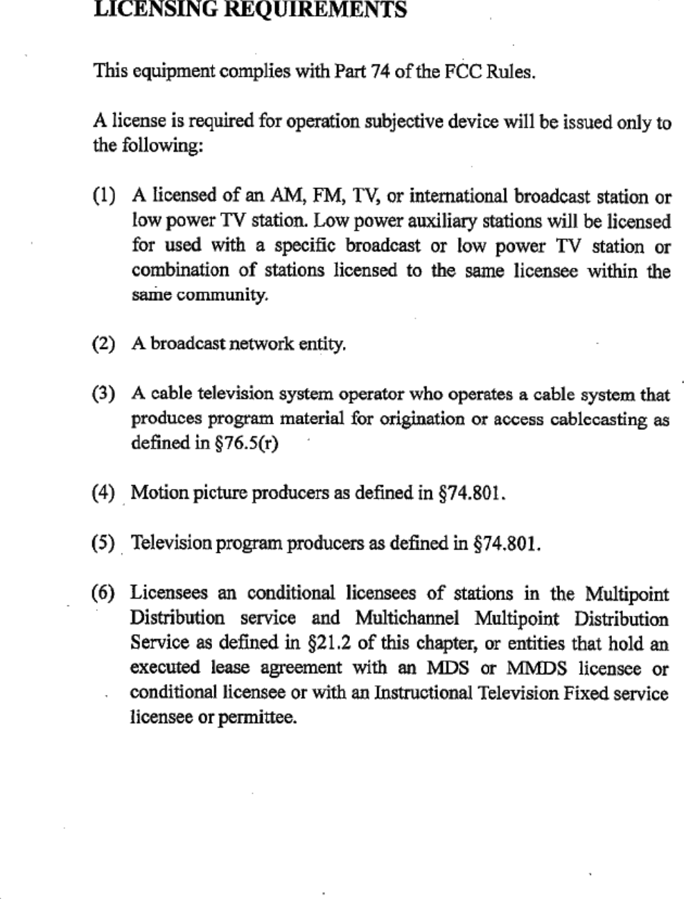


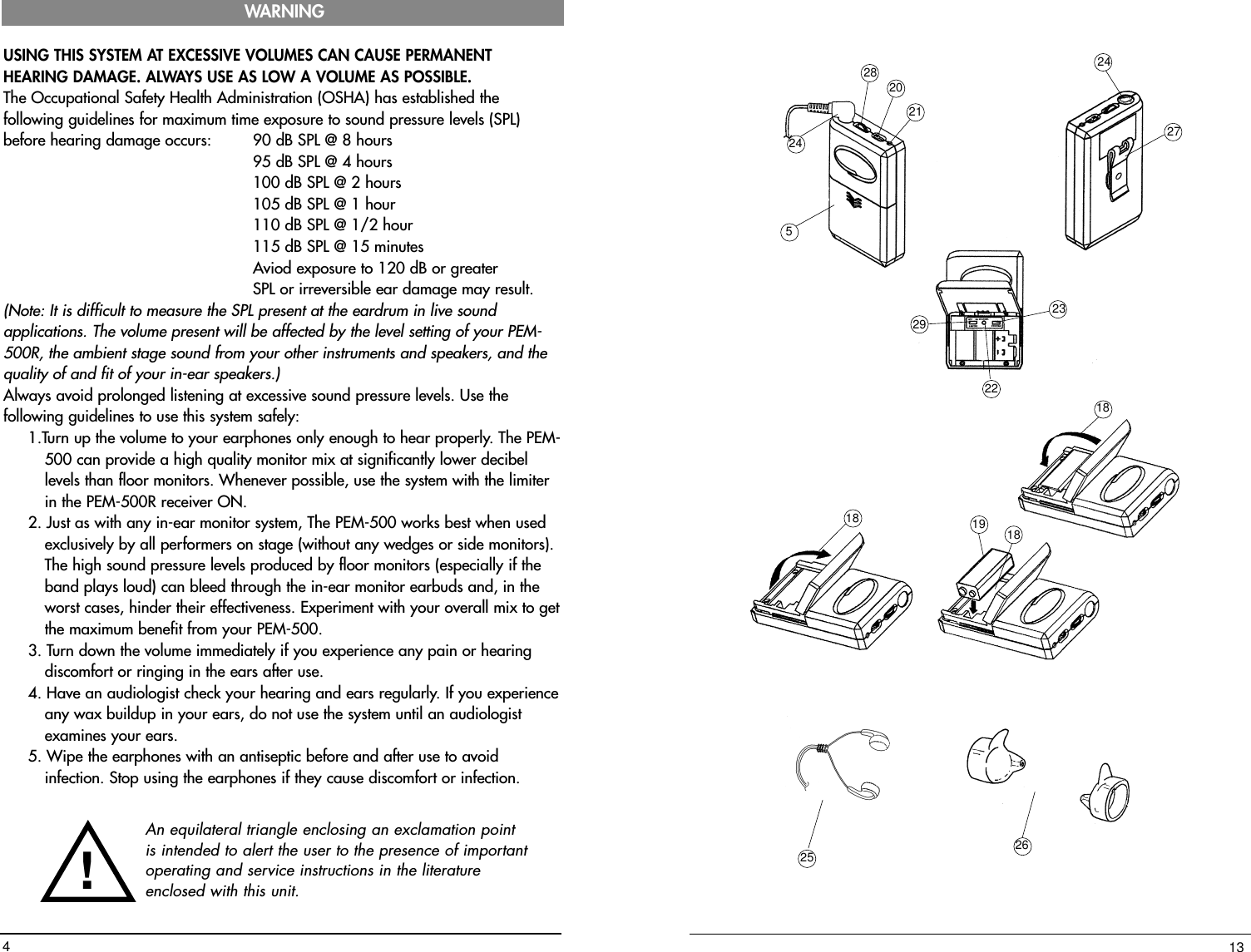

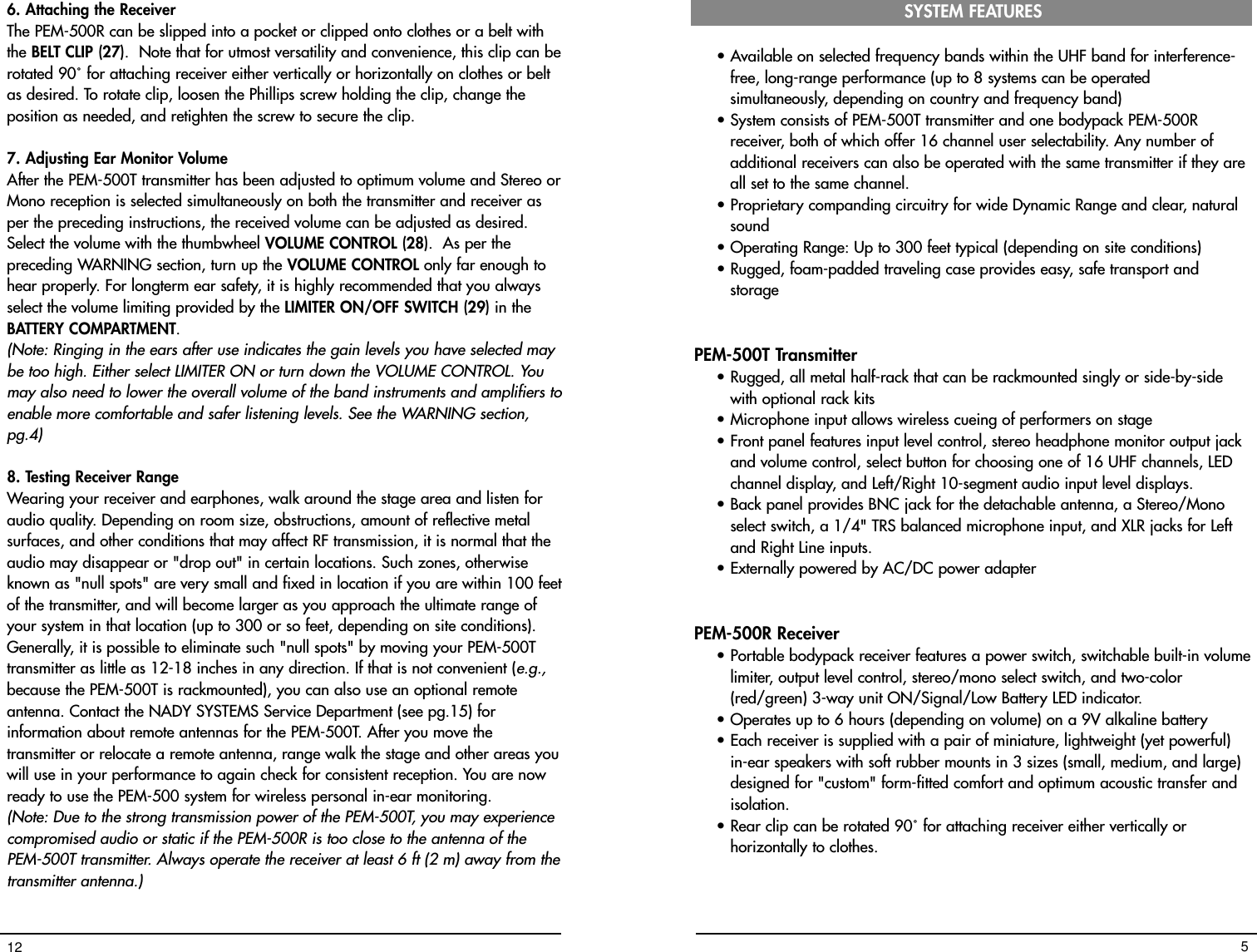
![4. Selecting Stereo or Mono Mode ReceptionSwitch the STEREO/MONO CONTROL (23) in the BATTERY COMPARTMENT tostereo or mono reception to match the transmission mode already selected for thetransmitter, as per the Connecting the Audio Input section of the PEM-500Ttransmitter instructions above. You can also try different combinations for differentapplications. For example, if multiple PEM-500R receivers are being used with onePEM-500T transmitting in stereo, the different performers may select either a stereomix with the STEREO/MONO CONTROL (which may feature vocals on one side andthe rest of the mix on the other), or a mono mix (with the vocals and music mixedtogether). Such capability adds to the versatility of the system by allowing morepersonal control of the individual sound received by different performers all listeningto the same transmitted mix. 5. Connecting the In-Ear Monitor Speakers The PEM-500R is provided with a 3.5 mm TRS STEREO EARPHONE MINI JACK (24)for connecting the EARBUD SPEAKERS (25) supplied. These miniature in-earspeakers can be inserted in the ear with the foam screens supplied as standardportable sound system earphones. For better isolation from ambient stage soundsand a more secure fit, 3 sets of soft "form-fit" RUBBER IN-EAR MOUNTS (26) areprovided to fit all sizes (small, medium and large). Select the size that best fits inyour ears most comfortably. Remove the foam screen from the earphones and slipthe RUBBER MOUNTS over each speaker. Insert the MOUNTS (with speakers), onein each ear. (Note: Wipe the earphones and rubber mounts with an antiseptic before and aftereach use to avoid infection. Stop using the earphones if they are causing discomfortor infection.)[Note: For best results and sound, a pair of custom-fitted ear transducers, suppliedwith soft rubber mounts cast by an audiologist from your own ear cavity, arerecommended. Although expensive, these earphones will provide the most natural,full frequency response, best acoustic isolation and longest-term wearing comfort.Such units can be ordered from suppliers such as Sensaphonics(www.sensaphonics.com) and Ultimate Ears (www.ultimateears.com). Contact one ofthese suppliers directly for more information on their custom earphones.] 11PEM-500T TRANSMITTER 1. Rackmounting the transmitterThe PEM-500T requires no installation and can be used on any flat surface.However, in some applications rack mounting is preferred. There are 2 optionsavailable for rackmounting the PEM-500T transmitter: singly or side-by-side withanother PEM-500T transmitter. • Single mounting: The PEM-500T is supplied with RE-5 RACK EARS (1) whichcan be attached with the screws provided on the front of the side panels toenable rackmounting the receiver.• Side-by-side dual mounting: Two PEM-500T transmitters can be rackmountedside-by-side using the optional RKT-25 RACK KIT TRAY (2) which holds 2transmitters. (Note: Do not mount the transmitter(s) in a rack directly above an amplifier or othersource of high heat–this could degrade the performance of the PEM-500T. Alwaysensure adequate airflow and heat dissipation in any rack configuration.)2. Powering the TransmitterPlug the 12V AC/DC ADAPTER (3) provided into the DC INPUT JACK (4) on theback of the receiver. Then plug the power supply into an AC outlet. (Note: Any 12-15V DC source with 500mA capability can also be used.) Press thePOWER SWITCH (5) once to turn on the transmitter. The POWER ON LED (6) willnow light and the transmitter is operational.3. AntennaConnect the front panel TELESCOPIC ANTENNA (7) or optional remote antenna tothe ANTENNA JACK (8). Extend the antenna fully to obtain maximum range.Optimal antenna position is vertical. For maximum range, it is always best tomaintain a line of sight (no obstructions) between the transmitter antenna and thereceiver(s) at all times whenever possible.OPERATION6](https://usermanual.wiki/SEIKAKU-TECHNICAL-GROUP/PEM-500T/User-Guide-180656-Page-7.png)
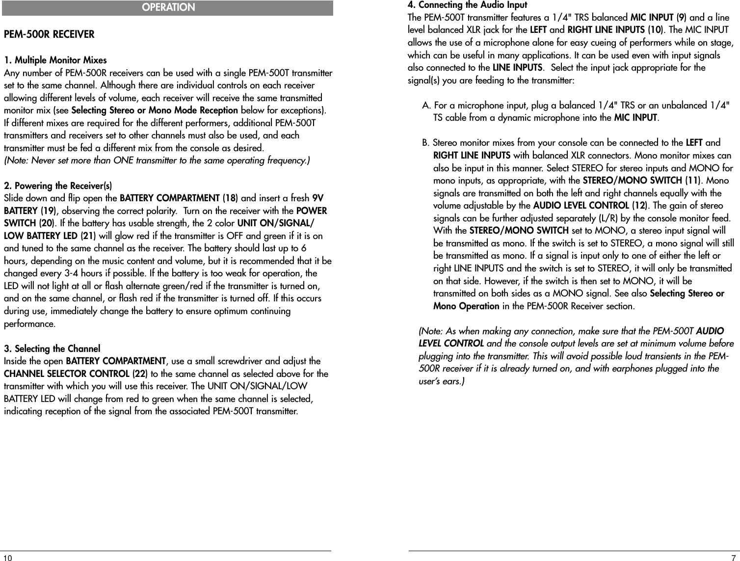
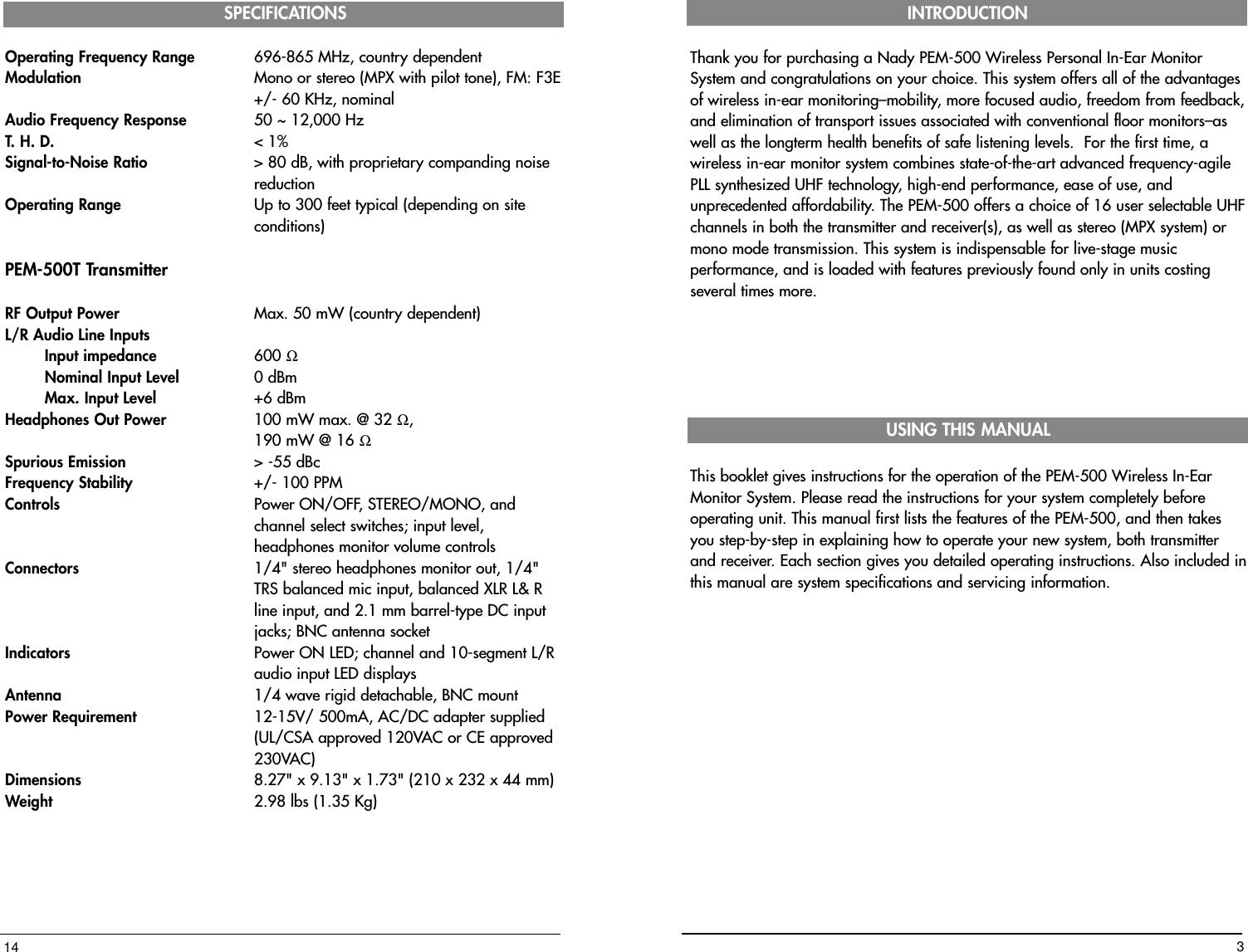
![12 15 14 13 17 16 6514110 11 9837295. Selecting a Channel/ Multiple System Operation Both the PEM-500T transmitter and PEM-500R receiver offer a choice of 16channels in the UHF band. Select an open frequency that doesn't interfere with anyother PEM-500 or UHF wireless mic system you are also using by pushing theCHANNEL SELECT BUTTON (13) on the front panel of the PEM-500T until thechannel you want is displayed on the CHANNEL LED DISPLAY (14). You will alsoneed to select the same channel for the transmitter (see Transmitter Operationinstructions above). If different mixes are required for the different performers,additional PEM-500T transmitters and receivers set to other channels must also beused, and each transmitter must be fed a different mix from the console as desired.Depending on the band(s) you are using and open channel availability within theband(s), up to 8 PEM-500 systems on different frequencies can be operatedsimultaneously to provide multiple discrete mixes to the performers.(Note: Never set more than ONE transmitter to the same operating frequency)[Note: After selecting a frequency on the transmitter, you must also check with thereceiver to ensure that the chosen channel is open (i.e., no other transmissions fromother sources, such as UHF TV channels in your area, operating at the samefrequency). Turn off the PEM-500T transmitter, and monitor the signal from the PEM-500R (see PEM-500R instructions, pg. 10). It should be silent. For optimumoperation and range, if you receive any transmissions or static you must chooseanother channel that is clear.][Note: If, after you complete the set-up, you experience interference orunsatisfactory audio performance, change the channel until the problem goes away.In the extremely rare circumstance that such a problem persists, turn off all UHFwireless mics being used or move their receivers physically away from the PEM-500T transmitter. In some instances, UHF wireless mics and the PEM-500 system caninteract if they are too close in frequency. Contact the NADY SYSTEMS ServiceDepartment for further information if necessary (see SERVICE, pg.15)]6. Adjusting Levels Adjust the selected audio input level for optimum level for transmission with theLEVEL CONTROL (12). Adjust the control so that the top LEDs on the 10-segment Leftand Right LED LEVEL DISPLAYS (15) light intermittently only on loud peaks. Thiscontrol adjusts both the left and right signals simultaneously in the same manner. Foradded control and separate levels on stereo inputs, use the left and right stereomonitor output level control on your console providing the signal.7.Headphone MonitoringThe sound technician can monitor the signal being transmitted with a wired pair ofheadphones via the stereo 1/4" TRS MONITOR OUTPUT JACK (16). The volumecan be adjusted as desired with the HEADPHONES VOLUME CONTROL (17). Boththe left and right channels of a stereo signal are adjusted simultaneously by thiscontrol in the same manner. 8](https://usermanual.wiki/SEIKAKU-TECHNICAL-GROUP/PEM-500T/User-Guide-180656-Page-9.png)
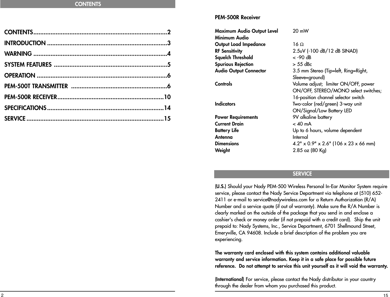
![12 15 14 13 17 16 6514110 11 9837295. Selecting a Channel/ Multiple System Operation Both the PEM-500T transmitter and PEM-500R receiver offer a choice of 16channels in the UHF band. Select an open frequency that doesn't interfere with anyother PEM-500 or UHF wireless mic system you are also using by pushing theCHANNEL SELECT BUTTON (13) on the front panel of the PEM-500T until thechannel you want is displayed on the CHANNEL LED DISPLAY (14). You will alsoneed to select the same channel for the transmitter (see Transmitter Operationinstructions above). If different mixes are required for the different performers,additional PEM-500T transmitters and receivers set to other channels must also beused, and each transmitter must be fed a different mix from the console as desired.Depending on the band(s) you are using and open channel availability within theband(s), up to 8 PEM-500 systems on different frequencies can be operatedsimultaneously to provide multiple discrete mixes to the performers.(Note: Never set more than ONE transmitter to the same operating frequency)[Note: After selecting a frequency on the transmitter, you must also check with thereceiver to ensure that the chosen channel is open (i.e., no other transmissions fromother sources, such as UHF TV channels in your area, operating at the samefrequency). Turn off the PEM-500T transmitter, and monitor the signal from the PEM-500R (see PEM-500R instructions, pg. 10). It should be silent. For optimumoperation and range, if you receive any transmissions or static you must chooseanother channel that is clear.][Note: If, after you complete the set-up, you experience interference orunsatisfactory audio performance, change the channel until the problem goes away.In the extremely rare circumstance that such a problem persists, turn off all UHFwireless mics being used or move their receivers physically away from the PEM-500T transmitter. In some instances, UHF wireless mics and the PEM-500 system caninteract if they are too close in frequency. Contact the NADY SYSTEMS ServiceDepartment for further information if necessary (see SERVICE, pg.15)]6. Adjusting Levels Adjust the selected audio input level for optimum level for transmission with theLEVEL CONTROL (12). Adjust the control so that the top LEDs on the 10-segment Leftand Right LED LEVEL DISPLAYS (15) light intermittently only on loud peaks. Thiscontrol adjusts both the left and right signals simultaneously in the same manner. Foradded control and separate levels on stereo inputs, use the left and right stereomonitor output level control on your console providing the signal.7.Headphone MonitoringThe sound technician can monitor the signal being transmitted with a wired pair ofheadphones via the stereo 1/4" TRS MONITOR OUTPUT JACK (16). The volumecan be adjusted as desired with the HEADPHONES VOLUME CONTROL (17). Boththe left and right channels of a stereo signal are adjusted simultaneously by thiscontrol in the same manner. 8](https://usermanual.wiki/SEIKAKU-TECHNICAL-GROUP/PEM-500T/User-Guide-180656-Page-10.png)

![4. Selecting Stereo or Mono Mode ReceptionSwitch the STEREO/MONO CONTROL (23) in the BATTERY COMPARTMENT tostereo or mono reception to match the transmission mode already selected for thetransmitter, as per the Connecting the Audio Input section of the PEM-500Ttransmitter instructions above. You can also try different combinations for differentapplications. For example, if multiple PEM-500R receivers are being used with onePEM-500T transmitting in stereo, the different performers may select either a stereomix with the STEREO/MONO CONTROL (which may feature vocals on one side andthe rest of the mix on the other), or a mono mix (with the vocals and music mixedtogether). Such capability adds to the versatility of the system by allowing morepersonal control of the individual sound received by different performers all listeningto the same transmitted mix. 5. Connecting the In-Ear Monitor Speakers The PEM-500R is provided with a 3.5 mm TRS STEREO EARPHONE MINI JACK (24)for connecting the EARBUD SPEAKERS (25) supplied. These miniature in-earspeakers can be inserted in the ear with the foam screens supplied as standardportable sound system earphones. For better isolation from ambient stage soundsand a more secure fit, 3 sets of soft "form-fit" RUBBER IN-EAR MOUNTS (26) areprovided to fit all sizes (small, medium and large). Select the size that best fits inyour ears most comfortably. Remove the foam screen from the earphones and slipthe RUBBER MOUNTS over each speaker. Insert the MOUNTS (with speakers), onein each ear. (Note: Wipe the earphones and rubber mounts with an antiseptic before and aftereach use to avoid infection. Stop using the earphones if they are causing discomfortor infection.)[Note: For best results and sound, a pair of custom-fitted ear transducers, suppliedwith soft rubber mounts cast by an audiologist from your own ear cavity, arerecommended. Although expensive, these earphones will provide the most natural,full frequency response, best acoustic isolation and longest-term wearing comfort.Such units can be ordered from suppliers such as Sensaphonics(www.sensaphonics.com) and Ultimate Ears (www.ultimateears.com). Contact one ofthese suppliers directly for more information on their custom earphones.] 11PEM-500T TRANSMITTER 1. Rackmounting the transmitterThe PEM-500T requires no installation and can be used on any flat surface.However, in some applications rack mounting is preferred. There are 2 optionsavailable for rackmounting the PEM-500T transmitter: singly or side-by-side withanother PEM-500T transmitter. • Single mounting: The PEM-500T is supplied with RE-5 RACK EARS (1) whichcan be attached with the screws provided on the front of the side panels toenable rackmounting the receiver.• Side-by-side dual mounting: Two PEM-500T transmitters can be rackmountedside-by-side using the optional RKT-25 RACK KIT TRAY (2) which holds 2transmitters. (Note: Do not mount the transmitter(s) in a rack directly above an amplifier or othersource of high heat–this could degrade the performance of the PEM-500T. Alwaysensure adequate airflow and heat dissipation in any rack configuration.)2. Powering the TransmitterPlug the 12V AC/DC ADAPTER (3) provided into the DC INPUT JACK (4) on theback of the receiver. Then plug the power supply into an AC outlet. (Note: Any 12-15V DC source with 500mA capability can also be used.) Press thePOWER SWITCH (5) once to turn on the transmitter. The POWER ON LED (6) willnow light and the transmitter is operational.3. AntennaConnect the front panel TELESCOPIC ANTENNA (7) or optional remote antenna tothe ANTENNA JACK (8). Extend the antenna fully to obtain maximum range.Optimal antenna position is vertical. For maximum range, it is always best tomaintain a line of sight (no obstructions) between the transmitter antenna and thereceiver(s) at all times whenever possible.OPERATION6](https://usermanual.wiki/SEIKAKU-TECHNICAL-GROUP/PEM-500T/User-Guide-180656-Page-12.png)