SEIKAKU TECHNICAL GROUP TMWU-100BP UHF Wireless Microphone Transmitter User Manual

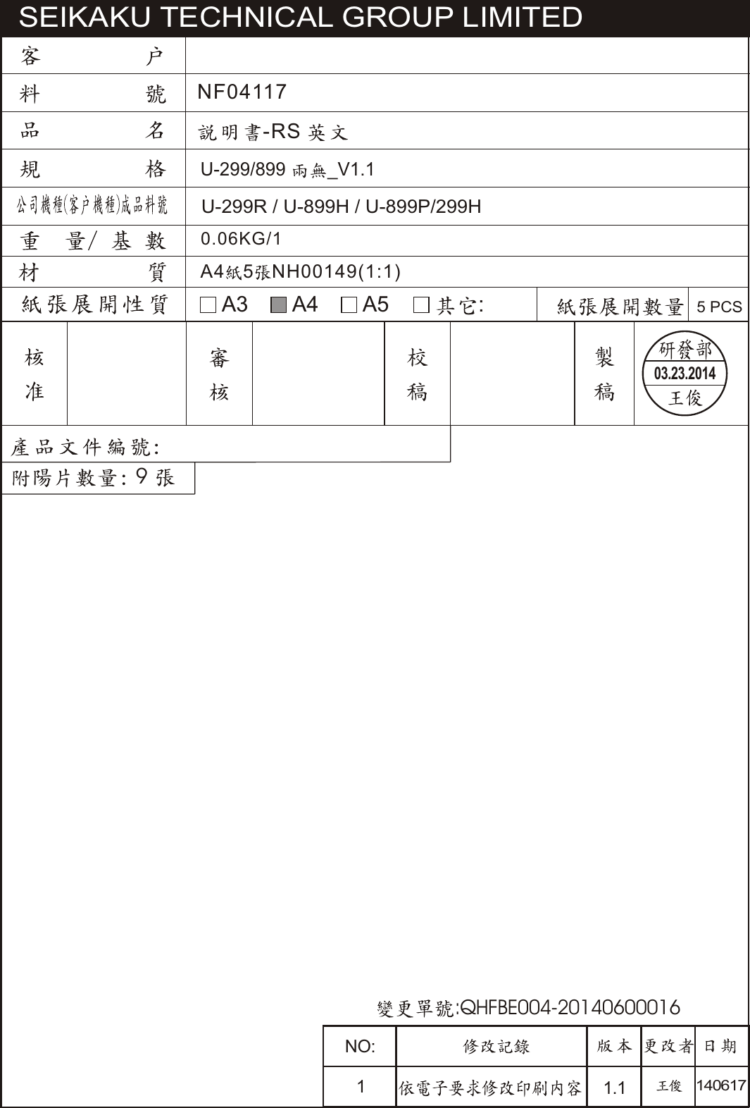
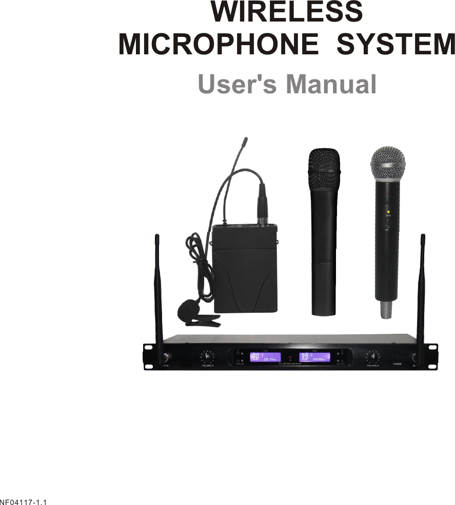
SEIKAKU TECHNICAL GROUP LIMITED UHF Wireless Microphone Transmitter

user manual

-RS 0.06KG/1SEIKAKU TECHNICAL GROUP LIMITED                  9 A4 5 NH00149(1:1)A3 A4U-299/899 _V1.1A5 :5 PCSU-299R / U-899H / U-899P/299H03.23.2014NF04117NO:11.1140617:QHFBE004-20140600016
User's ManualWIRELESS MICROPHONE  SYSTEMNF04117-1.1
INDEXSAFETY RELATED SYMBOLS WARNINGIMPORTANT SAFETY INSTRUCTIONSINTRODUCTIONCONTROL ELEMENTSOPERATING INSTRUCTIONTECHNICAL SPECIFICATIONS0102030405060711234~89~1212~15Table of Contents15CHB:470-566 MHz CHANNEL TABLE(USA)WIRELESS  MIC  SYSTEM Channel Plans
SAFETY RELATED SYMBOLS CAUTIONRISK OF ELECTRIC SHOCKDO NOT OPENThe symbol is used to indicate that some hazardous live terminals are involved within this apparatus, even under the normal operating conditions.The symbol is used in the  service documentation to indicate that specific component shall be only replaced by the component specified in that Documentation for safety reasons.Protective grounding terminal.Alternating current /voltage.ON:  Denotes the apparatus turns on.OFF:  Denotes the apparatus turns off, bec-ause of using the single pole switch, be sure to unplug the AC power to prevent any electric shock before you proceed your service.WARNING:  Describes precautions that should be observed to prevent the danger of injury or death to the user.CAUTION:  Describes precautions that should be observed to prevent danger of the apparatus.WARNINGPower Supply Ensure the source voltage matches the voltage of the power supply before turning ON the apparatus.Unplug  this  apparatus  during  lightning storms  or  when  unused  for  long  periods of time.External Connection The external wiring connected to the output hazardous live terminals requires installation by an instructed person, or the use of ready-made leads or cords.Do not Remove any Cover There  are  maybe  some  areas  with  high voltages inside, to reduce the risk of electric shock, do not remove any cover if the power supply is connected. The cover should be removed by the qualified personnel only. No user serviceable parts inside.Fuse To  prevent  a  fire,  make  sure  to  use  fuses with   specified   standard  (current,   voltage, type).  Do not  use  a  different  fuse or  shortcircuit the fuse holder. Before  replacing  the  fuse,  turn  OFF the apparatus and disconnected the power source.Protective Grounding Make   sure   to   connect   the   protective grounding   to   prevent   any   electric  shock before turning ON the apparatus. Never  cut off the internal or external pro-tective  grounding  wire  or  disconnect  the wiring of protective grounding terminal. Operating ConditionsHazardous live terminal .Disposing of this product should not be placed in municipal waste and should be separate collection.This   apparatus   shall   not   be   exposed  to dripping  or  splashing  and  that  no  objects filled  with  liquids,  such  as  vases,  shall  be placed on this apparatus.1CHA:470-566 MHz CHANNEL TABLE(USA)14WIRELESS  MIC  SYSTEM Channel Plans
ServicingRefer all servicing to qualified personnel.  To reduce   the  risk  of  electric  shock,  do  not perform   any   servicing   other   than   that contained in the operating instructions unless you are qualified to do so .Servicing is required wh en the apparatus has been  damaged  in  any  way , such  as  power supply  cord  or  plug  is  damaged , liquid has been spilled or  objects have fallen into the apparatus,  the apparatus has been exposed to   rain   or   moisture ,   does   not   operate normally, or has been dropped.To reduce the risk of fire or electric shock, do not expose this apparatus to rain or moisture. Do   not   use   this   apparatus   near   water.Install in accordance with the manufacture-r's instructions.  Do  not  install  near  any  heat sources  such  as  radiators,  heat  registers, stoves,  or  other  apparatus  (including  am-plifiers)  that  produce  heat.  Do  not  block any ventilation openings. IMPORTANT SAFETY INSTRUCTIONS Read these instructions.Keep these instructions.Heed all warnings.Only use attachments/accessories spec-   ified by the manufacturer.Power Cord and PlugDo not defeat the safety purpose of the polarized or grounding type plug. A   polarized   plug   has   two   blades   with one   wider   than   the   other.  A   grounding type   plug   has   two   blades   and   a   third grounding  prong.  The  wide  blade  or  the third  prong  are  provided  for  your  safety. If the provided plug does not fit into your outlet,  consult  an  electrician  for  replace-ment of the obsolete outlet.Protect  the  power  cord  from  being  walk-ed   on   or   pinched   particularly   at   plugs, convenience  receptacles,   and  the   point where they exit from the apparatus.Cleaning When the apparatus needs a cleaning, you can blow off dust from the apparatus with Follow all instructions.No naked flame sources, such as lighted candles, should be placed on the apparatus.a blower or clean with rag etc. Don't use solvents such as benzol, alcohol, or other fluids with very strong volatility and flammability for cleaning the apparatus body. Clean only with dry cloth.The mains plug is used as the disconnect device,the disconnect device shall remain readily operable.Changes  or  modifications   to  this  unit   not expressly approved by the  party  responsiblefor compliance could void the user's authorityto operate the equipment.NOTE: This equipment has been tested and found to comply  with the  limits for  a  class  Bdigital device, pursuant to Part 15 of the FCCRules .These  limits  are  designed  to  provide  reasonable     protection      against     harmfulinterference in a residential  installation . This equipment  generates,  uses  and  can  radiate radio  frequency  energy  and ,  if  not  installed  MARKUS wireless receivers are certified under FCCRules part 15 and transmitters are  certified under FCC Rules part 74.Licensing of MARKUS  equipment is the user's responsibility and licensability dependson the user's classification, application  and  frequency selected.  FCC Rules and Regulations213TECHNICAL SPECIFICATIONSTone frequncy WeightDynamicMic / Instrument InputMicrophone CapsuleBatteryOperating TemperatureDimensionsCurrent drainFrequency responseT.H.DFrequency stabilityModulation modeOscillation modeCarrier frequency bandMODELSpecificationSpurious EmissionRF  R adiation C ERF R adiation Fcc4 band choiceBeltpack micUHFPLL UHF SYNTHESIZEDFM(F3E)0.005%100dB10dBu"AA" typex2pcs(used for more than 6 hours)150mA50Hz-15KHz( 3dB)1.0%10mW50dBm35KHz65x85x25mm0.082Kg00-10 C to 50 C2.Power supply4. Dynamic or condenser Mic3. Electric instrument1. GroundCondenser Dynamic CapsuleMetal/Plastic hand mic UHFPLL UHF SYNTHESIZEDFM(F3E)0.005%100dB10dBu0.3kg/0.27Kg(Approx.)260* 36mm/240* 50mmDynamic Capsule"AA" typex2pcs(used for more than 6 hours)150mA50Hz-15KHz( 3dB)1.0%10mW50dBm35KHz00-10 C to 50 CTRANSMITTER
and used in accordance with the instructions,may cause harmful interference to radio communications. However, there is no  guarantee that interference will not occur in a particular installation. If this equipment does cause harmful interferenceto radio or television reception, whichcan be determined by turning theequipment off and on, the user isencouraged to try to correct the interference by one or more of the following measures:  --Reorient or relocate the receiving antenna.--Increase    the   separation    between    theequipment and receiver.--Connect the equipment into an outlet on acircuit  different  from   that   to   which   the receiver is connected.--Consult the dealer or an experienced radio/TV technician for help.This device complies with Part 15 of the FCCRules. Operation  is  subject  to  the  followingtwo conditions:(1) this device may not  causeharmful interference and (2) this device must accept  any  interference  received.  includinginterference    that    may    cause    undesired operation.INTRODUCTIONHereby, Seikaku Technical Group Limited,declares that this wireless microphone system is in compliance with the essentialrequirements and other relevant provisionsof Directive 1999/5/EC. FEATURES336677Wisdom ID recognition technology,200pcs Mic using separately.Disital mode mix transmit,audio22Infrared(IR)synchronization technique.Transmitter battery:Two 1.5V,convenience Operation.The balance and the non-balanced audio frequency transmitter output,connect e  achkind of acoustic equipment easily.Transmitter red candle twinkle instruction,adapt the humannity  visual c  haracteristic.3Thanks for purchasing the wireless microphone system.This system is the delicately designedUHF, PLL synthesized system.with dual channel wireless receiver and applications with twomicrophones   open si multaneo us ly.Adap ted to vari ous condi tion, specially KTV.un-digital transfer disadvantage for delay.Different ID identification number for each  frequency point, to prevent mutual interference between each frequency point.445512OPERATING INSTRUCTIONTurn on your connected amplifier or mixer, but keep the volume all the way down. Set the Volume knob on the receiver fully clockwise.This is unity gain.Speak or sing into the microphone,or if you are using the transmitter with a connected instrument,play the instrument at normal performance level. Slowly raise the volume of your amplifier or mixer until the desired level is reached.If you find the system has noticeable dropouts,reduced overall working range,or unexpected noise bursts,change the operating channel of the system using the steps above.TECHNICAL SPECIFICATIONSRECEIVERChannelReceiver typeFrequency band          UHFChannelDual-channels, up to 100 frequency presetsf or each f requency b  andsDual Receiver and PLL UHF SYNTHESIZED Frequency response    50Hz-15KHz( 3dB)Frequency stability       0.005%Modulation mode        FM(F3E)T.H.D                           1%Dynamic                       100dBMax Unbalanced Output    1 0dBuMax Balanced Output   1  0dBuS/N Ratio                     100 dBRF sensitivity               -100dbm/30db Power supply               1 00-240V/50~60Hz_DC12V/500mA                            Dimensions                  4  5  (W) 200(H) 480(L) m mWeight                          3  . 5Kg(Approx.)Display mode              LCD displayUPDOWN / PAIRIRCH A CH BPLL UHF DUAL RECEIVERUPDOWN / PAIRU-299RANT.A VOLUME.A VOLUME.B POWER ANT.BLCD screen display transmitter battery and RF/AF signal peak display200 sets of intelligent recognition ID for interference preventionBalanced and unbalanced audio frequency transmitter output88
5566778899  CHB LCD Screen  CHB Operation button  CHB adjust the volume knod  Power button/LockAntenna port11223344  CHA adjust the volume knod  CHA Operation button  CHA LCD Screen  Infrarde(IR)UPDOWN / PAIRIRCH A CH BPLL UHF DUAL RECEIVERUPDOWN / PAIRANT.A VOLUME.A VOLUME.B POWER ANT.B112233445566778899FRONT PANELReceiver11  CHB audio  XLR  balanced output2233  Adapter jack44  Mix audio frequency  Squel CHB  CHA audio XLR   balanced  output55  Squel CHA661122334455664CONTROL ELEMENTSBack PanelOPERATING INSTRUCTIONPosition the transmitter about 15~30cm from the front of the receiver with the  transmitter s IR window facing the IR transmitter on the front panel of the  receiver.Press and hold the receiver UP/DOWN  button to set the transmitter to t he s ame c hannel a s t here ceiver vi a in frared tr ansmission.When the transmission is complete, the receiver will receive RF signal and tone key from the transmitter. The RF indicator of the screen will light on the front panel of the  receiver.,UPDOWN / PAIRIRCH A CH BPLL UHF DUAL RECEIVERUPDOWN / PAIRANT.A VOLUME.A VOLUME.B POWER ANT.BUPDOWN / PAIRIRCH A CH BPLL UHF DUAL RECEIVERUPDOWN / PAIRANT.A VOLUME.A VOLUME.B POWER ANT.B11
5CONTROL ELEMENTSReceiver screenReceiver power on1111223344  Mic power display, power  flashing the power Failure5566  Frequency  displayRFpower indicationAFpower indication Mic Mute  indication2233445566  Frequency  code10OPERATING INSTRUCTIONWith the transmitter powered off, install two fresh AA batteries into the MIC .Leave the battery compartment open.Turn on the power to the transmitter by pressing and holding Power swith; the indicator LED will light green.Press the UP/DOWN  button on the front of the  receiver to choose an availablechannel.The channel number will increase by two digit,from 00-99.Once the last channel has been reached, the count will cycle back to 00.Press and hold the UP/DOWN button for 2 seconds to send the channel information to the transmitter via infrared transmission.Press and hold the UP button the display channel will be fast forward.UPDOWN / PAIRIRCH A CH BPLL UHF DUAL RECEIVERUPDOWN / PAIRANT.A VOLUME.A VOLUME.B POWER ANT.BPress and hold the DOWN button the display channel will be fast backward.7777  Button lock indication113344Press the receiver power button continually.Receiver power on, after 2 secondsdisplay frequency and r eady.Receiver p ower o n,press a nd r elease t he p ower b utton t o l ock/unlock t he U  P/DOWN b utton.Press the receiver power button again continually,after 2 seconds have no frequency code display,then loosen your hand,receiver power off.If long time does not use the receiver,pls pull out the power adapter from the power jack.22
123123SQUELCH BMIN MAXSQUELCH AMIN MAX CH BCH AS/NMODEL1122336CONTROL ELEMENTS66Power/Mute Switch55IR Receiving Section This window is used to capture the infrared signal sent from the receiver during the IR UP/DOWN  to  channelize the transmitter.44Status IndicatorThis LED displays the operation mode:Tail tube33PLASTIC HAND MICGrille Holder1122 TubeGREENREDFlashing REDNormal OperationMuteLow Battery554466METAL HANG MICGREENREDFlashing REDNormal OperationMuteLow BatteryStatus indicator11This LED displays the operation mode:Power/Mute Switch22Battery Cover33Unscrew the battery cover and slide down to open the   MIC   battery  compartmentOPERATING INSTRUCTIONIn order for your wireless system to work correctly,both the receiver and transmitter must be set to the same channel.With your amplifier or mixer off and volume control all the way down:connect the  receiver output jack to the mic or line level input of a mixer or amplifier using the balanced XLR output or unbalanced 1/4" line level output.Turn the Level knob on the  receiver completely counterclockwise, then turn its power on.Follow the basic procedure for setting up and using your receiver wrieless system:Physically place the  receiver where it will be used,and extend the antennas vertically. With the Power switch on and  receiver power off,connect the included power adapter.Turn the  receiver on momentarily to confirm that the unit is receiving power. You will see the LCD display light up. Then turn  receiver power off.9UPDOWN / PAIRIRCH A CH BPLL UHF DUAL RECEIVERUPDOWN / PAIRU-299RANT.A VOLUME.A VOLUME.B POWER ANT.B             Press and hold to turn the unit on or off. Press and release to mute or unmute the transmitter.             Press and hold to turn the unit on or off. Press and release to mute or unmute the transmitter.
Power/Mute Switch33BELTPACK MICAntenna1122 Status IndicatorThis permanently attached transmitter antenna should be fully extended during normal operation.This LED displays the operation mode:GREENREDFlashing REDNormal OperationMuteLow BatteryCONTROL ELEMENTS7Battery Holder44Open the battery holder by pressing the tab and lifting the cover.insert two standard AA(LR6)batteries here,being sure to observe the plus and minus polarity markings shown.Although rechargeable Ni-Cad batteries can be used,they do not supply adequate current for more than four hours.WARNING:Do not insert the batteries backwards;doing so can cause severe damage to the MIC  and will void your warranty.Input GAIN Control55This control adjusts the transmitter input sensitivity.For optimal performance, using  the  includedscrewdriver,IR Lens66This w  indow i s u  sed t o c apture t he i nfrared s ignal s ent f rom t he d  u  ring th e IR  U P/DOWN t o c  hannelize t he t ransmitter.The b  attery c  over m  ust b  e o  pen a  nd t he I R L  ens f acing t owards t he receiver to load the selected channel.receiver  Plastic Screwdriver77Designed for use in adjusting the MIC  input GAIN control(See #5 Input GAIN Control HH).Set the input GAIN control to where you can see the RF display of receiverscreen become to  fulllight, the  n turn do  wn u  ntil  the RF  displ  ay n  ot  full light  (les  sth anfive).    Input GAIN ControlThis control adjusts the transmitter input sensitivity to work with microphone and instruments inputs.For optimal performance,using the included screwdriver,66  DriverDesigned for use in adjusting the MIC input GAIN control.77IR Receiving SectionThis window is used to capture the infrared  signal sent from the receiver during the IR  UP/DOWN to channelize the transmitter.5544MINI 4P CONNECTORCONTROL ELEMENTS8Pin 1, GNDPin 4, for Dynamic or condenser microphonePin 2, Phantom power supply for Condenser microphonePin 3, for Guitar, bass and keyboardsAABBCCDDBBCCAADD4411332277665511Set the  input GAIN  controlt  owhere you can see the RF display of U-299R screen become to full light , th en tu rn  dow n                      until the T he reforedisplay not full light(less than five).                Press and hold to turn the unit on or off. Press and release to mute or unmute the transmitter.receiver

Navigation menu