SEIKAKU TECHNICAL GROUP U-299H UHF Wireless Microphone User Manual
SEIKAKU TECHNICAL GROUP LIMITED UHF Wireless Microphone
user manual
-RS
0.06KG/1
SEIKAKU TECHNICAL GROUP LIMITED
9
A4 5 NH00149(1:1)
A3 A4
U-299/899 _V1.1
A5 :
5 PCS
U-299R / U-899H / U-899P/299H
03.23.2014
NF04117
NO:
11.1
140617
:QHFBE004-20140600016
User's Manual
WIRELESS
MICROPHONE SYSTEM
NF04117-1.1
INDEX
SAFETY RELATED SYMBOLS
WARNING
IMPORTANT SAFETY INSTRUCTIONS
INTRODUCTION
CONTROL ELEMENTS
OPERATING INSTRUCTION
TECHNICAL SPECIFICATIONS
01
02
03
04
05
06
07
1
1
2
3
4~8
9~12
12~15
Table of Contents
15
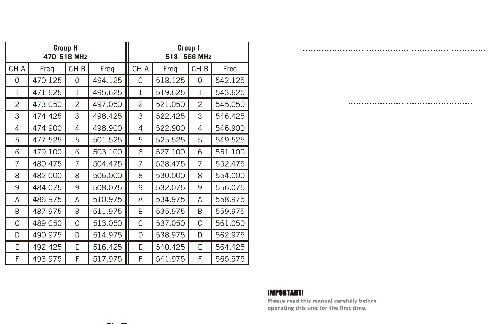
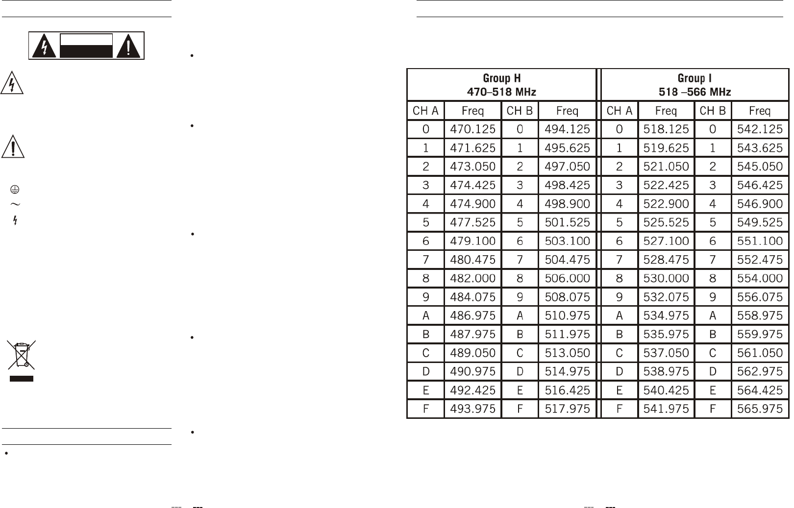
CHB:470-566 MHz CHANNEL TABLE(USA)
WIRELESS MIC SYSTEM Channel Plans
SAFETY RELATED SYMBOLS
CAUTION
RISK OF ELECTRIC SHOCK
DO NOT OPEN
The symbol is used to indicate that
some hazardous live terminals are
involved within this apparatus, even
under the normal operating conditions.
The symbol is used in the service
documentation to indicate that specific
component shall be only replaced by
the component specified in that
Documentation for safety reasons.
Protective grounding terminal.
Alternating current /voltage.
ON: Denotes the apparatus turns on.
OFF: Denotes the apparatus turns off, bec-
ause of using the single pole switch, be sure
to unplug the AC power to prevent any
electric shock before you proceed your
service.
WARNING: Describes precautions that
should be observed to prevent the danger
of injury or death to the user.
CAUTION: Describes precautions that
should be observed to prevent danger of the
apparatus.
WARNING
Power Supply
Ensure the source voltage matches the
voltage of the power supply before turning
ON the apparatus.
Unplug this apparatus during lightning
storms or when unused for long periods
of time.
External Connection
The external wiring connected to the output
hazardous live terminals requires installation
by an instructed person, or the use of ready-
made leads or cords.
Do not Remove any Cover
There are maybe some areas with high
voltages inside, to reduce the risk of electric
shock, do not remove any cover if the power
supply is connected.
The cover should be removed by the qualified
personnel only.
No user serviceable parts inside.
Fuse
To prevent a fire, make sure to use fuses
with specified standard (current, voltage,
type). Do not use a different fuse or short
circuit the fuse holder.
Before replacing the fuse, turn OFF the
apparatus and disconnected the power
source.
Protective Grounding
Make sure to connect the protective
grounding to prevent any electric shock
before turning ON the apparatus.
Never cut off the internal or external pro-
tective grounding wire or disconnect the
wiring of protective grounding terminal.
Operating Conditions
Hazardous live terminal .
Disposing of this product should
not be placed in municipal waste
and should be separate collection.
This apparatus shall not be exposed to
dripping or splashing and that no objects
filled with liquids, such as vases, shall be
placed on this apparatus.
1
CHA:470-566 MHz CHANNEL TABLE(EU&USA)
14
WIRELESS MIC SYSTEM Channel Plans
Servicing
Refer all servicing to qualified personnel. To
reduce the risk of electric shock, do not
perform any servicing other than that
contained in the operating instructions unless
you are qualified to do so .
Servicing is required wh en the apparatus has
been damaged in any way , such as power
supply cord or plug is damaged , liquid has
been spilled or objects have fallen into the
apparatus, the apparatus has been exposed
to rain or moisture , does not operate
normally, or has been dropped.
To reduce the risk of fire or electric shock,
do not expose this apparatus to rain or
moisture.
Do not use this apparatus near water.
Install in accordance with the manufacture-r's
instructions. Do not install near any heat
sources such as radiators, heat registers,
stoves, or other apparatus (including am-
plifiers) that produce heat. Do not block
any ventilation openings.
IMPORTANT SAFETY INSTRUCTIONS
Read these instructions.
Keep these instructions.
Heed all warnings.
Only use attachments/accessories spec-
ified by the manufacturer.
Power Cord and Plug
Do not defeat the safety purpose of the
polarized or grounding type plug.
A polarized plug has two blades with
one wider than the other. A grounding
type plug has two blades and a third
grounding prong. The wide blade or the
third prong are provided for your safety.
If the provided plug does not fit into your
outlet, consult an electrician for replace-
ment of the obsolete outlet.
Protect the power cord from being walk-
ed on or pinched particularly at plugs,
convenience receptacles, and the point
where they exit from the apparatus.
Cleaning
When the apparatus needs a cleaning, you
can blow off dust from the apparatus with
Follow all instructions.
No naked flame sources, such as lighted
candles, should be placed on the apparatus.
a blower or clean with rag etc.
Don't use solvents such as benzol, alcohol,
or other fluids with very strong volatility and
flammability for cleaning the apparatus body.
Clean only with dry cloth.
The mains plug is used as the disconnect device,
the disconnect device shall remain readily
operable.
Changes or modifications to this unit not
expressly approved by the party responsible
for compliance could void the user's authority
to operate the equipment.
NOTE: This equipment has been tested and
found to comply with the limits for a class B
digital device, pursuant to Part 15 of the FCC
Rules .These limits are designed to provide
reasonable protection against harmful
interference in a residential installation . This
equipment generates, uses and can radiate
radio frequency energy and , if not installed
MARKUS wireless receivers are certified under FCC
Rules part 15 and transmitters are certified under
FCC Rules part 74.Licensing of MARKUS equipment
is the user's responsibility and licensability depends
on the user's classification, application and frequency
selected.
FCC Rules and Regulations
213
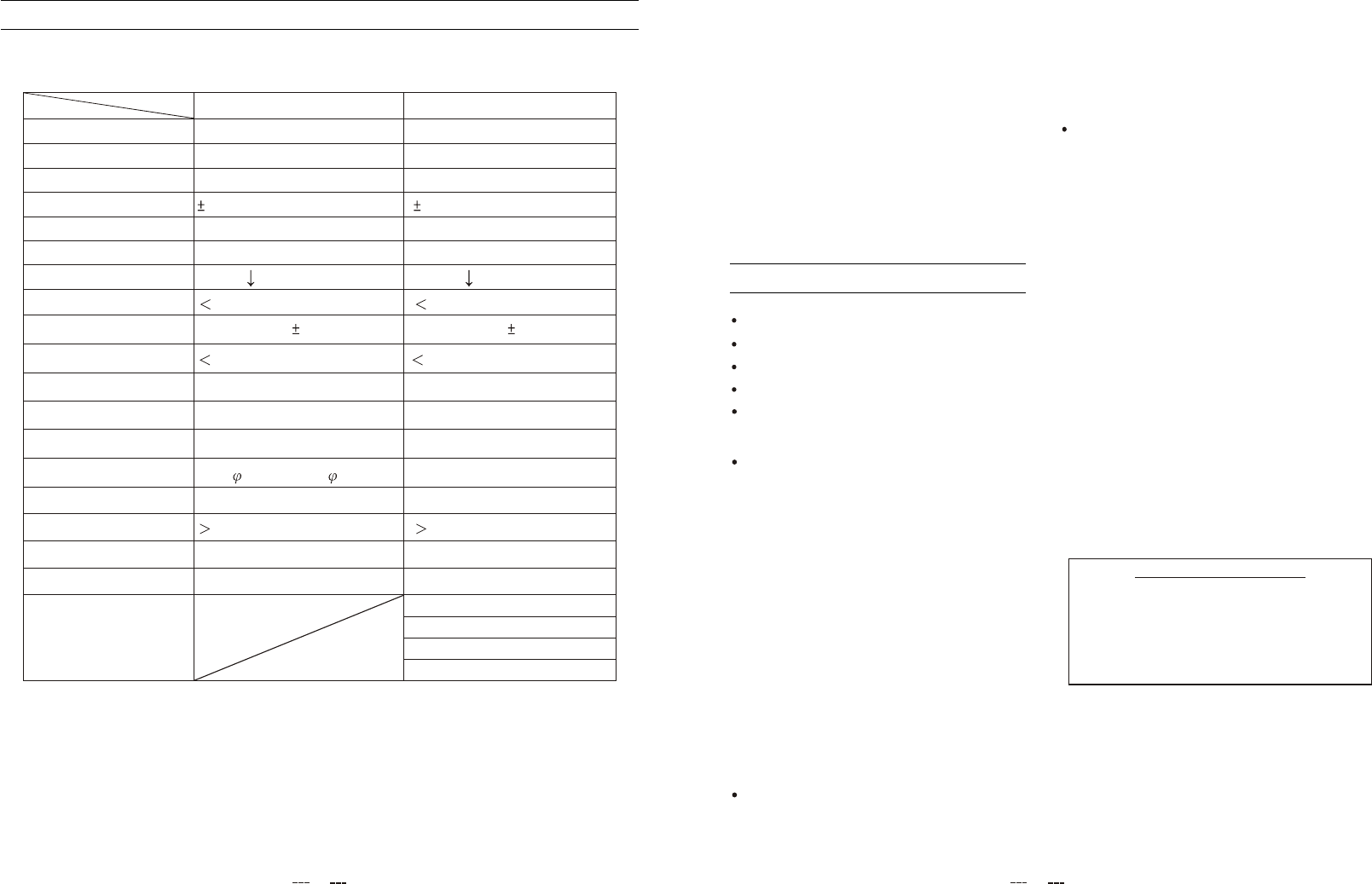
TECHNICAL SPECIFICATIONS
Tone frequncy
Weight
Dynamic
Mic / Instrument Input
Microphone Capsule
Battery
Operating Temperature
Dimensions
Current drain
Frequency response
T.H.D
Frequency stability
Modulation mode
Oscillation mode
Carrier frequency band
MODEL
Specification
Spurious Emission
RF R adiation C E
RF R adiation Fcc
4 band choice
Beltpack mic
UHF
PLL UHF SYNTHESIZED
FM(F3E)
0.005%
100dB
10dBu
"AA" typex2pcs
(used for more than 6 hours)
150mA
50Hz-15KHz( 3dB)
1.0%
10mW
50dBm
35KHz
65x85x25mm
0.082Kg
00
-10 C to 50 C
2.Power supply
4. Dynamic or condenser Mic
3. Electric instrument
1. Ground
Condenser Dynamic Capsule
Metal/Plastic hand mic
UHF
PLL UHF SYNTHESIZED
FM(F3E)
0.005%
100dB
10dBu
0.3kg/0.27Kg(Approx.)
260* 36mm/240* 50mm
Dynamic Capsule
"AA" typex2pcs
(used for more than 6 hours)
150mA
50Hz-15KHz( 3dB)
1.0%
10mW
50dBm
35KHz
00
-10 C to 50 C
TRANSMITTER
and used in accordance with the instructions,
may cause harmful interference to radio
communications. However, there is no
guarantee that interference will not occur in
a particular installation. If this
equipment does cause harmful interference
to radio or television reception, which
can be determined by turning the
equipment off and on, the user is
encouraged to try to correct the
interference by one or more of the following
measures:
--Reorient or relocate the receiving antenna.
--Increase the separation between the
equipment and receiver.
--Connect the equipment into an outlet on a
circuit different from that to which the
receiver is connected.
--Consult the dealer or an experienced radio/
TV technician for help.
This device complies with Part 15 of the FCC
Rules. Operation is subject to the following
two conditions:(1) this device may not cause
harmful interference and (2) this device must
accept any interference received. including
interference that may cause undesired
operation.
INTRODUCTION
Hereby, Seikaku Technical Group Limited,
declares that this wireless microphone
system is in compliance with the essential
requirements and other relevant provisions
of Directive 1999/5/EC.
FEATURES
33
66
77
Wisdom ID recognition technology,200pcs Mic using separately.Disital mode mix transmit,audio
22Infrared(IR)synchronization technique.
Transmitter battery:Two 1.5V,convenience Operation.
The balance and the non-balanced audio frequency transmitter output,connect e ach
kind of acoustic equipment easily.
Transmitter red candle twinkle instruction,adapt the humannity visual c haracteristic.
3
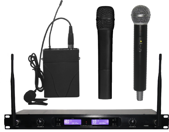
Thanks for purchasing the wireless microphone system.This system is the delicately designed
UHF, PLL synthesized system.with dual channel wireless receiver and applications with two
microphones
open si multaneo us ly.Adap ted to vari ous condi tion, specially KTV.
un-digital transfer disadvantage for delay.Different ID identification number for each
frequency point, to prevent mutual interference between each frequency point.
44
55
12
OPERATING INSTRUCTION
Turn on your connected amplifier or mixer, but keep the volume all the way down. Set the Volume knob
on the receiver fully clockwise.This is unity gain.
Speak or sing into the microphone,or if you are using the transmitter with a connected instrument,play
the instrument at normal performance level. Slowly raise the volume of your amplifier or mixer until the
desired level is reached.
If you find the system has noticeable dropouts,reduced overall working range,or unexpected noise bursts,
change the operating channel of the system using the steps above.
TECHNICAL SPECIFICATIONS
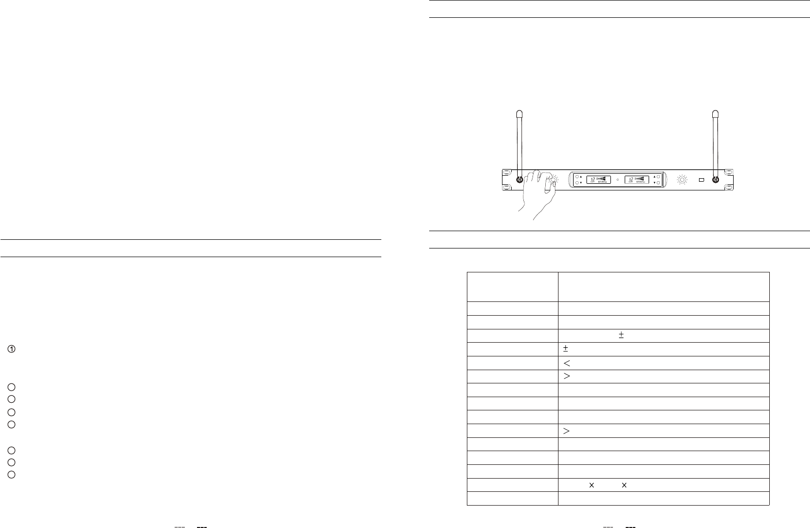
RECEIVER
Channel
Receiver type
Frequency band UHF
ChannelDual-channels, up to 100 frequency presets
f or each f requency b ands
Dual Receiver and PLL UHF SYNTHESIZED
Frequency response 50Hz-15KHz( 3dB)
Frequency stability 0.005%
Modulation mode FM(F3E)
T.H.D 1%
Dynamic 100dB
Max Unbalanced Output 1 0dBu
Max Balanced Output 1 0dBu
S/N Ratio 100 dB
RF sensitivity -100dbm/30db
Power supply 1 00-240V/50~60Hz_DC12V/500mA
Dimensions 4 5 (W) 200(H) 480(L) m m
Weight 3 . 5Kg(Approx.)
Display mode LCD display
UP
DOWN / PAIR
IR
CH A CH B
PLL UHF DUAL RECEIVER
UP
DOWN / PAIR
U-299R
ANT.A VOLUME.A VOLUME.B POWER ANT.B
LCD screen display transmitter battery and RF/AF signal peak display
200 sets of intelligent recognition ID for interference prevention
Balanced and unbalanced audio frequency transmitter output
88
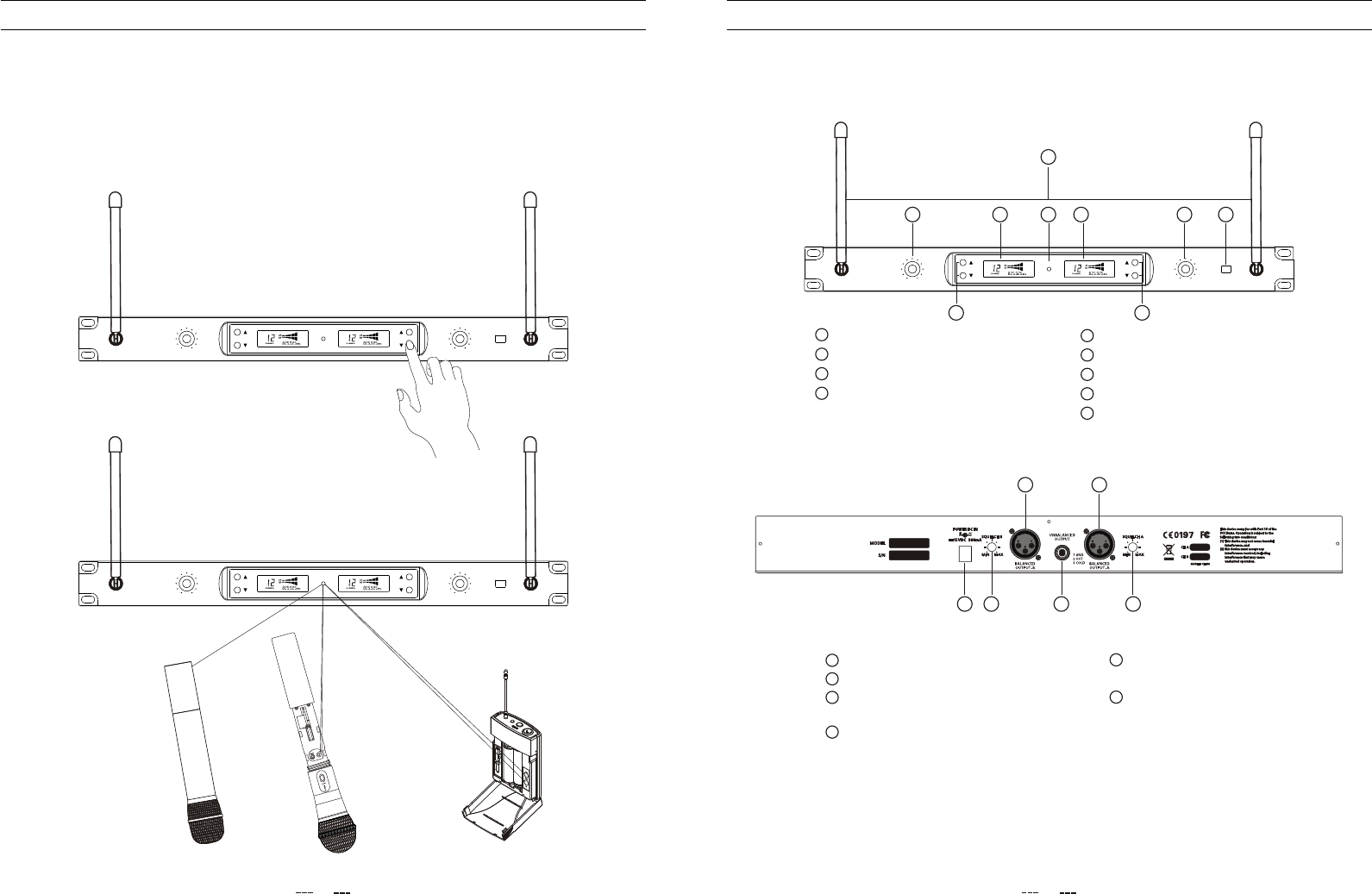
55
66
77
88
99
CHB LCD Screen
CHB Operation button
CHB adjust the volume knod
Power button/Lock
Antenna port
11
22
33
44
CHA adjust the volume knod
CHA Operation button
CHA LCD Screen
Infrarde(IR)
UP
DOWN / PAIR
IR
CH A CH B
PLL UHF DUAL RECEIVER
UP
DOWN / PAIR
ANT.A VOLUME.A VOLUME.B POWER ANT.B
11
22
334455
66
7788
99
FRONT PANEL
Receiver
11
CHB audio XLR
balanced output
22
33
Adapter jack
44 Mix audio frequency
Squel CHB
CHA audio XLR
balanced output
55
Squel CHA
66
1122
33
44
55
66
4
CONTROL ELEMENTS
Back Panel
OPERATING INSTRUCTION
Position the transmitter about 15~30cm from the front of the receiver with the transmitter s IR
window facing the IR transmitter on the front panel of the receiver.
Press and hold the receiver UP/DOWN button to set the transmitter to t he s ame c hannel a s t he
re ceiver vi a in frared tr ansmission.
When the transmission is complete, the receiver will receive RF signal and tone key from the transmitter.
The RF indicator of the screen will light on the front panel of the receiver.
,
UP
DOWN / PAIR
IR
CH A CH B
PLL UHF DUAL RECEIVER
UP
DOWN / PAIR
ANT.A VOLUME.A VOLUME.B POWER ANT.B
UP
DOWN / PAIR
IR
CH A CH B
PLL UHF DUAL RECEIVER
UP
DOWN / PAIR
ANT.A VOLUME.A VOLUME.B POWER ANT.B
11
5
CONTROL ELEMENTS
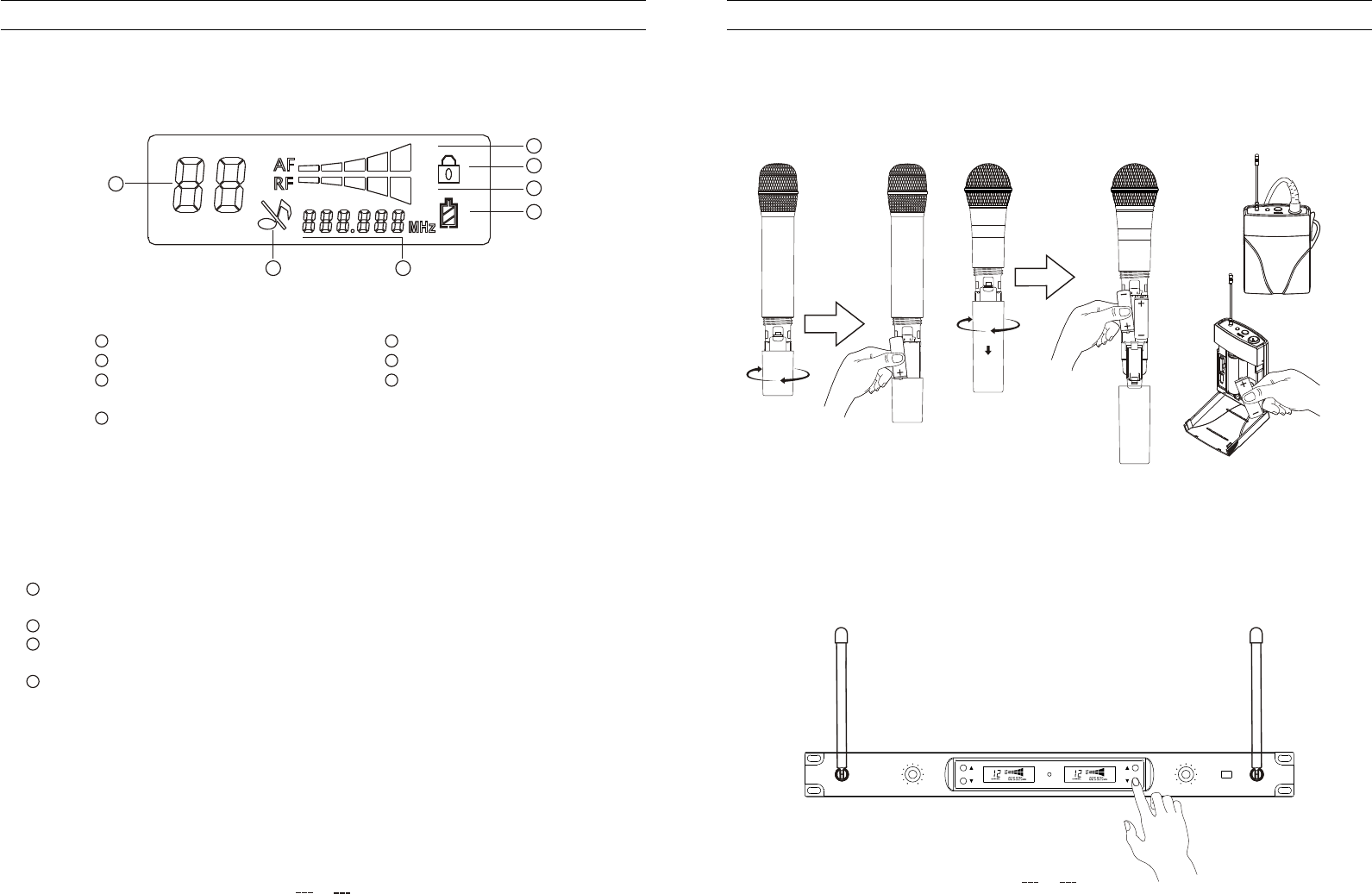
Receiver screen
Receiver power on
11
11
22
33
44
Mic power display, power
flashing the power Failure
55
66
Frequency display
RFpower indication
AFpower indication Mic Mute indication
22
33
4455
66
Frequency code
10
OPERATING INSTRUCTION
With the transmitter powered off, install two fresh AA batteries into the MIC .
Leave the battery compartment open.
Turn on the power to the transmitter by pressing and holding Power swith; the indicator LED will
light green.
Press the UP/DOWN button on the front of the receiver to choose an available
channel.
The channel number will increase by two digit,from 00-99.Once the last channel has been
reached, the count will cycle back to 00.
Press and hold the UP/DOWN button for 2 seconds to send the channel information to the
transmitter via infrared transmission.
Press and hold the UP button the display channel will be fast forward.
UP
DOWN / PAIR
IR
CH A CH B
PLL UHF DUAL RECEIVER
UP
DOWN / PAIR
ANT.A VOLUME.A VOLUME.B POWER ANT.B
Press and hold the DOWN button the display channel will be fast backward.
77
77 Button lock indication
11
33
44
Press the receiver power button continually.Receiver power on, after 2 secondsdisplay frequency
and r eady.
Receiver p ower o n,press a nd r elease t he p ower b utton t o l ock/unlock t he U P/DOWN b utton.
Press the receiver power button again continually,after 2 seconds have no frequency code display,
then loosen your hand,receiver power off.
If long time does not use the receiver,pls pull out the power adapter from the power jack.
22
12
3
12
3
SQUELCH B
MIN MAX
SQUELCH A
MIN MAX CH B
CH A
S/N
MODEL
11
2233
6
CONTROL ELEMENTS
66
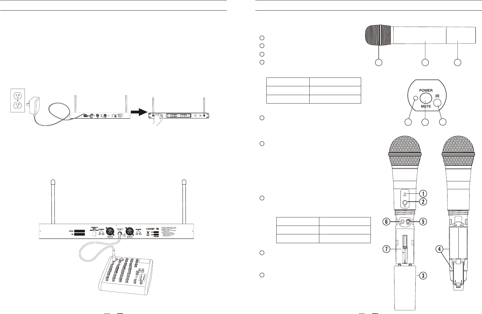
Power/Mute Switch
55
IR Receiving Section
This window is used to capture the infrared signal
sent from the receiver during the IR UP/DOWN to
channelize the transmitter.
44Status Indicator
This LED displays the operation mode:
Tail tube
33
PLASTIC HAND MIC
Grille Holder
11
22 Tube
GREEN
RED
Flashing RED
Normal Operation
Mute
Low Battery
55
44
66
METAL HANG MIC
GREEN
RED
Flashing RED
Normal Operation
Mute
Low Battery
Status indicator
11
This LED displays the operation mode:
Power/Mute Switch
22
Battery Cover
33
Unscrew the battery cover and slide down to open
the MIC battery compartment
OPERATING INSTRUCTION
In order for your wireless system to work correctly,both the receiver and transmitter must
be set to the same channel.
With your amplifier or mixer off and volume control all the way down:connect the receiver
output jack to the mic or line level input of a mixer or amplifier using the balanced XLR output or
unbalanced 1/4" line level output.Turn the Level knob on the receiver completely counterclockwise,
then turn its power on.
Follow the basic procedure for setting up and using your receiver wrieless system:
Physically place the receiver where it will be used,and extend the antennas vertically. With
the Power switch on and receiver power off,connect the included power adapter.Turn the receiver
on momentarily to confirm that the unit is receiving power. You will see the LCD display light up.
Then turn receiver power off.
9
UP
DOWN / PAIR
IR
CH A CH B
PLL UHF DUAL RECEIVER
UP
DOWN / PAIR
U-299R
ANT.A VOLUME.A VOLUME.B POWER ANT.B
Press and hold to turn the unit on or off. Press and
release to mute or unmute the transmitter.
Press and hold to turn the unit on or off. Press and
release to mute or unmute the transmitter.
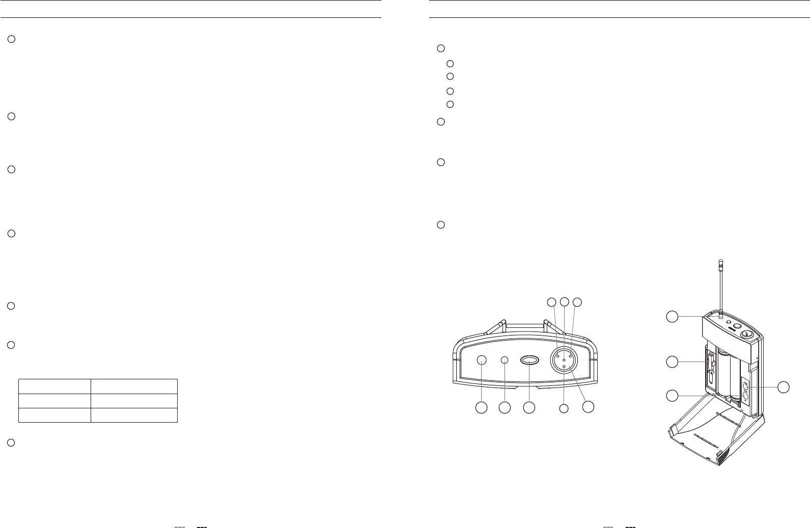
Power/Mute Switch
33
BELTPACK MIC
Antenna
11
22 Status Indicator
This permanently attached transmitter antenna should be fully extended during normal
operation.
This LED displays the operation mode:
GREEN
RED
Flashing RED
Normal Operation
Mute
Low Battery
CONTROL ELEMENTS
7
Battery Holder
44
Open the battery holder by pressing the tab and lifting the cover.insert two standard AA(LR6)
batteries here,being sure to observe the plus and minus polarity markings shown.Although
rechargeable Ni-Cad batteries can be used,they do not supply adequate current for more
than four hours.WARNING:Do not insert the batteries backwards;doing so can cause severe
damage to the MIC and will void your warranty.
Input GAIN Control
55
This control adjusts the transmitter input sensitivity.For optimal performance, using the included
screwdriver,
IR Lens
66
This w indow i s u sed t o c apture t he i nfrared s ignal s ent f rom t he d u ring th e IR U P/DOWN
t o c hannelize t he t ransmitter.The b attery c over m ust b e o pen a nd t he I R L ens f acing t owards t he
receiver to load the selected channel.
receiver
Plastic Screwdriver
77
Designed for use in adjusting the MIC input GAIN control(See #5 Input GAIN Control HH).
Set the input GAIN control to where you can see the RF display of receiver
screen become to fulllight, the n turn do wn u ntil the RF displ ay n ot full light (les sth anfive).
Input GAIN Control
This control adjusts the transmitter input sensitivity to work with microphone and instruments
inputs.For optimal performance,using the included screwdriver,
66
Driver
Designed for use in adjusting the MIC input GAIN control.
77
IR Receiving Section
This window is used to capture the infrared signal sent from the receiver during the IR UP/DOWN
to channelize the transmitter.
55
44MINI 4P CONNECTOR
CONTROL ELEMENTS
8
Pin 1, GND
Pin 4, for Dynamic or condenser microphone
Pin 2, Phantom power supply for Condenser microphone
Pin 3, for Guitar, bass and keyboards
AA
BB
CC
DD
BB
CC
AADD
44
1133
22
77
66
55
11
Set the input GAIN controlt o
where you can see the RF display of U-299R screen become to full light , th en tu rn dow n
until the T he reforedisplay not full light(less than five).
Press and hold to turn the unit on or off. Press and release to mute or unmute the transmitter.
receiver