SEIKAKU TECHNICAL GROUP UB-8H Wireless Microphone User Manual
SEIKAKU TECHNICAL GROUP LIMITED Wireless Microphone
User Manual
RR
UB-81R/81DV
UB-8H/8P SERIES
SEIKAKU TECHNICAL GROUP LIMITED
No.1, Lane 17, Sec. 2, Han Shi West Road, Taichung, 401 TAIWAN
Tel:886-4-22313737 Fax:886-4-22346757
http://www.show-pa.com e-mail: sekaku@sekaku.com
All rights reserved to SEIKAKU. All features and content might be changed
without prior notice. Any photocopy, translation, or reproduction of part of this
manual without written permission is forbidden. Copyright 2007 SEIKAKU GROUP
cc
NF02702-1.3
IMPORTANT!
Please read this manual carefully before operating
this unit for the first time.
All rights reserved to SHOW. All features and content might be changed
without prior notice. Any photocopy, translation, or reproduction of part of
this manual without written permission is forbidden.
MODEL
Oscillation mode
Carrier frequency band
Frequency response
Frequency stability
T.H.D
Modulation mode
RF output power
Dynamic :
Tone frequncy :
Curent drain :
Max.Deviation :
Battery:
Microphone Capsule
4 band choice
Dimensions :
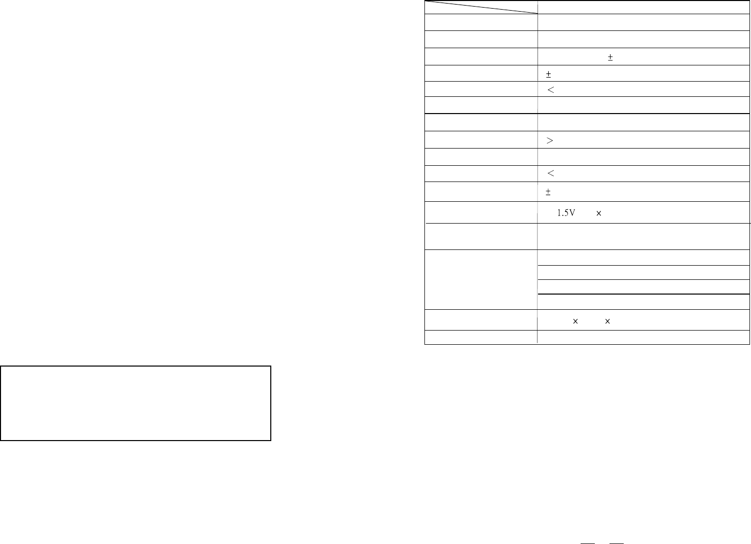
UB-8P
PLL UHF SYNTHESIZED
UHF 740~769 MHZ
50Hz~15KHz( 3dB)
0.005%
0.8%
FM(F3E)
10mw
100dB
32.768KHz
150mA
35KHZ Deviation
Condenser or Dynamic Capsule
1. Condenser
2. Dynamic
3. Electric instrument
4. Ground
65(W) 111(L) 31(H)
Weight :
0.105Kg(Approx.)
10
SPECIFICATION
"AA" type 2pcs (used for more than 6 hours)
9
SAFETY RELATED SYMBOLS
CAUTION
RISK OF ELECTRIC SHOCK
DO NOT OPEN
The symbol is used to indicate that some
hazardous live terminals are involved
within this apparatus, even under the
normal operating conditions.
The symbol is used in the service do-
cumentation to indicate that specific
component shall be only replaced by
the component specified in that docu-
mentation for safety reasons.
Protective grounding terminal.
Alternating current /voltage.
ON: Denotes the apparatus turns on.
OFF: Denotes the apparatus turns off, be-
cause of using the single pole switch, be sure
to unplug the AC power to prevent any ele-
ctric shock before you proceed your service.
WARNING: Describes precautions that
should be observed to prevent the danger
of injury or death to the user.
CAUTION: Describes precautions that
should be observed to prevent danger of the
apparatus.
WARNING
Power Supply
Ensure the source voltage matches the
voltage of the power supply before turning
ON the apparatus.
Unplug this apparatus during lightning
storms or when unused for long periods
of time.
External Connection
The external wiring connected to the out-
put hazardous live terminals requires
installation by an instructed person, or
the use of ready-made leads or cords.
Do not Remove any Cover
There are maybe some areas with high
voltages inside, to reduce the risk of electric
shock, do not remove any cover if the power
supply is connected.
The cover should be removed by the qual-
ified personnel only.
No user serviceable parts inside.
Fuse
To prevent a fire, make sure to use fuses
with specified standard (current, voltage,
type). Do not use a different fuse or short
circuit the fuse holder.
Before replacing the fuse, turn OFF the
apparatus and disconnected the power
source.
Protective Grounding
Make sure to connect the protective
grounding to prevent any electric shock
before turning ON the apparatus.
Never cut off the internal or external pro-
tective grounding wire or disconnect the
wiring of protective grounding terminal.
Operating Conditions
This apparatus shall not be exposed to
dripping or splashing and that no objects
filled with liquids, such as vases, shall be
placed on this apparatus.
To reduce the risk of fire or electric shock,
do not expose this apparatus to rain or
moisture.
Do not use this apparatus near water.
Install in accordance with the manufacturer's
Hazardous live terminal .
Disposing of this product should
not be placed in municipal waste
and should be separate collection.
MODEL
Oscillation mode
Carrier frequency band
Frequency response
Frequency stability
T.H.D
Modulation mode
RF output power
Dynamic
Tone frequency
Current drain
Max. Deviation
Battery
Microphone Capsule
Dimensions
Weight
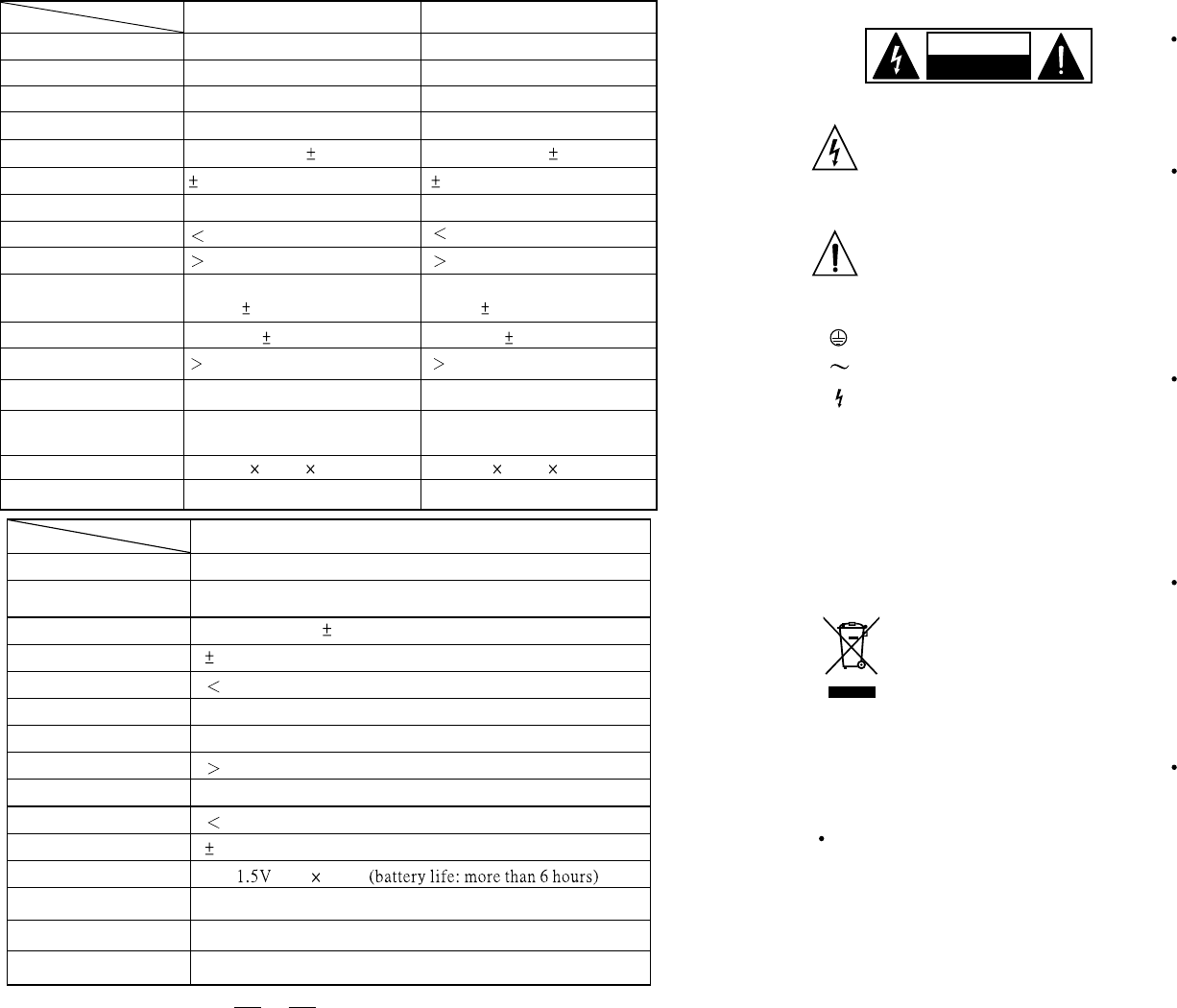
UB-8H
PLL UHF SYNTHESIZED
UHF 740~769 MHZ
50Hz~15KHz( 3dB)
0.005%
FM (F3E)
10mw
100dB
32.768KHz
150mA
35KHZ Deviation
"AA" type 2pcs
Dynamic Capsule
220mm
0.16Kg(Approx.)
0.8%
SPECIFICATION
MODEL
Channel
Receiver type
Receiver type
Frequency band
Frequency response
Frequency stability
Modulation mode
T.H.D
Dynamic
Audio Output
Balance output
S/N Ratio
RF sensitivity
Power supply
UB-81R
Single-Channel
Non-Diversity
PLL UHF SYNTHESIZED
UHF 740~769MHz
0.005%
FM(F3E)
1%
100dB
unbalanced 6.3mm phone jack
280mv 15KHz deviation
280mV at 15KHz deviation
90dB
-100dbm/30db sinad
DC 12V/500mA(AC 120V
/230V 50/60Hz Adaptor)
50Hz~50KHz( 3dB)
SPECIFICATION
UB-81DV
Single-Channel
Diversity
PLL UHF SYNTHESIZED
UHF 740~769MHz
50Hz~50KHz( 3dB)
0.005%
FM(F3E)
1%
100dB
Dimensions
130(W) 44(H) 201(L)
Weight
0.350Kg(Approx.) 0.365Kg(Approx.)
280mV at 15KHz deviation
90dB
-100dbm/30db sinad
130(W) 44(H) 201(L)
unbalanced 6.3mm phone jack
280mv 15KHz deviation
DC 12V/500mA(AC 120V
/230V 50/60Hz Adaptor)
5. TECHNICAL SPECIFICATIONS

IMPORTANT SAFETY INSTRUCTIONS
Read these instructions.
Keep these instructions.
Heed all warnings.
Only use attachments/accessories spec-
ified by the manufacturer.
Power Cord and Plug
Do not defeat the safety purpose of the
polarized or grounding type plug.
A polarized plug has two blades with
one wider than the other. A grounding
type plug has two blades and a third
grounding prong. The wide blade or the
third prong are provided for your safety.
If the provided plug does not fit into your
outlet, consult an electrician for replace-
ment of the obsolete outlet.
Protect the power cord from being walk-
ed on or pinched particularly at plugs,
convenience receptacles, and the point
where they exit from the apparatus.
Cleaning
When the apparatus needs a cleaning, you
can blow off dust from the apparatus with
a blower or clean with rag etc.
Don't use solvents such as benzol, alcohol,
or other fluids with very strong volatility and
flammability for cleaning the apparatus body.
Clean only with dry cloth.
Servicing
Refer all servicing to qualified personnel. To
reduce the risk of electric shock, do n ot perform
any servicing other than that contained in the
operating instructions unless you are qualified
to do so .
Servicing is required when the apparatus has
been damaged in any way ,such as power
supply cord or plug is damaged , liquid has
been spilled or objects have fallen into the
apparatus, the apparatus has been exposed
to rain or moisture, does not operate normally,
or has been dropped.
Follow all instructions.
instructions. Do not install near any heat
sources such as radiators, heat registers,
stoves, or other apparatus (including am-
plifiers) that produce heat. Do not block
any ventilation openings.
No naked flame sources, such as lighted
candles, should be placed on the apparatus.
8
4.3 OPERATING FREQUENCY MATCHES BETWEEN THE RECEIVER AND
THE TRANSMITTER
To make the operating frequency matched between the transmitter and the receiver,
adjust the transmitter and receiver manually with the adjusting bar for the same
frequency. Please refer to the following table for selecting frequency.
Caution: a: If several apparatus are used at the same time, the same frequency can not
be used for them.
See the table F6
CH0~CHF
0
1
2
3
4
5
6
7
8
9
A
B
C
D
E
F
b: Ten channels can be used simultaneously at most. They are respectively
CH0, CH1, CH3, CH4, CH6, CH7, CH8, CH9, CHE, CHF. The rest 6 channels
are available for customer's choice.
FREQUENCY
See the table F6
See the table F6
See the table F6
See the table F6
See the table F6
See the table F6
See the table F6
See the table F6
See the table F6
See the table F6
See the table F6
See the table F6
See the table F6
See the table F6
See the table F6
This device complies with Part 15 of the
FCC Rules. Operation is subject to the
following two conditions: (1) this device may
not cause harmful interference, and (2) this
device must accept any interference received,
including interference that may cause undesired
operation.
WARNING: changes or modifications not expressly
approved by the party responsible for compliance could
void the user's authority to operate the equipment.
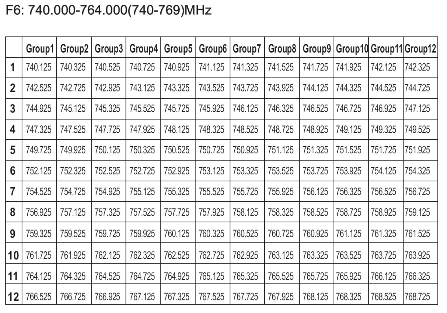

TABLE OF CONTENTS
1. INTRODUCTION......................................................................................1
2. FEATURES..............................................................................................3
3. CONTROL ELEMENTS...........................................................................3
4. OPERATION............................................................................................7
5. TECHNICAL SPECIFICATIONS..............................................................9
7
4. OPERATION
4.1 FOR the UB-81R/81DV, PLL UHF DIVERSITY RECEIVER
- MANUALLY SELECTING FREQUENCY
With an adjusting bar, adjust the band selector to select the right frequency which matches
the frequency of transmitter.
- OUTPUT VOLUME CONTROL
It is used to control the output volume. Turn the knob clockwise and the output volume
increases. Turn the knob counter- clockwise and the output volume decreases.
The job of a squelch circuit is to reduce audible noise. It eliminates noise during
pauses in the audio signal by muting the receiver every time and the audio level
drops below a defined threshold. The squelch control on the receiver sets this
threshold. Use the squelch control with care! If the squelch threshold is too
high, the squelch will not only cut out noise but mute quiet audio signals as
well because the squelch responds to the detected voltage and cannot
distinguish between wanted signal and noise. Besides that, a too high squelch
threshold also decreases the usable range. The squelch range is 95.0dB~65.
0dB. Use an adjusting bar to adjust the squelch selector for a right squelch
threshold.
- SQUELCH CONTROL
4.2 FOR the UB-8H/8P SERIES TRANSMITTER
4.2.1 FREQUENCY SELECT
In practice, to effectively avoid the interference from any lighting equipment, Com-
puters, fax machines, etc nearby, It is usually advised to switch to another
frequency to get best performance.
The frequency range of this system is UHF, 740MHz ~ 769MHz, and it is divided into
16 frequency bands according to the country's EMC regulations; Each frequency band
can be manually adjusted with an adjusting bar. If you want to switch a frequency, you
have to turn off the unit, adjust frequency and then turn it on again.
4.2.2 BATTERY REPLACING AND CHARGING
Please be advised to use only one pair of AA 1.5V batteries for power supply.
Caution: Danger of explosion if battery is incorrectly replaced. Replace the batteries
only with the same or equivalent type.
1
1. INTRODUCTION
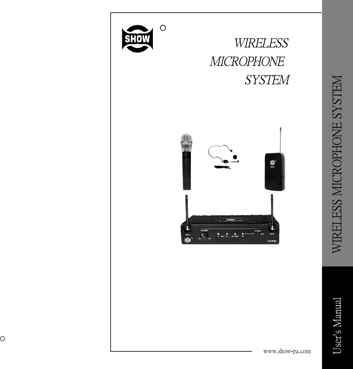
Thanks for purchasing the SHOW wireless microphone system. The UB-8H/8P/81R/81DV
Series is the delicately designed UHF, PLL synthesized system, with antenna built inside
the receiver for smart switching diversity control, the higher level RF signals maybe fed
into the system for greater reliability and coverage, therefore, the risks of breakdown
and interference are to be effectively reduced.
You can manually adjust the channel of the transmitter to match that of the receiver if
you know about the operating frequency of it.
Generally, the UB-8H/8P/81R/81DV series consists of
-UB-81DV, PLL UHF Diversity Receiver
-UB-8H, Handheld transmitter
-UB-8P series, Body Pack transmitter
UB-81DV, PLL UHF DIVERSITY RECEIVER
-UB-81R, PLL UHF Diversity Receiver
UB-81R, PLL UHF DIVERSITY RECEIVER
UB-8H, HANDHELD TRANSMITTER
6
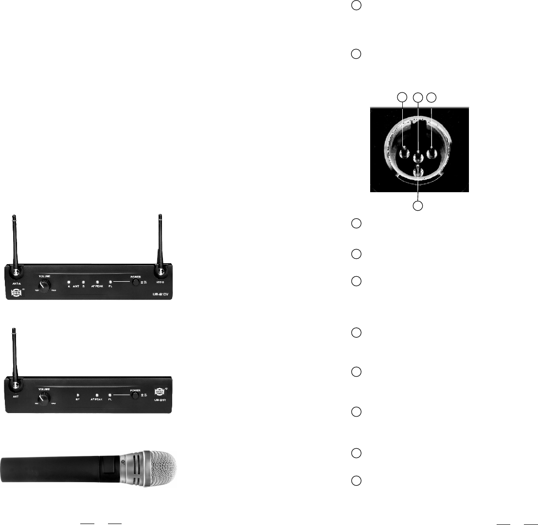
POWER SWITCH
Set the power switch in the position ON, then the microphone is turned on and
the flashes once. Set the power switch in the position OFF, then the microphone
is turned off and the BATT LED lights off slowly.
1 1
2 2
MINI 4P CONNECTOR
This connector is used to connect the unit with the clip microphones, for example, HM-38
or HM-58 condenser microphones.
3 3
1 1 4 4
2 2
Pin 1, GND
Pin 4, for Dynamic or condenser microphone
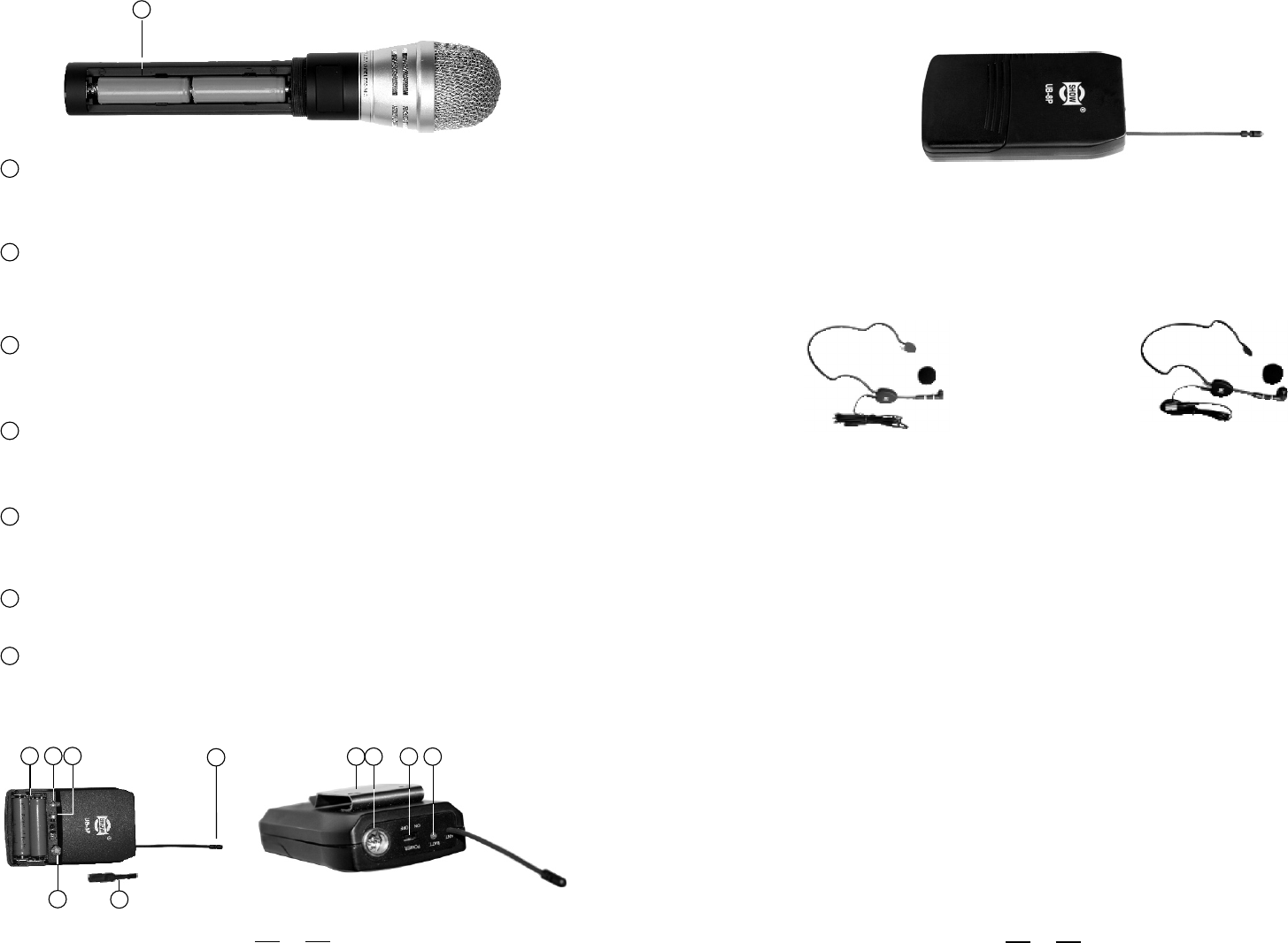
ANTENNA
It is the flexible antenna. To get effective transmission, never cover the antenna with
hand, clothes, etc during the operation, and always position the transmitter nearby the
receiver.
5 5
BATTERY COMPARTMENT
This unit may be powered from one pair dry or rechargeable batteries, UM3 size AA 1.5V.
3 3
BELT CLIP
It is the detachable belt clip for easy carry during the live applications.
4 4
Pin 2, Phantom power supply for Condenser microphone
Pin 3, for Guitar, bass and keyboards
GT SWITCH
It is used to adjust the input signal level of electrical guitar. When an electrical guitar is being
used it is ineffective to adjust MT switch.
6 6
MT SWITCH
It is used to adjust the input signal level of microphone. When an microphone is being used
it is ineffective to adjust GT switch.
7 7
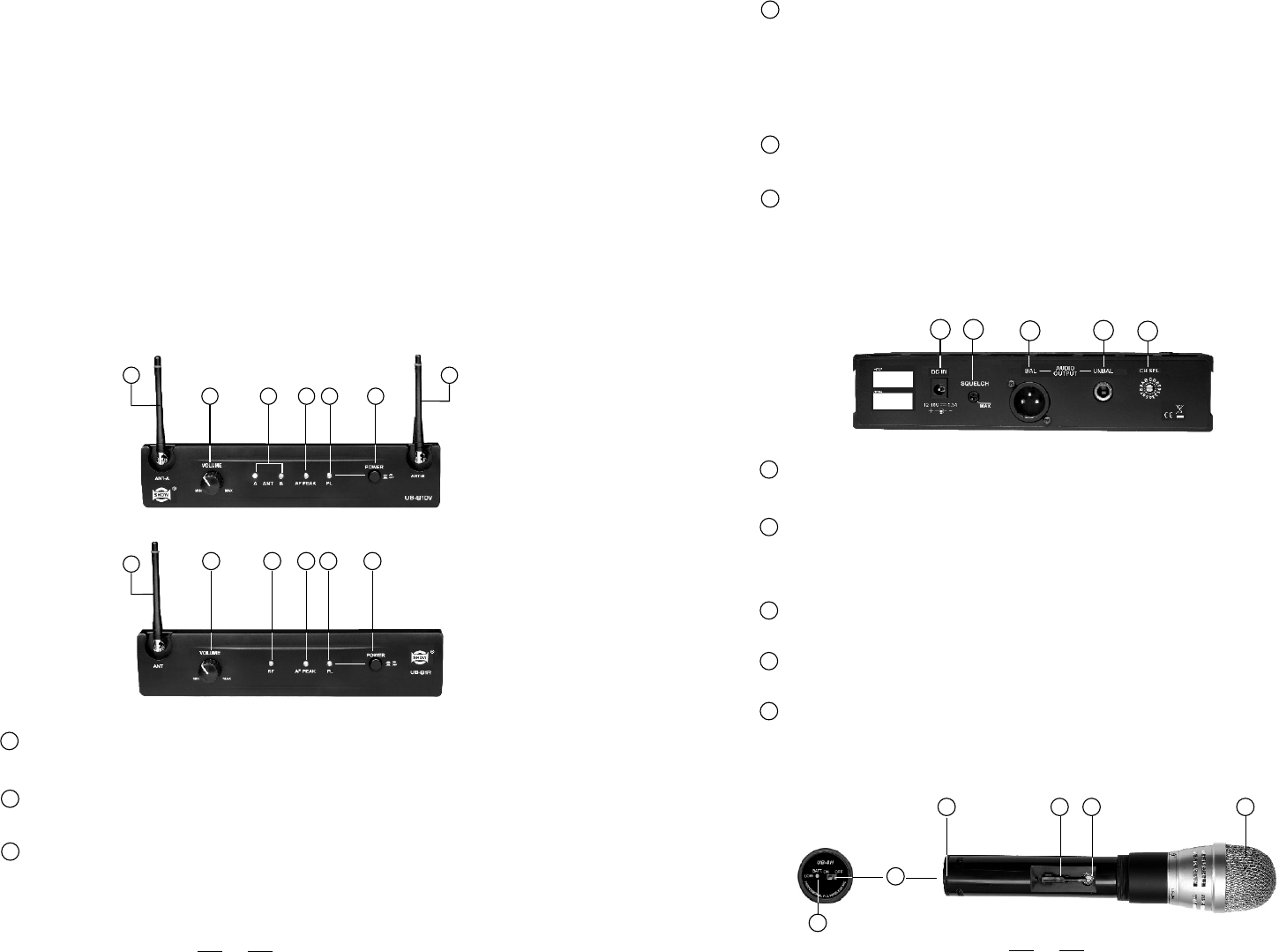
BAND SELECTOR
With the adjusting bar, the band selector can be used to switch to an expected frequency
before switching the frequencies, turn off the transmitter first and then turn on it.
8 8
ADJUSTING BAR
It is used to adjust BAND SELECTOR, MT SWITCH and GT SWITCH.
9 9
POWER LED
When the unit is turned on this LED flashes once. When the unit is turned off this LED lights
off slowly. When the batteries are short of power, this LED flashes. When the batteries can
not be used this LED lights up.
10 10
52
UB-8P SERIES, BODY PACK TRANSMITTER
For the UB-8P series, there are several types of clip microphone are included in this
product range, please make sure that the proper microphone has been selected for
your typical sound reinforcement system before installation.
7 7
is turned off and the BATT LED lights off slowly.
With an adjusting bar, the band selector can be used to switch to an expected frequency.
Before switching frequencies, turn off the microphone first and then turn on it.
The antenna is integrated into the transmitter body for transmitting signals.
BAND SELECTOR
4 4
ANTENNA
6 6
3 3 5 5 2 2
3.3 UB-8P SERIES, BODY PACK TRANSMITTER
Extremely rugged spring steel mesh grill to protect the capsule underneath in tough
stage or live performance.
MASSIVE FRONT GRILL
1 1
Set the power switch in the position ON, then the microphone is turned on and the
BATT LED flashes once. Set the power switch in the position OFF, then the microphone
POWER SWITCH
2 2
The unit may be powered from a dry or rechargeable battery.
BATTERY COMPARTMENT
7 7
This adjusting bar is placed in the microphone. It is used to adjust squelch control and band
selector for switching frequencies.
ADJUSTING BAR
5 5
1 1 4 4
6 6 7 7
8899
10 10
2. FEATURES
-UB-81R/81DV, PLL UHF DIVERSITY RECEIVER
-LED indication for RF, AF PEAK and POWER;
-Squelch control;
Last but not the least, the operating frequency of this system may be varied from 798MHz
to 827MHz, please refer to your national EMC regulations to pick out the authorized
frequency band (0 ~ F) for your end application.
-Switching diversity control to receive the RF signal;
-Output volume control;
HM-38, Condenser microphone
Preset impedance: 600ohm;
Freq. response: 80-12KHz;
Sensitivity: -68dB+/-3dB at 1KHz;
Directional: Uni-directional;
Weight: 52g (0.12Ib)
HM-58, Condenser microphone
Preset impedance: 700ohm;
Freq. response: 200-8KHz;
Sensitivity: -65dB at 1KHz;
Directional: Uni-directional;
Weight: 54g (0.12Ib)
When the unit is turned on, this LED flashes once. When the unit is turned off, this
LED lights off slowly. When the batteries are short of power, this LED lights up.
POWER LED
3 3
4
-Soft touch painting for comfortable use;
-COMMON FEATURES,
-PLL synthesized design;
-Consistent operating frequencies to comply with the EMC regulations;
-16 channel frequency presets;
-Manufactured under ISO9000:2000, ISO/TS16949:2002 quality management system;
3. CONTROL ELEMENTS
3.1 UB-81R/81DV, PLL UHF DIVERSITY RECEIVER
POWER SWITCH
It switches on/off UB-81R/81DV main power.
1 1
THE FRONT PANEL
-Channel frequency adjusted manually
3
RF LED
This LED lights up when antenna receives signals.
Note: UB-81DV has two antennas. LED A lights up when antenna A receives more
signals than antenna B. LED B lights up when antenna B receives more signals than
antenna A.
4 4
POWER LED
This LED lights up when the receiver is powered on and vice versa.
AF PEAK LED
This LED lights up when the signal reaches PEAK and sound is distorted.
2 2
3 3
It is used to adjust the volume of receiver.
VOLUME CONTROL
5 5
THE REAR PANEL
DC JACK
This DC jack is used to connect DC 12~18V for the receiver.
XLR AUDIO OUTPUT
This is a professional balanced XLR output connector.
AUDIO OUTPUT JACK
This is a professional unbalanced output jack.
1 1
3 3
4 4
3.2 UB-8H, HANDHELD TRANSMITTER
4 4
2 2
SQUELCH CONTROL
It is used to adjust the squelch level by using an adjusting bar which is placed in the
microphone. The adjustable squelch range is 95.0~65.0dB.
FREQUENCY BAND SELECTOR
Using a select bar, you can select the right frequency band you want.
5 5
2 2
3 3
5 5
6 6
The antenna receives the signals from transmitter. .
Note: 81DV has two antennas and 81R has only one antenna.
ANTENNA
6 6
2 2
3 3 4 4
5 5 1 1
6 6 6 6
5 5 4 4 3 3 2 2 1 1
-UB-8H/8P TRANSMITTER,
6 6
1 1 2 2 3 3 4 4 5 5
1 1