SEIKAKU TECHNICAL GROUP UPUL-MODAU-HM Wireless Microphone User Manual UL 82DR 8H 8P SHOW FCC
SEIKAKU TECHNICAL GROUP LIMITED Wireless Microphone UL 82DR 8H 8P SHOW FCC
Contents
- 1. User Manual I
- 2. User Manual II
- 3. User Manual III
- 4. User Manual IV
- 5. User Manual V
User Manual IV
R
UL-82DR
UL-81H/UL-881H/UL-83H/UL-883H
UL-86H/UL-886H/UL-87CH/UL-887CH
UL-8P/UL-88P/UL-8G/UL-88G SERIES
No.1, Lane 17, Sec. 2, Han Shi West Road, Taichung, 401 TAIWAN
Tel:886-4-22313737 Fax:886-4-22346757
http://www.show-pa.com e-mail: sekaku@sekaku.com
All rights reserved to SEIKAKU. All features and content might be changed
without prior notice. Any photocopy, translation, or reproduction of part of this
manual without written permission is forbidden. Copyright 2006 SEIKAKU GROUP
c
NF02603-1.0
IMPORTANT!
Please read this manual carefully before operating
this unit for the first time.
All rights reserved to SHOW. All features and content might be changed
without prior notice. Any photocopy, translation, or reproduction of part of
this manual without written permission is forbidden.
18
SAFETY RELATED SYMBOLS
CAUTION
RISK OF ELECTRIC SHOCK
DO NOT OPEN
The symbol is used to indicate that some
hazardous live terminals are involved
within this apparatus, even under the
normal operating conditions.
The symbol is used in the service do-
cumentation to indicate that specific
component shall be only replaced by
the component specified in that docu-
mentation for safety reasons.
Protective grounding terminal.
Alternating current /voltage.
ON: Denotes the apparatus turns on.
OFF: Denotes the apparatus turns off, be-
cause of using the single pole switch, be sure
to unplug the AC power to prevent any ele-
ctric shock before you proceed your service.
WARNING: Describes precautions that
should be observed to prevent the danger
of injury or death to the user.
CAUTION: Describes precautions that
should be observed to prevent danger of the
apparatus.
WARNING
Power Supply
Ensure the source voltage matches the
voltage of the power supply before turning
ON the apparatus.
Unplug this apparatus during lightning
storms or when unused for long periods
of time.
External Connection
The external wiring connected to the out-
put hazardous live terminals requires
installation by an instructed person, or
the use of ready-made leads or cords.
Do not Remove any Cover
There are maybe some areas with high
voltages inside, to reduce the risk of electric
shock, do not remove any cover if the power
supply is connected.
The cover should be removed by the qual-
ified personnel only.
No user serviceable parts inside.
Fuse
To prevent a fire, make sure to use fuses
with specified standard (current, voltage,
type). Do not use a different fuse or short
circuit the fuse holder.
Before replacing the fuse, turn OFF the
apparatus and disconnected the power
source.
Protective Grounding
Make sure to connect the protective
grounding to prevent any electric shock
before turning ON the apparatus.
Never cut off the internal or external pro-
tective grounding wire or disconnect the
wiring of protective grounding terminal.
Operating Conditions
This apparatus shall not be exposed to
dripping or splashing and that no objects
filled with liquids, such as vases, shall be
placed on this apparatus.
To reduce the risk of fire or electric shock,
do not expose this apparatus to rain or
moisture.
Do not use this apparatus near water.
Install in accordance with the manufacturer's
Hazardous live terminal .
Disposing of this product should
not be placed in municipal waste
and should be separate collection.
17
IMPORTANT SAFETY INSTRUCTIONS
Read these instructions.
Keep these instructions.
Heed all warnings.
Only use attachments/accessories spec-
ified by the manufacturer.
Power Cord and Plug
Do not defeat the safety purpose of the
polarized or grounding type plug.
A polarized plug has two blades with
one wider than the other. A grounding
type plug has two blades and a third
grounding prong. The wide blade or the
third prong are provided for your safety.
If the provided plug does not fit into your
outlet, consult an electrician for replace-
ment of the obsolete outlet.
Protect the power cord from being walk-
ed on or pinched particularly at plugs,
convenience receptacles, and the point
where they exit from the apparatus.
Cleaning
When the apparatus needs a cleaning, you
can blow off dust from the apparatus with
a blower or clean with rag etc.
Don't use solvents such as benzol, alcohol,
or other fluids with very strong volatility and
flammability for cleaning the apparatus body.
Clean only with dry cloth.
Servicing
Refer all servicing to qualified personnel. To
reduce the risk of electric shock, do not perform
any servicing other than that contained in the
operating instructions unless you are qualified
to do so .
Servicing is required when the apparatus has
been damaged in any way ,such as power
supply cord or plug is damaged , liquid has
been spilled or objects have fallen into the
apparatus, the apparatus has been exposed
to rain or moisture, does not operate normally,
or has been dropped.
Follow all instructions.
instructions. Do not install near any heat
sources such as radiators, heat registers,
stoves, or other apparatus (including am-
plifiers) that produce heat. Do not block
any ventilation openings.
No naked flame sources, such as lighted
candles, should be placed on the apparatus.
16
This device complies with Part 15 of the FCC Rules.
Operation is subject to the following two conditions:
(1) this device may not cause harmful interference,
and (2) this device must accept any interference received,
including interference that may cause undesired operation.
WARNING: changes or modifications not expressly
approved by the party responsible for compliance could
void the user's authority to operate the equipment.
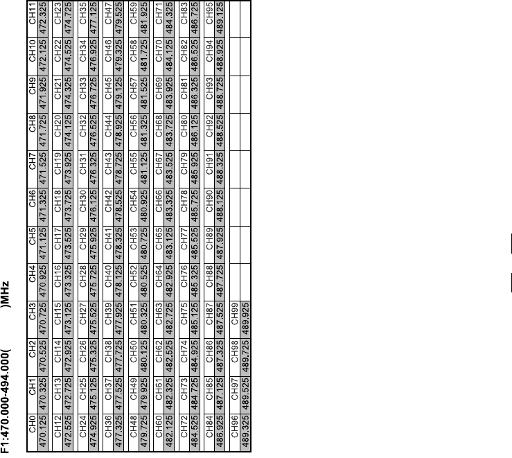
TABLE OF CONTENTS
1. .. . 1
2. ...... ......... . ........... . ....................5
3. .... . .. .... ......... .............5
4. ... .. ... ... . ... . . ....................8
5.
6.
INTRODUCTION
FEATURES
CONTROL ELEMENTS
OPERATION
TECHNICAL SPECIFICATIONS
ANNEX
. ..................................................................................
.... . ..................... ..... ...............
........ . ..... .......................... ..
... .. .. ... ...................... ..... ........ ..........
............................................................14
...................................................................................................16
15
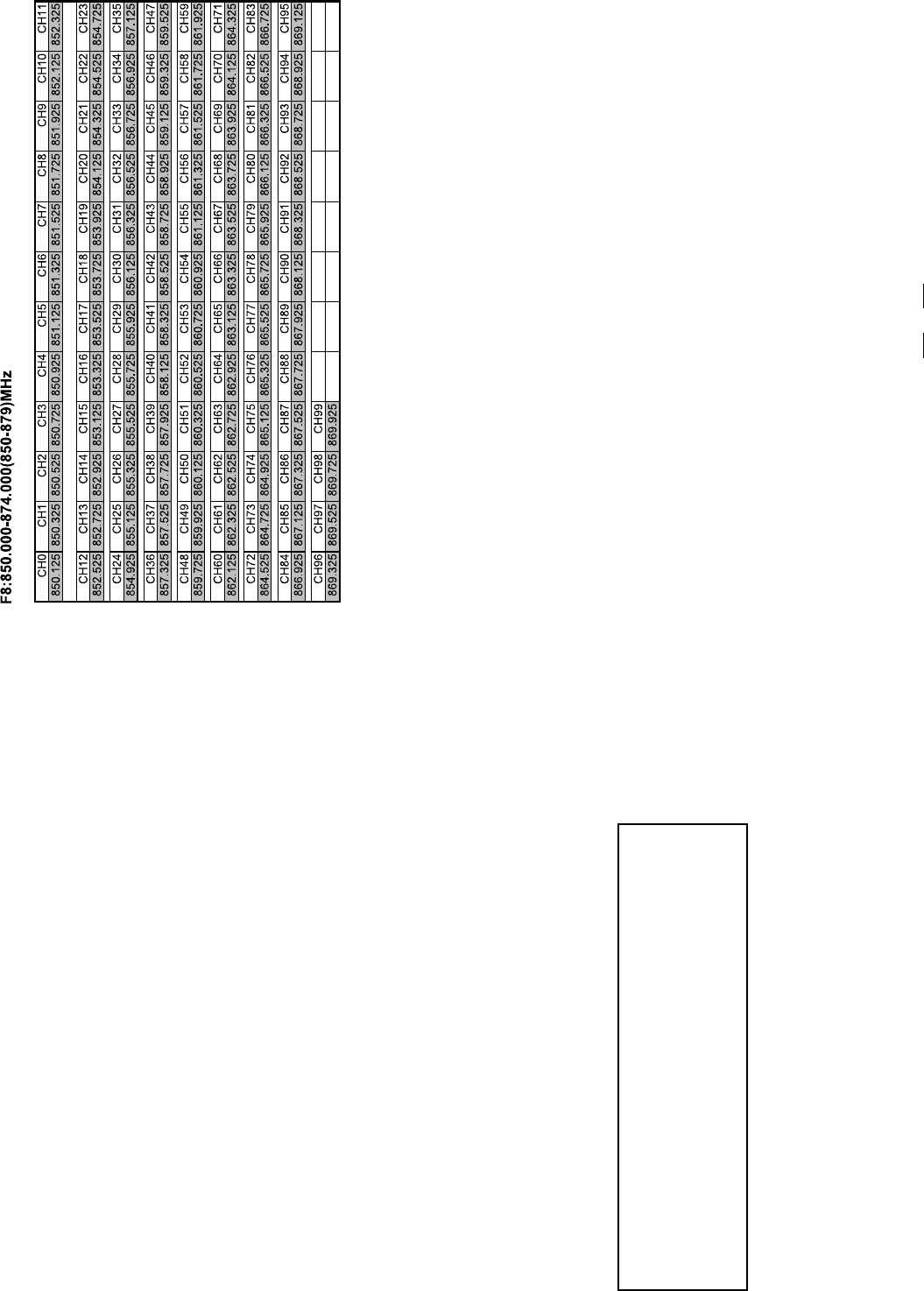
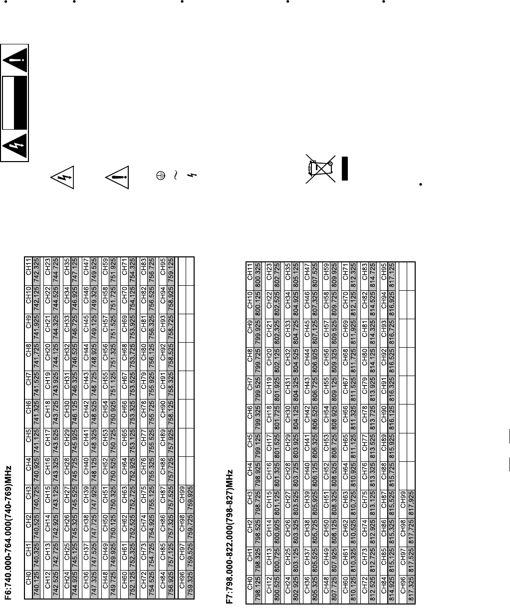
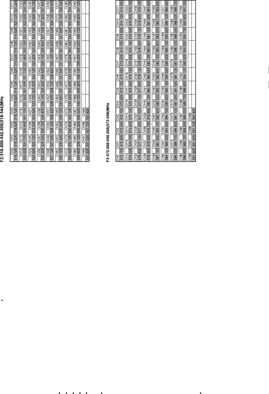
6. ANNEX
Most countries closely regulate the radio frequencies used in the transmission of
wireless information. These regulations state which devices can use which frequencies,
and help to limit the amount of RF(radio frequency)interference in all wireless
communications. To be flexible enough to operate worldwide, UL-82DR Wireless
receivers are available in a number of models, each with a unique frequency range.
Each frequency range, or band, spans up to 24MHz of the wireless broadcast
spectrum.
6.1 Frequency Band Selection
6.2 Frequency Ranges
470~496
1
1. INTRODUCTION
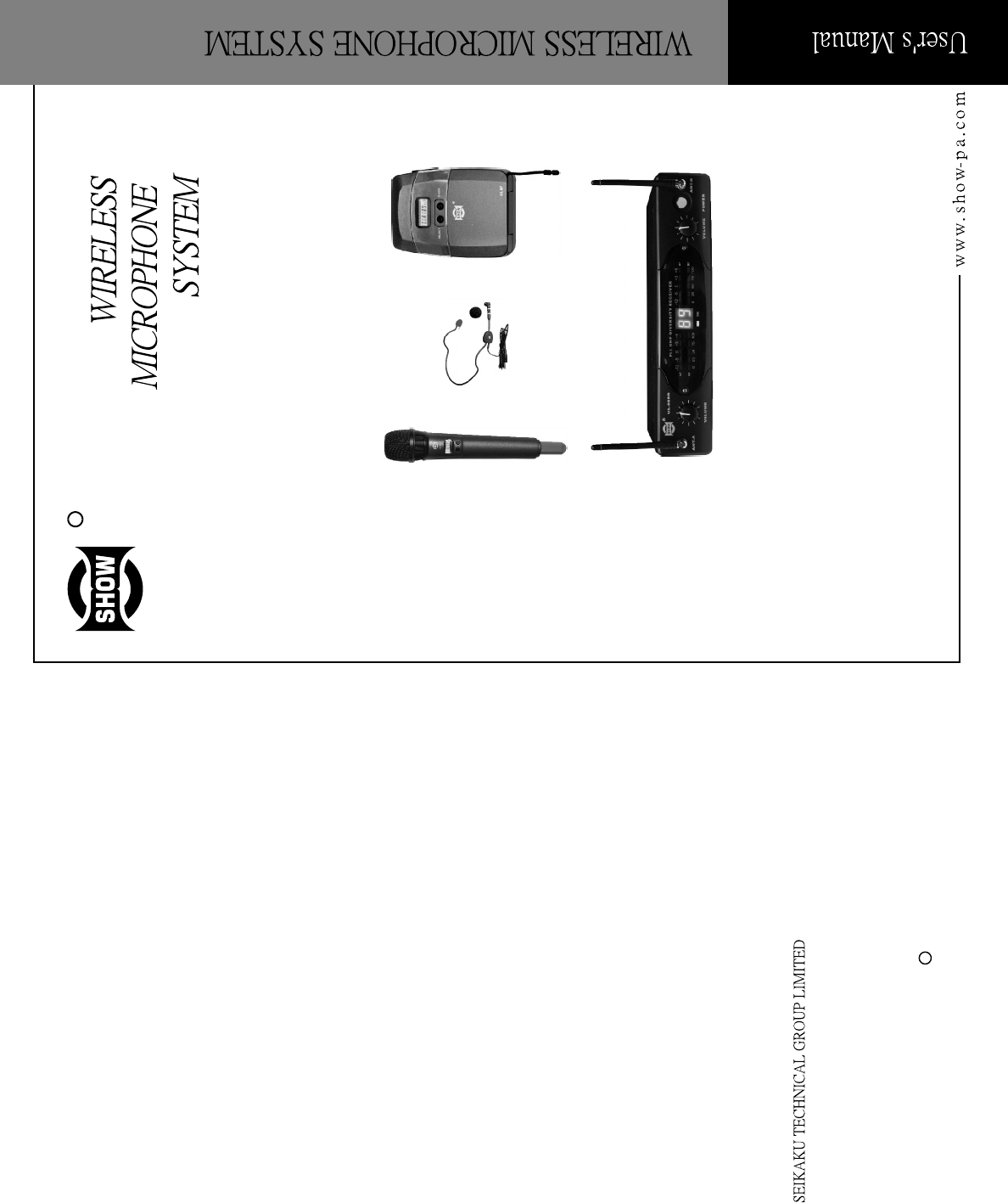
Thanks for purchasing the SHOW wireless microphone system. The UL-82DR/H/P/G
series is the delicately designed UHF, PLL synthesized system, with two antennas built
inside the receiver for smart switching diversity control, the higher level RF signals may
be fed into the system for greater reliability and coverage, therefore, the risks of breakdown
and interference are to be effectively reduced. Moreover, you can manually adjust the
channel of the transmitter to match the receiver in case you know about the operating
frequency of it.
Generally, the UL-82DR/H/P/G series consists of
-UL-82DR, PLL UHF Diversity Receiver
-UL-H series, Handheld Transmitter
-UL-P/G series, Body Pack Transmitter
UL-82DR, PLL UHF Diversity Receiver
UL-H series, Handheld transmitter
To well satisfy the different applications , there are included in
this product range, please make sure that the proper microphone has been selected
for your typical sound reinforcement system before installation.
MODEL
Oscillation mode
Carrier frequency band
Frequency response
Frequency stability
T.H.D.
Modulation mode
RF output power
Dynamic
Tone frequency
Current drain
Max. Deviation
Battery
Optional
Mic. Capsule(optional)
Dimensions
Weight
UL-81H/881H/83H/883H/86H/886H
UL-87CH/887CH/88CH/888CH
PLL UHF SYNTHESIZED
UHF 470-900 MHz
Dependent on applicable country regulations
50 Hz-15KHz ( 3dB)
0.005% (-10 ~ 50 )
FM (F3E)
5-50mW(adjustable 3 bands)
100dB
32.768KHz
100mA
35KHz
"AA" type 2
Nickel hydrogen battery +charger
Condenser or Dynamic Capsule
277 36.5mm (10.9" 1.44")
0.246Kg
UL-8P/88P/8G/88G
1KHz<0.8%
Condenser or Dynamic Capsule
0.009Kg
97mm 68mm 22mm(3.82" 2.68" 0.87")
SPECIFICATION
14
UL-H series Handheld Transmitter
Model No. Capsule
UL-81H/UP-881H Dynamic(S-100)
UL-83H/UP-883H Dynamic(S-600)
UL-86H/UP-886H Dynamic(S-500)
UL-87CH/UP-887CH Condenser(C-100)
UL-88CH/UP-888CH Condenser(C-200)
2
Type: Dynamic Mic.
Frequency response: 50Hz~16kHz( 3dB)
Impedance: 300 20% at 1kHz
Sensitivity: -71dB 3dB
Direction: Omni-directional
S-600
13
5. TECHNICAL SPECIFICATIONS
MODEL UL-82DR
Channel Dual-Channel , up to 100 frequency presets
for each frequency bands
Frequency band UHF 470-900 MHz Dependent on applicable
country regulations
Receiver Type PLL UHF SYNTHESIZED
Frequency response 50 Hz-15KHz ( 3dB)
Frequency stability 0.005% (-10 ~ 50)
T.H.D. 1KHz <0.8%
Modulation mode FM (F3E)
S/N Ratio >90dB
Dynamic >100dB
RF sensitivity -100dBm/30dB SINAD
Audio output unbalanced 6.3mm phone jack 550mV ;
20KHz deviation
balance output 1V, 20KHz deviation
Power supply DC 12V/500mA
AC (115V/120V/230V 50/60Hz Adaptor)
Dimensions 217(W)x101.5(D)x44(H)mm (8.5"x4.0"x1.7")
Weight 0.54Kg
Type: Dynamic Mic.
Frequency response: 50Hz~15kHz( 3dB)
Impedance: 270 20% at 1kHz
Sensitivity: 0.005%
Direction: Omni-directional
S-100
S-500
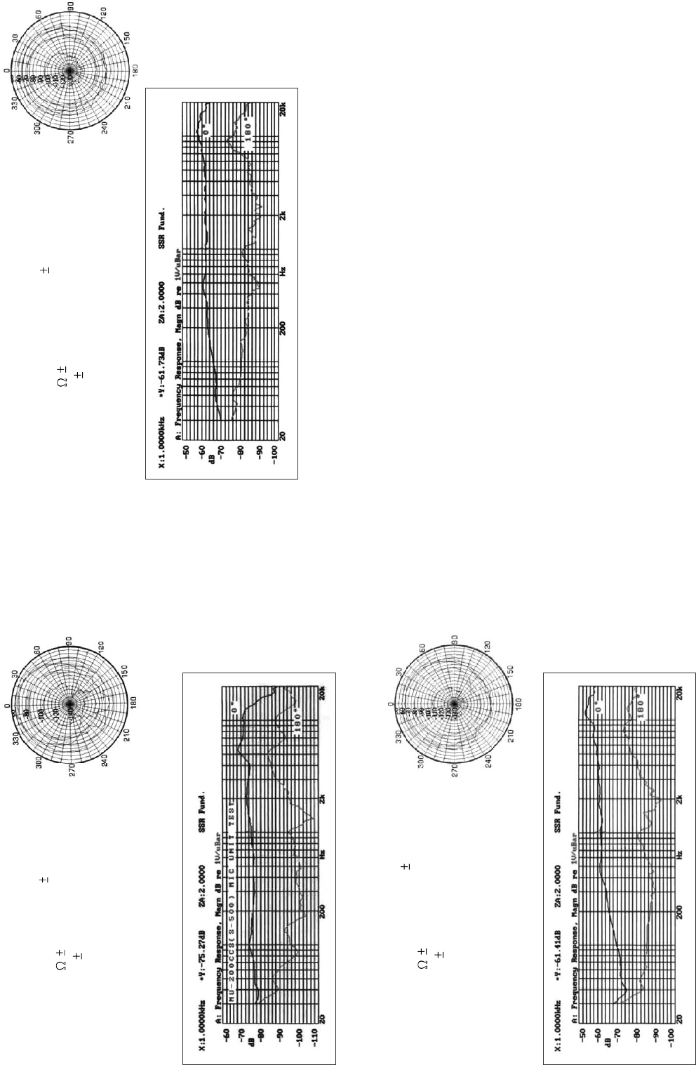
Type: Dynamic Mic.
Frequency response: 90Hz~12kHz( 3dB)
Impedance: 680 20% at 1kHz
Sensitivity: -52dB 3dB
Direction: Uni-directional
C-100
Type: Condenser Mic.
Frequency response: 50Hz~15kHz( 3dB)
Impedance: 270 20% at 1kHz
Sensitivity: -71dB 3dB
Direction: Omni-directional
C-200
Type: Condenser Mic.
Frequency response: 100Hz~15kHz( 3dB)
Impedance: 700 30% at 1kHz
Sensitivity: -44dB 3dB
Direction: Uni-directional
470MHz to 900MHz, please refer to your national EMC regulations to pick out the authorized
frequency band (F1 ~ F8, detail please see Annex hereafter) for your end application.
Last but not the least, the operating frequency of this wireless system may be varied from
UL-P/G series, Body Pack transmitter
For the UL-P/G series, there are several types of clip microphone are included in this product
range, please make sure that the proper microphone has been selected for your typical
sound reinforcement system before installation.
HM-38, Condenser microphone
Preset impedance: 600ohm;
Freq. response: 80-12KHz;
Sensitivity: -68dB+/-3dB at 1KHz;
Directional: Uni-directional;
Weight: 52g (0.12Ib)
3
4.3 Operating frequency matches between the receiver and the transmitter
12
4
Fig 7
4.2.3 Mute Mode Operation
Keep pressing the SELECT key for a few seconds, the unit will enter into the mute mode
(see the Fig 7), repeat for unmute.
Note: when the transmitter is muted, the microphone couldn't send out any AF signal, it means
no sound would be sent out from the microphone.
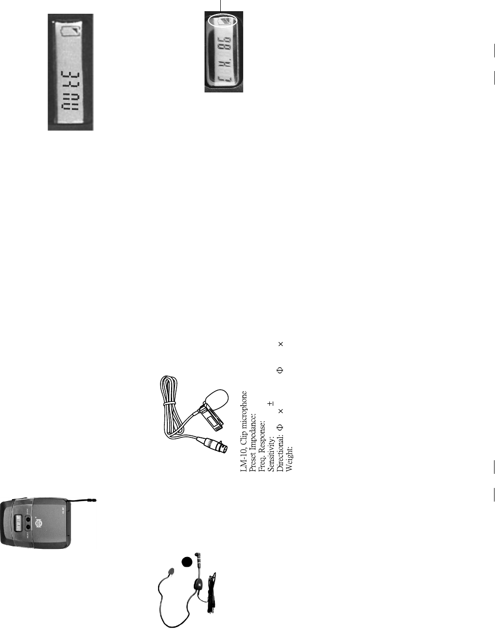
4.2.4 Battery Replacing and Charging
If you need to change the dry battery, please open the battery compartment, and then
place the new dry battery.
If you use rechargeable battery, you don't even have to remove
the battery for charging! Just use the special optional charger, which is available from
our company, connecting to the charge jack , when the transmitter is charging, the battery
logo on the LCD will be flashing. The battery is recharged within six hours.
Battery Logo flashes
Fig 8
- Adjust from the transmitter,
1) Check the preset frequency (preset channel) displayed on the receiver.
2) Switch on the transmitter.
3) Touch the CH/ON key slightly to select the parameters to be edited.
4) Use the Select key to set the proper channel.
680 ohm
50-12 kHz;
-65 dB 3 dB at 1kHz
12 180 mm( 0.47" 7.1")
22g(0.049Ib)
- RF Output Power Select
RF output power adjusting circuit is designed to reduce emission interference as much
as possible. When the receiver is much close to the transmitter, please reduce RF
output power moderately, when the distance between the receiver and the transmitter
is too long, please increase RF output power moderately. Press CH/ON key, the
transmitter is in Menu mode, Fig 4 is of RF output power select, press the SELECT key
to select the output power you need, 0: the output power is 5dB, 1: the output power
is 10dB, 2: the output power is 15dB.
Fig 4
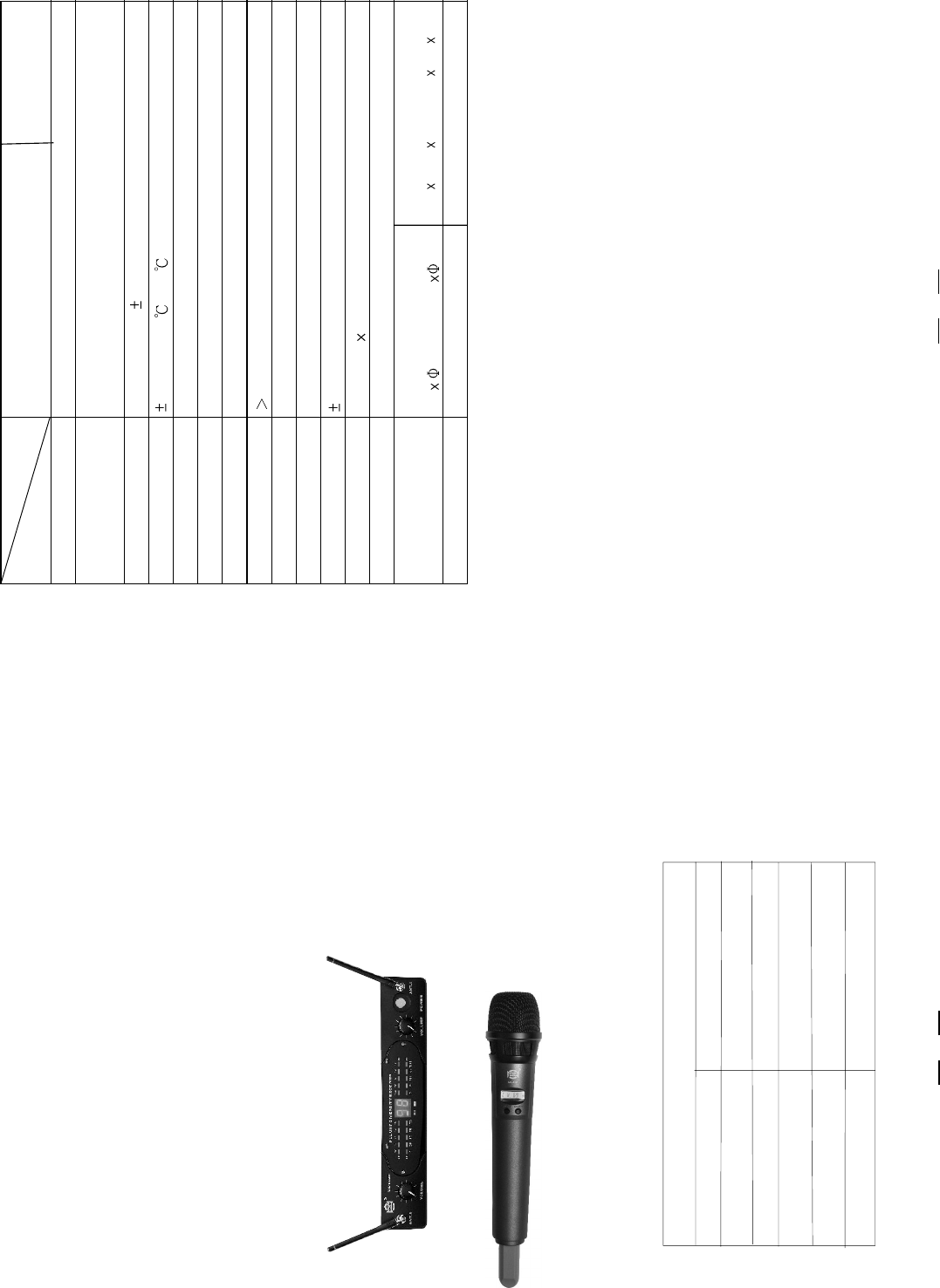
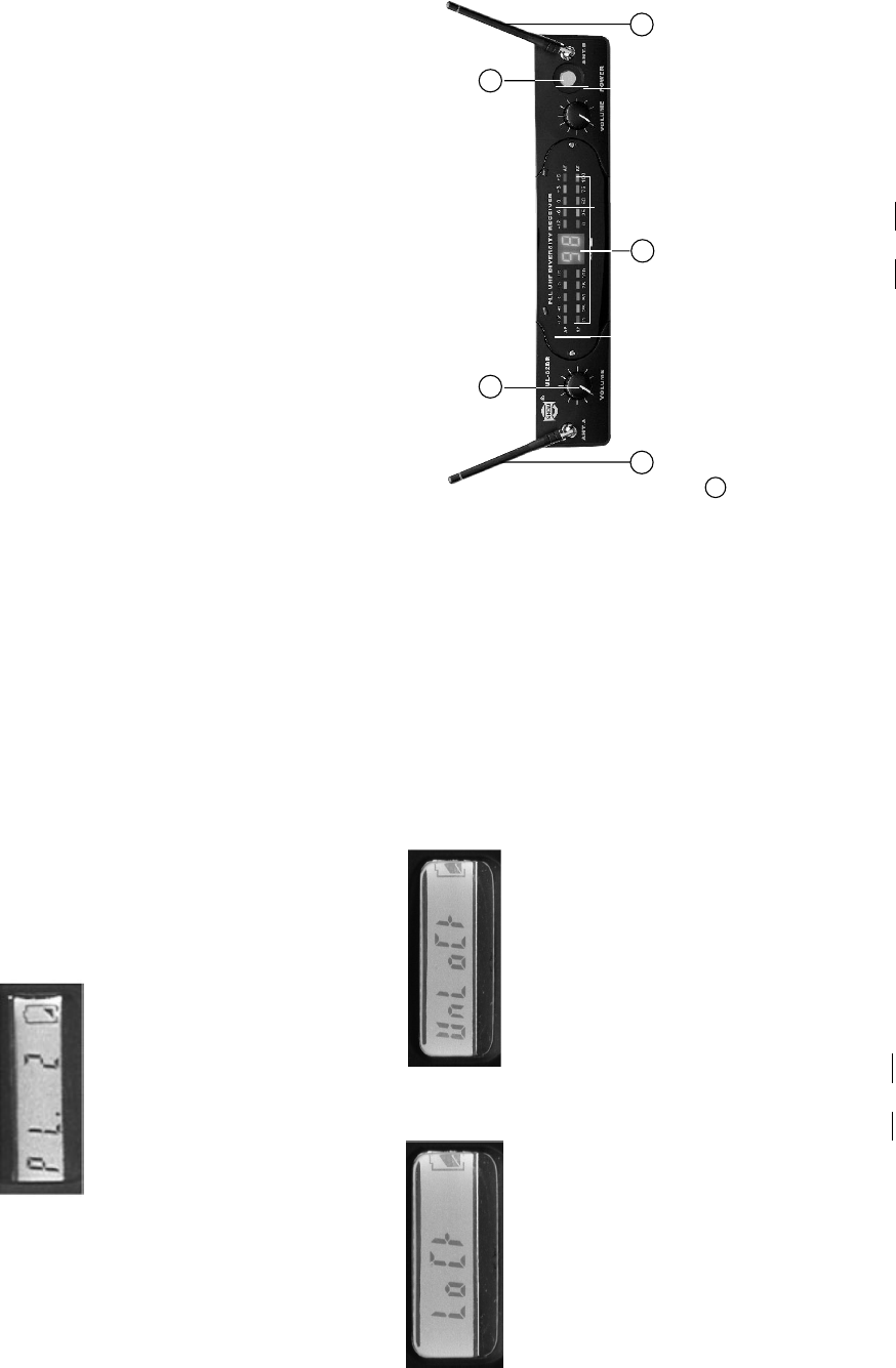
3. CONTROL ELEMENTS
3.1 UL-82DR, PLL UHF Diversity Receiver
1
2
3
44
THE FRONT PANEL
2. FEATURES
- LED indication;
- Dual antenna diversity;
- Three output level version;
- Squelch control;
4
11
- UL-82DR, PLL UHF Diversity Receiver
- Soft touch painting for comfortable use;
- Rechargeable battery design;
- Friendly interference with LCD display;
- Wide carrier frequency ranges (UHF, 470-900MHz), divided into 8 preset frequency
bands (F1 ~ F8) to comply with the country's EMC regulation;
- Up to 10 x 10, total 100 channel frequency presets;
- 3 types RF power selection;
- Mute function;
- Lock function to avoid the misaction during the application;
- Battery status display;
- Manufactured under ISO9000:2000, Ts16949 quality management system.
- UL-H/P/G series, Transmitters
- Common features
The transmitter has lock function. It can avoid the misaction during the application. You can select
lock/unlock via the SELECT key in menu mode. Please see Fig 5 and Fig 6.
Note: when the transmitter is locked, the SELECT key couldn't work at all, but you can use
CH/ON key to switch the functions. If you want to get out of lock, when the LCD shows
"LOCK", please press the SELECT key for one time, then "UNLOCK " will come out on
the LCD.
- LOCK Function
Fig 5: LOCK
Fig 6: UNLOCK
4.2.2 To make the operating frequency matched between the transmitter and the
receiver.
- Adjust from the transmitter, UL-H series
1) Check the preset frequency (preset channel) displayed on the receiver.
2) Switch on the transmitter;
3) Touch the CH/ON key slightly to select the parameters to be edited;
4) Use the Select key to set the proper channel.
Power Switch
1
It switches on/off the main power.
3.1 THE REAR PANEL
510
LED INDICATION
2
-AF INDICATION AF LEDs indicate the incoming status of the audio signal.
When "0" LED lights up, the incoming signal is optimized at unity gain. When the
"+6" LED lights up, the signal is overloaded. When only the "-20" LED lights up, the
incoming signal is just at 10% of the optimum states. If no LED lights up, there is little
even no signal being received.
-
RF INDICATION AF LEDs indicate the incoming frequency status of the radio
signal. When all the LEDs light up, the incoming signal is fully modulated and at the
optimum status. When only the 10% lights up, the incoming signal is just at 10% of the
optimum status. If no LED lights up, there is little or no signal being received.
NOTE: UL-82DR has two channels, channel 1 and channel 2. The LEDs of channel
1are on the left and the LEDs of channel 2 are on the right.
-FREQUENCY INDICATION It displays the number from 0 to 99. Each number
represents one frequency
This knob sets the audio signal level outputted through the balanced and unbalanced
output jacks on the rear panel. Turn the knob clockwise fully for the max volume, and
and turn the knob counterclockwise fully for the min volume. Each VOLUME knobs is
for one separated microphone.
VOLUME CONTROL
3
The antennas can be fully rotated for optimum placement. Generally, antenna A
and antenna B should be placed vertically for best receiving effect. Fold both antennas
inward for the convenience of transporting.
Antenna A/B
4
4.2 For the UL-H/P/G series transmitters
4.2.1 Edit The Parameter
Press and hold the CH/ON for a few seconds, then the transmitter is powered
on. Now the LCD displays the operation voltage status.
After the transmitter is switched on, touch the CH/ON key slightly to select the parameter
which you want to edit, such as the preset channel, PL(RF power level), and Lock/Unlock.
- Frequency Select
This system offers a lot of frequencies to choose in order to avoid interference.
You can select right frequency via the SELECT key in menu mode. Fig 3 is of
preset channel select. 10 10=100 different types each frequency of frequencies.
Fig 3
Fig 2
35 4 1
2
6
3.1.1 THE REAR PANEL OF UL-82DR
Use the UP key to scan the frequency presets from 0 to 99 and the DOWN key from 99 to 0.
Keep pressing these buttons for a few seconds, the channel selecting speed will be accelerated.
UP/DOWN key
1
Press the MENU key to switch channel 1 and channel 2. When channel 1 is selected, use the
UP/DOWN key to select the right frequency. Press the MENU key again, it switched to channel 2.
The frequency setting mode of channel 2 is the same as that of channel 1. Keep pressing the
MENU key for 1.5 seconds, it comes to the auto SQ mode. When the right frequency is selected,
MENU key
2
Table
No. squelch threshold
0
1
2
3
4
5
6
7
8
9
95.0dB
91.7dB
88.3dB
85.0dB
81.7dB
78.3dB
75.0dB
71.7dB
68.3dB
65.0dB
69
below a defined threshold. The squelch control on the receiver sets this threshold.
will not only cut out noise but mute quiet audio signals as well because the squelch
responds to the detected voltage and cannot distinguish between wanted signal and
noise. Besides that, a too high squelch threshold also decreases the usable range.
In the squelch control mode(Fig 2), use the UP/DOWN key to select squelch threshold.
The job of a squelch circuit is to reduce audible noise. It eliminates noise during
pauses in the audio signal by muting the receiver every time the audio level drops
Use the squelch control with care! If the squelch threshold is too high, the squelch
In order to achieve easy operation, the squelch threshold is divided into10 levels, please
refer to table.
-Squelch Control
press the MENU key once again to stop.
Note: When channel 1 and channel 2 are used at the same time, the frequency of channel 1 can
not be the same as that of channel 2 in case frequencies interfere.
XLR type connector outputs the balanced AF signal. AF OUT BALANCED 1 is for the output
signal from channel 1. AF OUT BALANCED 2 is for the output signal from channel 2.
AF OUT Balanced:
3
TS type jack outputs the unbalanced AF signal.
AF OUT unbalanced:
4
Connect the unit with the adapter for DC power supply.
DC input
5
LOW MID HI key
6
3.2 UL-H series, Handheld Transmitter
UL-83H
Massive Front Grill
Extremely rugged spring steel mesh grill to protect the capsule underneath in tough
stage or live performance.
1
LCD Display
Generally, the LCD displays the current operation status.
CH/ON Key
Keep pressing this key for a few seconds, the unit will be powered on or off. After it
is switched on, touch this key slightly to select the parameter which you want to edit,
such as the preset channel, PL (RF power level), and Lock/Unlock; In this mode, if
there is no further operation in the next few seconds, it will return to the main menu,
and the LCD displays again the current preset channel, as well as the battery status.
2
3
3
7
61
2
4
5
-Select Channel
- Turn on the transmitter
- Turn on the receiver
Press the MENU button, channel 1 is selected and the corresponding LED lights up. Press
the MENU button again, channel 2 is selected and the corresponding LED lights up.
- Select Frequency
After the first touch the MENU key, use the UP key to scan the frequency presets from 0 to 99
and the DOWN key from 99 to 0. When the right channel is searched, all the RF LEDs light up.
The volume control knob sets the audio signal level outputted through the balanced and unbalanced
output jacks on the rear panel. Turn the knob clockwise fully for the max volume, and Turn the knob
counterclockwise fully for the min volume. The volume knob on the left is for channel 1. The volume
knob on the right is for channel 2.
volume knob
- Audio Output Level Adjusting
500mA
Note: When you use CH1 and CH2 simultaneously, the frequency bands of both channels
may be interference with each other. Please change another frequency band of
any channel to avoid the problem if that situation happens.
This key controls the AF OUT Balanced output level. Set the key to LOW position for -12dB
output, MID for -6dB, HIGH for 0dB.
battery status; .
Fig 1
7 8
SELECT Key
Use this key to edit the parameters in operation mode. Keep pressing this key for a
few seconds, the unit will enter into the mute mode, repeat for unmute.
3
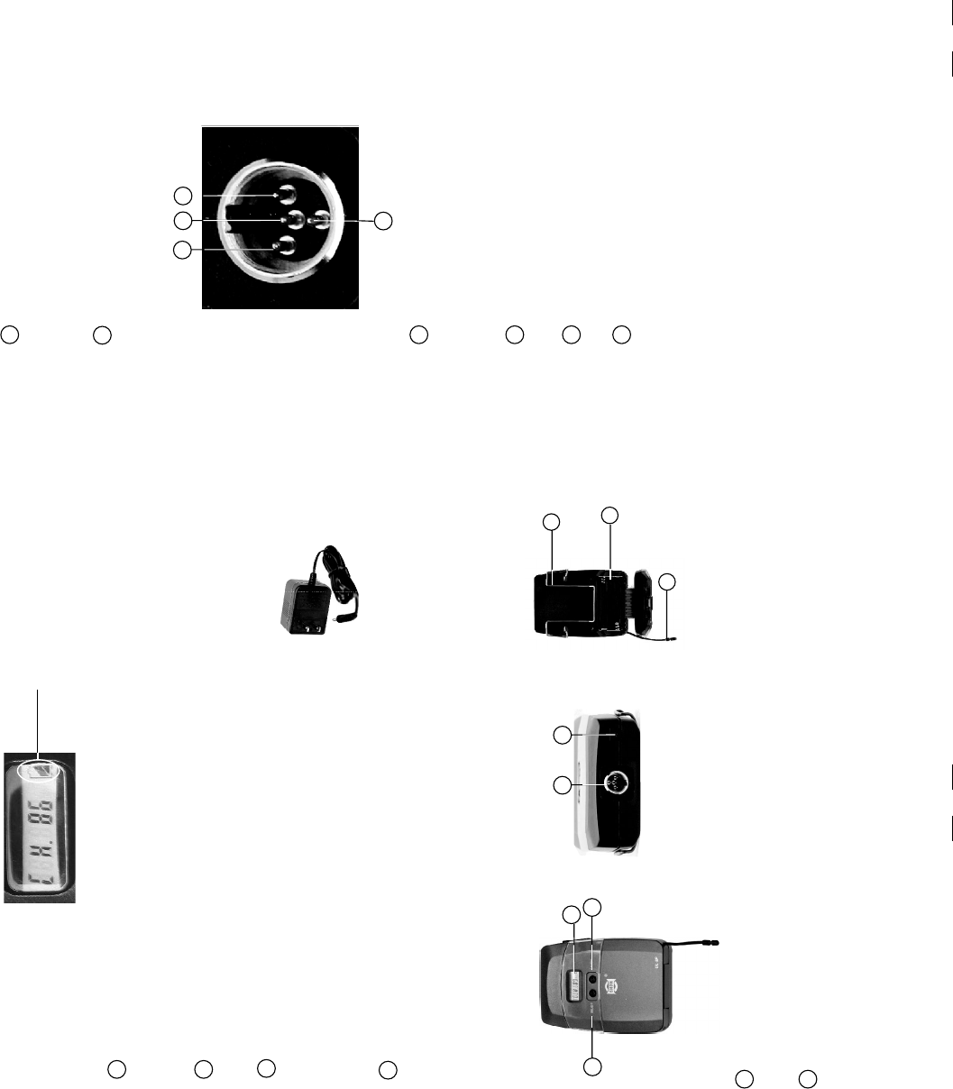
4Mini 4P connector
This connector is used to connect the unit with the clip microphones, for example, HM-38
or HM-58 condenser microphones.
3
14
2
Pin 2, GND
Pin 4, for Dynamic or condenser microphone
Antenna
It is the flexible antenna. To get effective transmission, never cover the antenna with
hand, clothes, etc. during the operation, and always position the transmitter nearby the
receiver.
8
Charge Jack
5
Battery Compartment
This unit may be powered from one pair dry or rechargeable batteries, UM3 size AA 1.5V.
6
Belt clip
It is the detachable belt clip for easy carry during the live applications.
7
Pin 3, Phantom power supply for Condenser microphone
Pin 1, for Guitar, bass and keyboards
With the rechargeable batteries put inside, use the charger (optional accessory, provided
by the manufacturer) to recharge the batteries. For the detail operation, please refer to
chapter 4.2.3, Battery replacing and charging.
- Make the right connections first
- Turn on the transmitter
- Turn on the receiver
4. OPERATION
4.1 For the UL-82DR, PLL UHF Diversity Receiver
Battery Compartment
The unit will be powered from a dry or rechargeable battery.
Charge Jack
Connect the optional recharger(see fig) with this mini
jack for battery recharging. Please make sure that it is
the rechargeable batteries inside before plug the recharger
with the mini charge jack.
5
6
3
1
2
5
4
8
6
7
3.3 UL-P/G series, Body Pack Transmitter
Antenna
The antenna is integrated into the transmitter body; to get effective RF transmission,
never cover the antenna with hand, etc.
7
CH/ON Key
Keep pressing this key for a few seconds, the unit will be powered on or off. After it
is switched on, touch this key slightly to select the parameter which you want to edit,
such as the preset channel, PL(RF power level) and Lock/Unlock. In this mode, if
there is no further operation in the next few seconds, it will return to the main menu,
and the LCD displays again the current preset channel, as well as the battery status.
2
1LCD Display
Generally, the LCD displays the current operation status.
DC 9V
SELECT Key
Use this key to edit the parameters in operation mode. Keep pressing this key for a
few seconds, the unit will enter into the mute mode, repeat for unmute.
4