SEMACONNECT 19840917 ChargePro 620 User Manual Installation Guide
SEMACONNECT INC. ChargePro 620 Installation Guide
Installation Guide

ChargePro™!620$Charging$Station!
Installation
Guide
SemaConnect Inc.
175 Admiral Cochrane Dr, Suite 300
Annapolis MD 21401
www.semaconnect.com
Version 0.9D
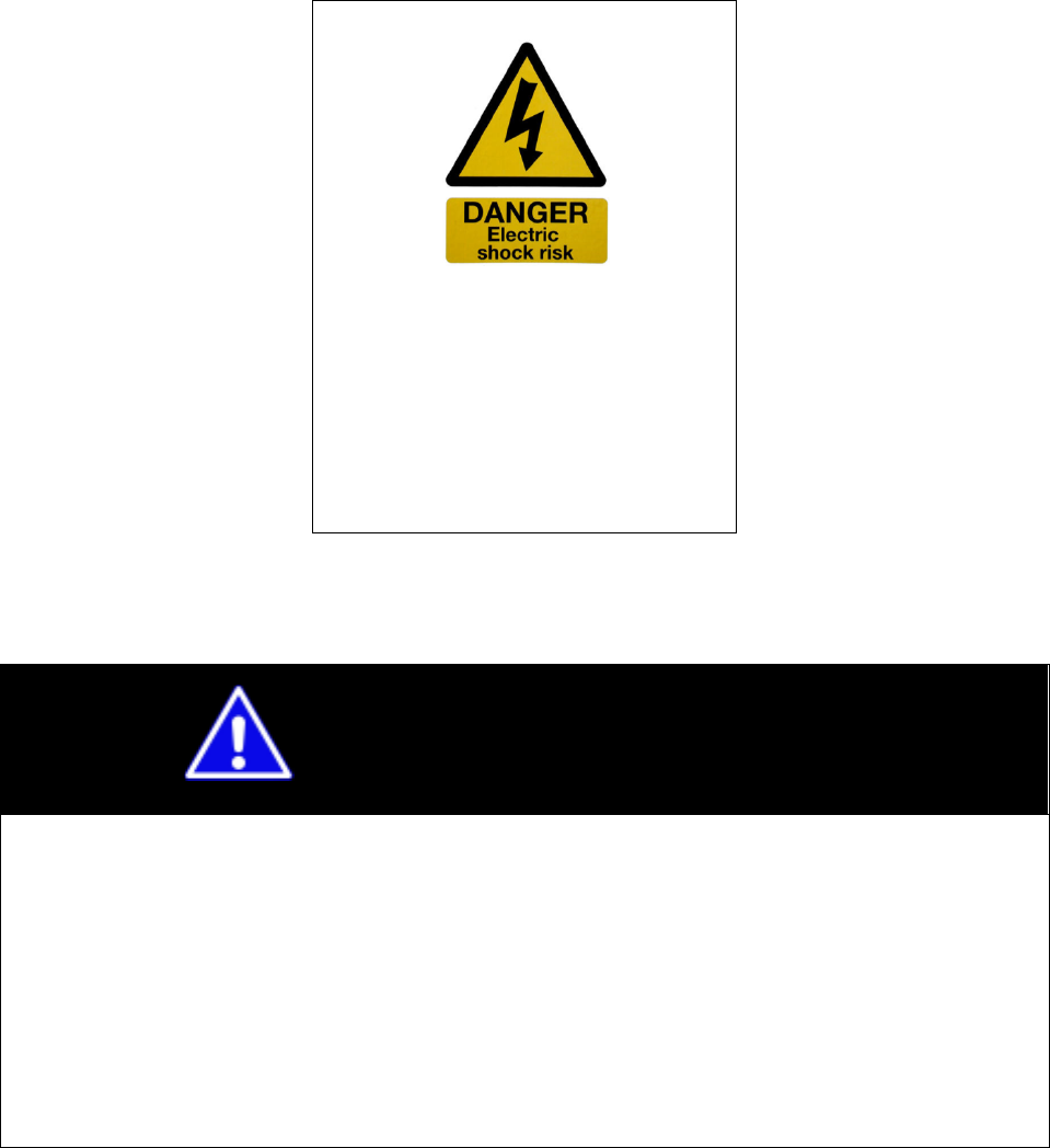
WARNING
SemaConnect recommends that only a qualified electrical professional should
install or service electric vehicle charging station equipment.
This equipment requires a heavy load electrical connection. Before beginning work,
make certain all electrical power has been turned off, such that the electrical supply
wires are disconnected from all power sources. This may require that you contact your
electric utility to disconnect power to an existing load-center. SemaConnect will not
assume responsibility for property damage or personal injury resulting from wrong use
or inadequate safety measures in servicing this equipment.
HAZARDOUS VOLTAGE
CAN CAUSE SEVERE
INJURY
OR DEATH.
Turn off Main power before
installing or servicing this device.

3 | Page
IMPORTANT SAFETY INSTRUCTIONS
SAVE THESE INSTRUCTIONS
Install Equipment in Conformance with codes
This product must be installed in accordance with the National Electrical Code (NEC) or the Canadian Electrical Code (CEC) or any
applicable local code. Before installing the equipment do check with your local electrical authority. If you have any questions or
need assistance, contact a qualified electrical contractor.
Grounding instructions
The ChargePro™ 620 Charging Station is grounded using a dedicated grounding conductor that grounds the charging station to the
power distribution panel ground.
FCC Compliance Statement
This equipment has been tested and found to comply with the limits for a Class A digital device pursuant to Part 15 of the FCC Rules.
These limits are designed to provide reasonable protection against harmful interference when the equipment is operated in a commercial
environment. This equipment generates, uses, and can radiate radio frequency energy and, if not installed and used in accordance with
the manufacturer’s instruction manual, may cause harmful interference with radio communications.
Important: Any Changes or modifications to this product not authorized by SemaConnect, Inc., could affect the EMC compliance and
revoke your authority to operate this product.
Exposure to Radio Frequency Energy: The radiated power output of the Zigbee radio and cellular modem (optional) in this device is
below the FCC radio frequency exposure limits for uncontrolled equipment.
Safety and compliance
This document provides instructions to install the ChargePro™ 620 Charging Station and should not be used for any other product.
Before installing the ChargePro™ 620 Charging Station, you should review this manual carefully and consult with a licensed contractor,
licensed electrician and trained installation expert to ensure compliance with local building practices, climate conditions, safety standards,
and state and local codes. The ChargePro™ 620 Charging Station should be installed only by a licensed contractor and a licensed
electrician and in accordance with all local and national codes and standards. The ChargePro™ 620 Charging Station should be
inspected by a qualified installer prior to the initial use. Under no circumstances will compliance with the information in this manual relieve
the user of his/her responsibility to comply with all applicable codes or safety standards. This document describes the most commonly-
used installation and mounting scenarios. If situations arise in which it is not possible to perform an installation following the procedures
provided in this document, contact SemaConnect. SemaConnect is not responsible for any damages that may occur resulting from
custom installations that are not described in this document.
No accuracy guarantee
Reasonable effort was made to ensure that the specifications and other information in this manual are accurate and complete at
the time of its publication. However, the specifications and other information in this manual are subject to change at any time
without prior notice.
Warranty information and disclaimer
Your use of, or modification to, the ChargePro™ 620 Charging Station in a manner in which the ChargePro™ 620 Charging
Station is not intended to be used or modified will void the limited warranty. Other than any such limited warranty, SemaConnect
products are provided “AS IS,” and SemaConnect and its distributors expressly disclaim all implied warranties, including any
warranty of design, merchantability, and fitness for a particular purposes and non-infringement, to the maximum extent permitted
by law.
Limitation of liability
IN NO EVENT SHALL SEMACONNECT, INC. OR ITS AUTHORIZED DISTRIBUTORS BE LIABLE FOR ANY INDIRECT,
INCIDENTAL, SPECIAL, PUNITIVE, OR CONSEQUENTIAL DAMAGES, INCLUDING WITHOUT LIMITATION, LOST PROFITS,
LOST DATA, LOSS OF USE, COST OF COVER, OR LOSS OR DAMAGE TO THE CHARGEPRO™ 620 CHARGING STATION,
ARISING OUT OF OR RELATING TO THE USE OR INABILITY TO USE THIS MANUAL, EVEN IF SEMACONNECT, INC. OR
ITS AUTHORIZED DISTRIBUTORS HAVE BEEN ADVISED OF THE POSSIBILITY OF SUCH DAMAGES.
Copyright and Trademarks
Copyright ©2010 SemaConnect, Inc. All rights reserved. This material is protected by the copyright laws of the United States and
other countries. It may not be modified, reproduced or distributed without the prior, express written consent of SemaConnect, Inc.
ChargePro™ 620 Charging Station is a trademark of SemaConnect, Inc. All other products or services mentioned are the
trademarks, service marks, registered trademarks or registered service marks of their respective owners.
!
! !

Chapter 2.Pedestal Mount
5 | Page
"#$%&!'(!)'*+&*+,!
Chapter(1.Introduction(__________________________________________________________(7!
Pre$installation,preparation, ___________________________________________________,7!
Wiring,color,code,____________________________________________________________,8!
Specifications,_______________________________________________________________,9!
Wiring,Information,__________________________________________________________,10!
Chapter(2.Pedestal(Mount(______________________________________________________(11!
Manufacturer,Supplied,Materials,for,Installation,_________________________________,11!
Installation,Overview,________________________________________________________,11!
Step,1,$,Check,boxes,for,correct,content, ________________________________________,12!
Step,2,–,Install,Anchor,Plate, __________________________________________________,14!
Step,3,$,Install,Pedestal,Unit, __________________________________________________,16!
Step,4,–,Attach,Cable,Rack,____________________________________________________,17!
Step,5,–,Install,the,Charging,Station,Head,Unit,___________________________________,18!
Chapter3.Wall(Mount( _________________________________________________________(21!
Manufacturer,Supplied,Materials,for,Installation,_________________________________,21!
Installation,Overview,________________________________________________________,21!
Step,1,$,Check,boxes,for,correct,content, ________________________________________,22!
Step,2,–,Pre$installation,preparation, ___________________________________________,25!
Step,3,$,Install,the,Wall/Pole,Mount,Bracket,_____________________________________,27!
Step,4,–,Attach,Cable,Rack,____________________________________________________,28!
Step,5,–,Install,the,Charging,Station,Head,Unit,___________________________________,29!
Chapter4.Pole(Mount(__________________________________________________________(31!
Manufacturer,Supplied,Materials,for,Installation,_________________________________,31!
Installation,Overview,________________________________________________________,31!
Step,1,$,Check,boxes,for,correct,content, ________________________________________,32!

Charging Station Installation Guide
Step,2,–,Pre$installation,preparation, ___________________________________________,35!
Step,3,$,Install,the,Wall/Pole,Mount,Bracket,_____________________________________,36!
Step,4,–,Attach,Cable,Rack,____________________________________________________,37!
Step,5,–,Install,the,Charging,Station,____________________________________________,38!
A.(Appendix( _________________________________________________________________(41!
Wall,Mount,Bracket,Dimension,________________________________________________,41!
Pedestal,mount,dimensions,(Front$view),________________________________________,42!
Bollard,mount,dimensions,(Side$view),__________________________________________,43!
Chapter 2.Pedestal Mount
7 | Page
Chapter(1.Introduction(
This document provides instructions for installing the ChargePro™ 620 Charging Station.
The ChargePro™ 620 Charging Station is shipped in two boxes.
! Box-1 – ChargePro™ 620 Charging Station Head Unit, Cable Rack and Cable Rack
screws
! Box-2 –
o If Pedestal Mount Configuration: Pedestal Unit, Anchor Plate and fasteners
o If Wall/Pole Mount Configuration: Wall/Pole Mount Bracket, Mounting
Template and fasteners
!
!
!
-.&/0*,+#%%#+0'*!1.&1#.#+0'*!
This guide assumes that the appropriate wiring, conduit and circuit protection is in place at the
installation site.
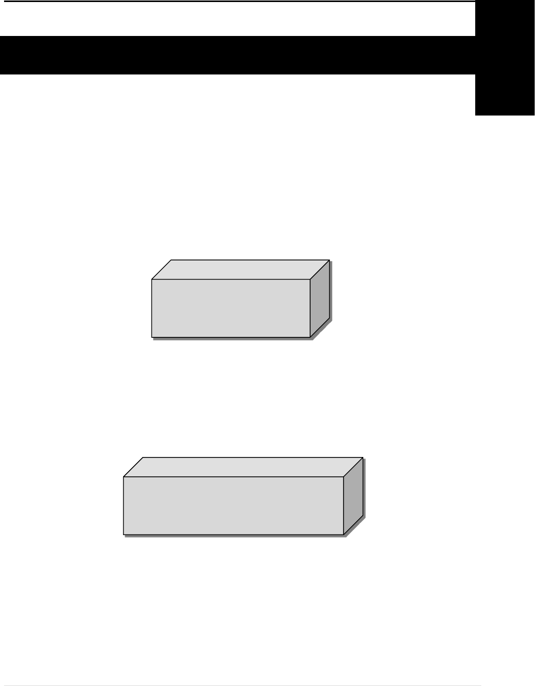
1
CHARGE PRO™ 620
CHARGING STATION
CHARGE PRO™ 620
MOUNTING ACCESSORIES
Charging Station Installation Guide
To assist in the process of preparing the installation site, carefully review the following:
! Wiring color code (Page 8)
! ChargePro™ 620 Charging Station technical specifications (Page 9)
! Wiring diagrams (Page 10)
! Wall/Pole Mounting Template (included in shipping container)
! Pedestal Unit Dimensions (Page 42 - 43)
Before installing the ChargePro™ 620 Charging Station, please review this entire document to
understand the required installation steps prior to beginning the process.
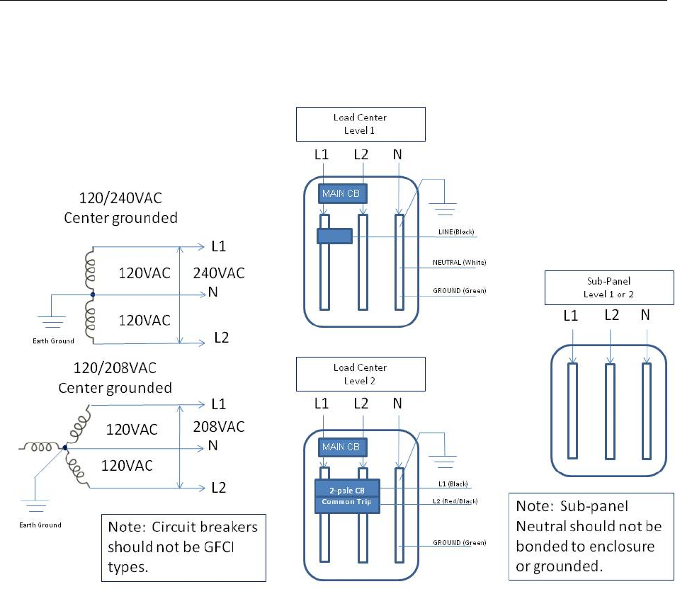
20.0*3!4'%'.!4'5&!
The illustrations and diagrams in this document reflect the Level-2 wiring color code. For Level-
1 wiring substitute the red wire with the white wire.
Strictly adhere to the wire color codes to ensure proper installation.
6&7&%/8!)9#.30*3!:+#+0'*!;8<=>?@!
Use 12 AWG wire minimum (10 AWG preferred) (ensure compliance with electrical codes).
COLOR CODE
BLACK
WHITE
GREEN
SERVICE
PHASE (L)
NEUTRAL
GROUND
6&7&%/<!)9#.30*3!:+#+0'*!;<A=>!'.!<=B>?@!
Use 10 AWG wire minimum (ensure compliance with electrical codes).
COLOR CODE
BLACK
RED
GREEN
SERVICE
PHASE A (L1)
PHASE B (L2)
GROUND

Chapter 2.Pedestal Mount
9 | Page
:1&40(04#+0'*,!
Power
Specs
AC Power Source
208/240V, center grounded, 60Hz supply
3-wire; Phase A, Phase B, ground (no neutral)
Power to Electric Vehicle
30A maximum, 7.2kW@240VAC
Branch Circuit Protector
2-pole, common trip, circuit breaker
Breaker rating125% of load (40A for 30A load)
Vehicle-to-Charger Connection
SAEJ1772 EV Connector via 18 ft Cable (supplied)
Energy Metering Accuracy
1% at 5 min intervals, 0.5% accuracy (optional)
Time-of-Use Metering
Charger support provided
Standby Power
5W
typical
Safety
Specs
Personnel Protection System
Charging Circuit Interrupting Device (CCID)
Trip Threshold 5 mA, CCID5 per UL2231-2
Automatic³Unplug´Detection
Charger output voltage
terminated
Remote notification via SMS or email(owner configured)
Codes and Standards Compliance
Listed to UL2231-1,-2 and UL2594
NEC Article 625 compliant
Network
Specs
Local Area Network
2.4GHz 802.15.4 dynamic mesh network
Wide Area Network
Commercial CDMA or GPRS cellular network
Network Communication Protocol
TCP/IP
Network Security
HTTPS;128-bit AES Encryption
Maximum Charging Station per LAN
128
Smart Card Reader
ISO15693 compliant
Charger Status Indicating
Displays
LED Array
270 deg visibility, multi-color visual status indication
LCD Screen
2 lines, 16 characters per line, backlit
Environmental
Specs
Outdoor Rated
NEMA 3 per NEMA 250-1997, IP44 per IEC 60529
Operating H
umidity
Upto 95% non-condensing
Operating Temperature
-30 deg C to +50 deg C ambient
Other S
pecs
Surge Protection
6kV@3,000A per UL 2231-2,Extraprotection optional
EMI Compliance
FCC Part15 Class A
Dimensions
18in high x 6 in wide x 6 in deep
Charging Station Installation Guide
20.0*3!C*('.D#+0'*!

Chapter 2.Pedestal Mount
11 | Page
)9#1+&.!<E-&5&,+#%!F'G*+!
This chapter covers the installation of the ChargePro™ 620
Charging Station using a Pedestal Unit.
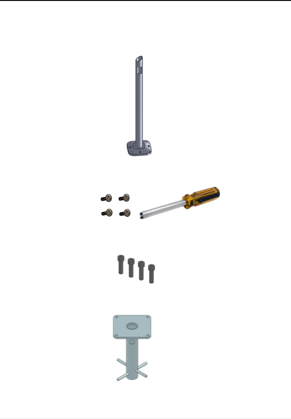
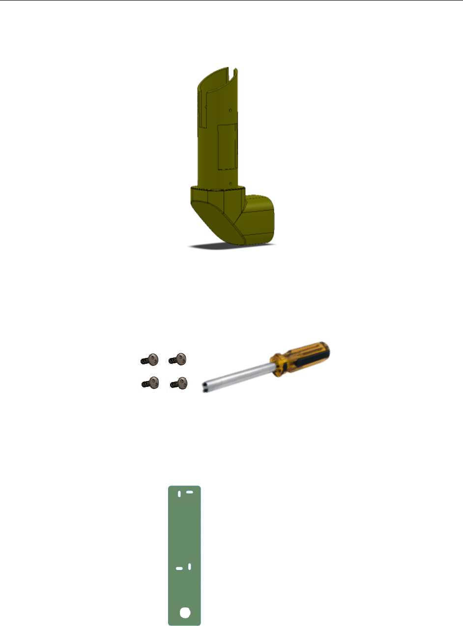
F#*G(#4+G.&.!:G11%0&5!F#+&.0#%,!('.!C*,+#%%#+0'*!
! The following items can be found in Box- 1
o ChargePro™ 620 Charging Station Head Unit
o Cable Rack and Cable Rack mounting screws (4ea)
! The following items can be found in Box- 2
o ChargePro™ 620 Charging Station Pedestal Unit
o Charging Station Anchor Plate
o Anchor Bolts
o Tamper- resistant screwdriver
C*,+#%%#+0'*!H7&.70&I!!
1. Check the boxes for correct content
2. Install the Anchor Plate
3. Install the Pedestal Unit
4. Attach the Cable Rack
5. Install the Charging Station Head Unit
The steps are further detailed in the remainder of this chapter.
2
Charging Station Installation Guide
!
:+&1!8!/!)9&4J!$'K&,!('.!4'..&4+!4'*+&*+!
The ChargePro™ 620 Charging Station shipping boxes contain:
Box-1 - Charging Station
! ChargePro™ 620 Charging Station Head Unit
! Cable Rack
! Cable Rack mounting screws (4ea)
Chapter 2.Pedestal Mount
13 | Page
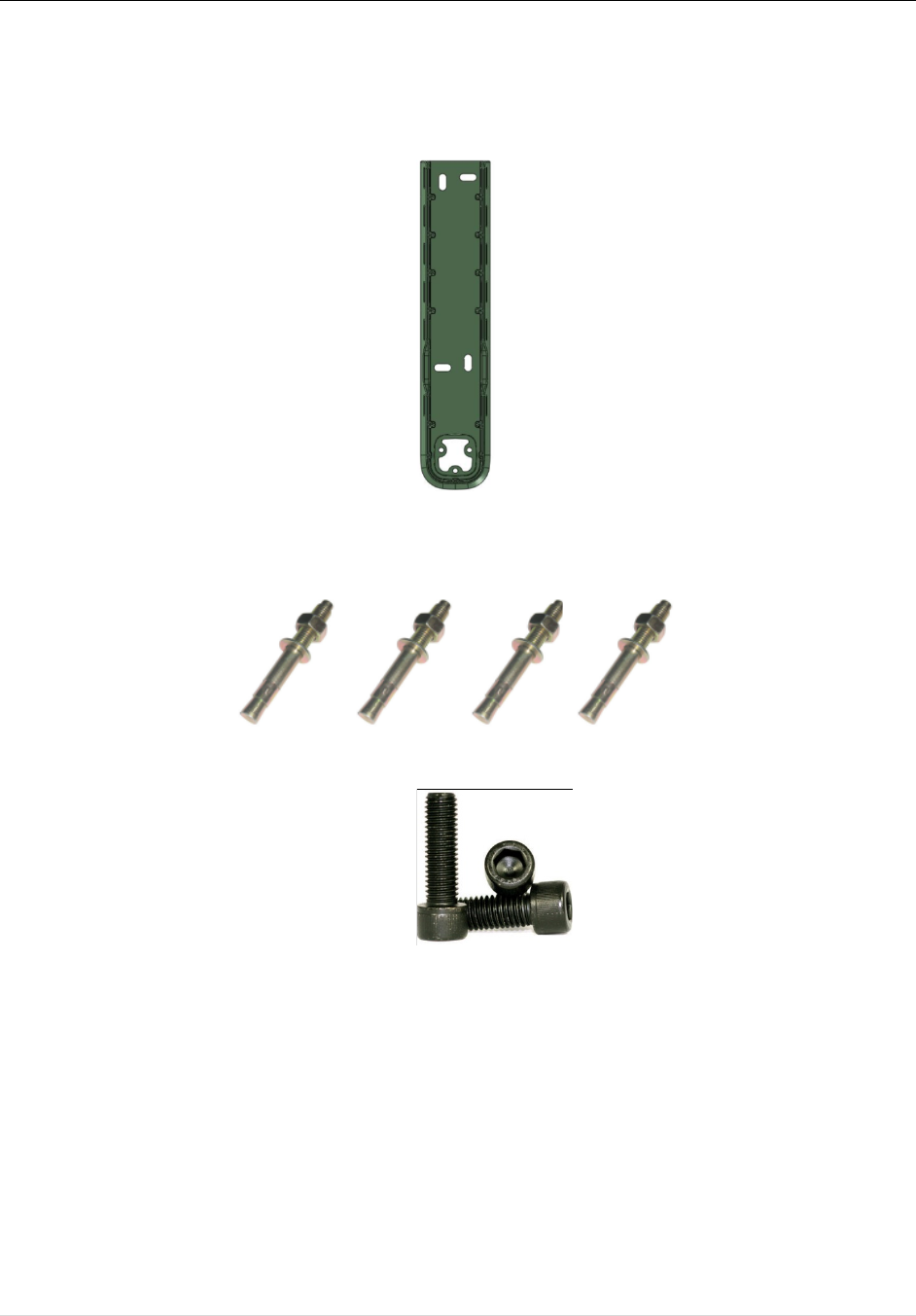
Box-2 – Mounting Accessories
! ChargePro™ 620 Charging Station Pedestal Unit
! Head Unit mounting screws (4ea) with tamper-resistant screwdriver
! Pedestal Unit anchor bolts (4ea)
! Anchor Plate
!
!
Charging Station Installation Guide
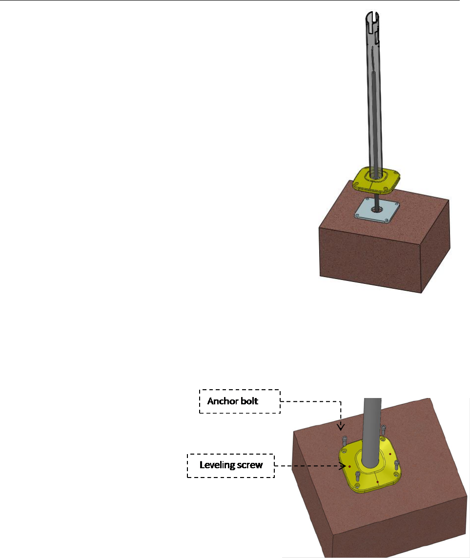
:+&1!<!L!C*,+#%%!M*49'.!-%#+&!
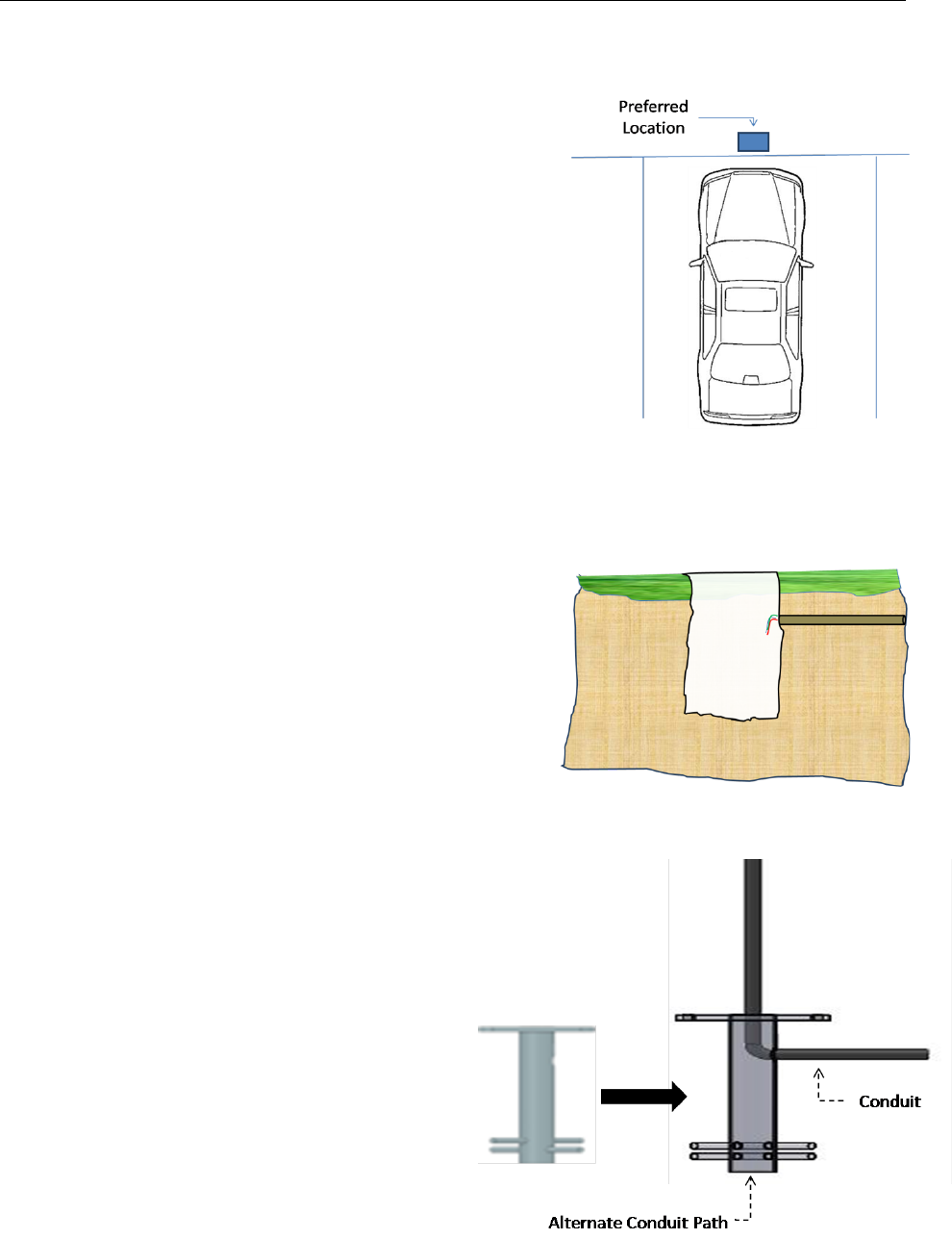
:0+&!:&%&4+0'*!
Select the location for the charging station. To mount the
charging station, first prepare a concrete pad such that it is
properly aligned to the parking space.
The concrete pad should be positioned such the distance
between the charging station and electric vehicle is sufficient to
minimize likelihood of damage (suggested min. 3 ft).
:0+&!-.&1#.#+0'*!
The Anchor Plate is 18 inches in height; therefore it is
recommended that the concrete pad is at least 24 inches in
depth (check local codes).
In preparation for the concrete pad, excavate to a depth of
24 inches, length 18 inches (recommended), width 18
inches (recommended). Trench for electrical conduit into
this hole (check local codes).
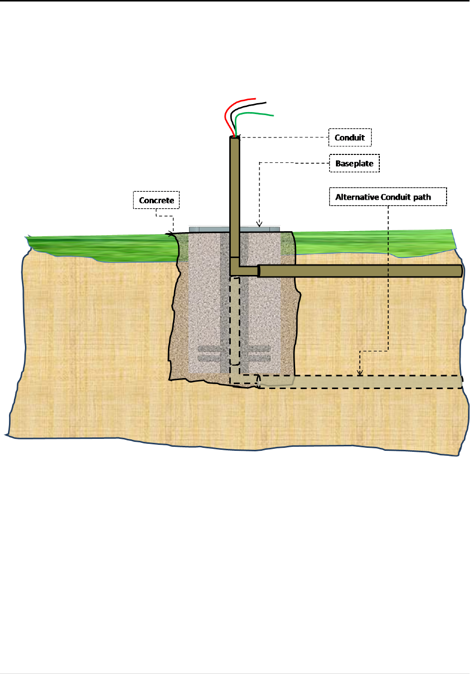
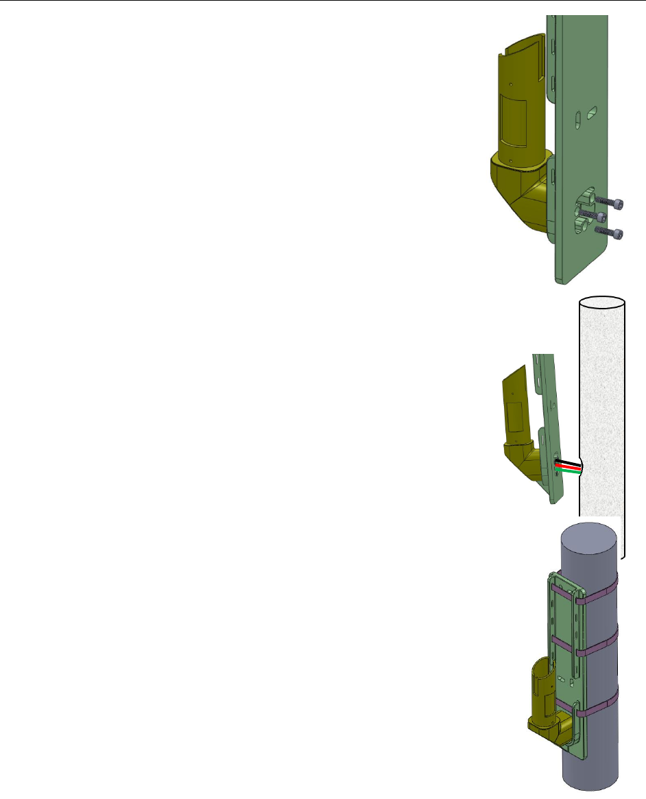
Prepare the Anchor Plate
To prepare the Anchor Plate for installation, run
conduit through the anchor as illustrated in the
diagram. The conduit should run either through
the side hole in the Anchor Plate post or through
the bottom of the post itself. The conduit should
extend 2.5ft above the anchor plate (check local
codes).
Chapter 2.Pedestal Mount
15 | Page
Next, pass wires through the conduit such that the free end of the wires extends at least 12 inches
from the opening, giving enough slack to facilitate the connection to the device.
Also, note the alternative conduit path.
Pour concrete to fill the hole as shown above in the diagram. As the concrete fills up, with the
help of a Level, ensure that the base plate is parallel to the ground.
Allow sufficient time for the concrete to harden before going to the next step.
!
!
Charging Station Installation Guide
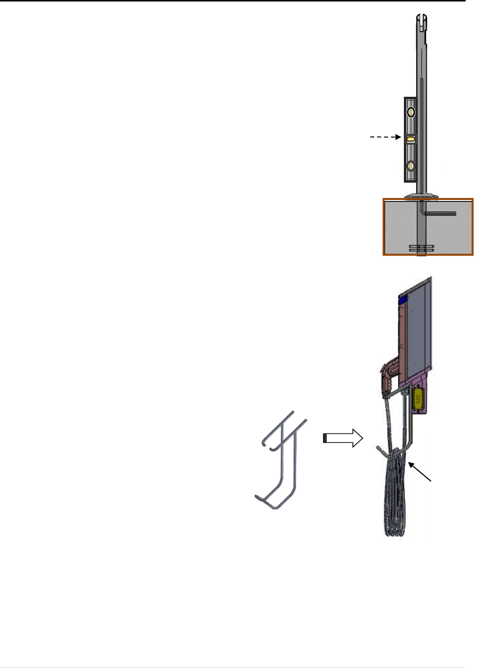
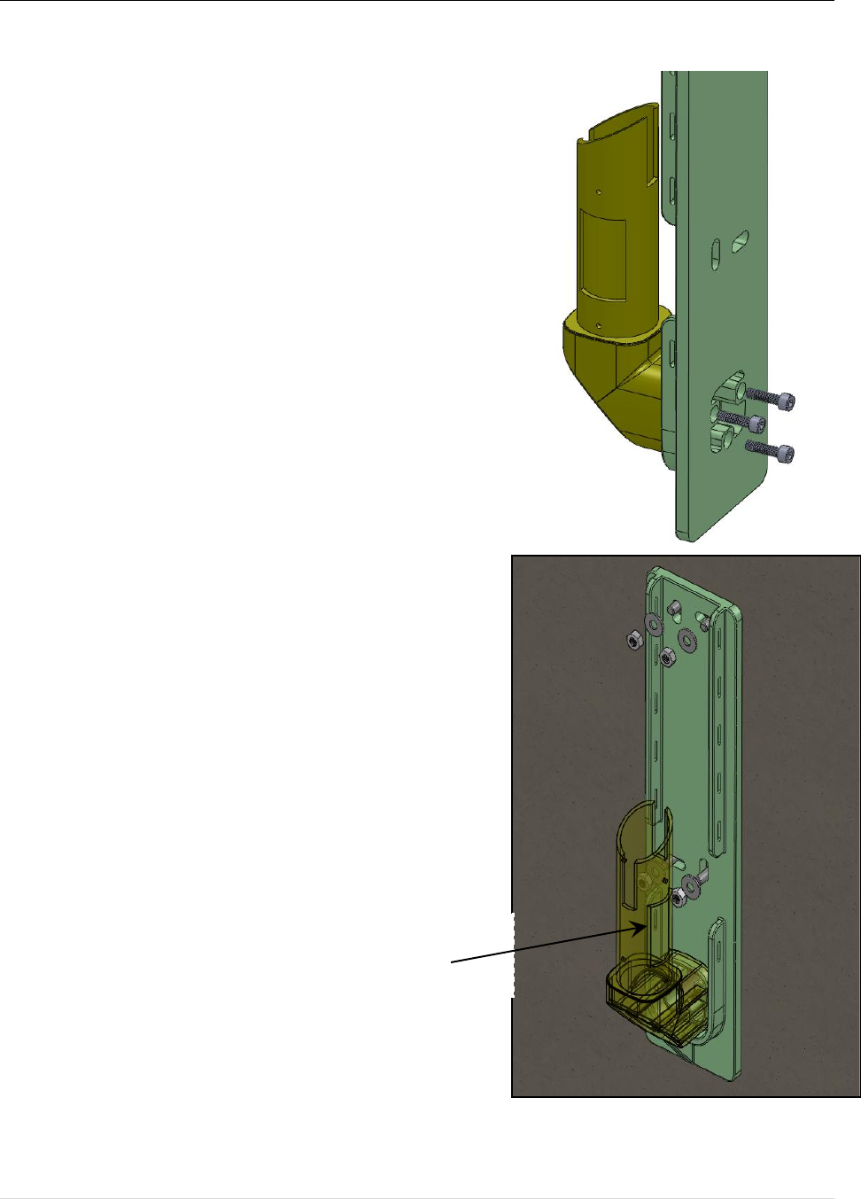
:+&1!N!/!C*,+#%%!-&5&,+#%!O*0+!
C*,&.+!+9&!-&5&,+#%!
Now we are ready to install the Pedestal Unit. Carefully place
the Pedestal Unit over the conduit and wires as illustrated in
the diagram.
Place the Pedestal Unit on the Anchor Plate such that the bolt
holes are aligned.
Ensure that the electric wires can be easily accessed through
the access window provided in the Pedestal’s top section.
M*49'.!$'%+,!P!6&7&%0*3!,4.&I,!
First insert anchor bolts and secure with one or two turns, but
do not tighten.
Note: The leveling screws that can be
found on four sides are used to adjust
for plumb.
Chapter 2.Pedestal Mount
17 | Page
Q*,G.&!-&5&,+#%!0,!-%GD$!
Adjust leveling screws to make pedestal plumb (check with
Level at two points separated by 90 degrees).
Tighten the #*49'. bolts
Gradually tighten anchor bolts to secure the Pedestal Unit
to the Anchor Plate. Re-check for plumb.
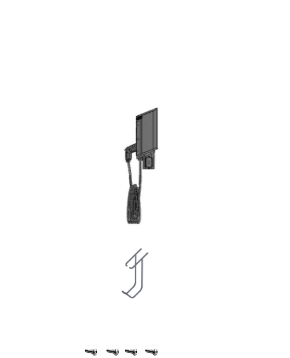
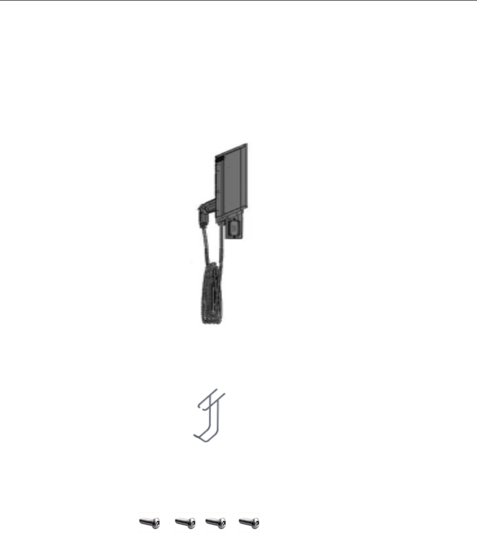
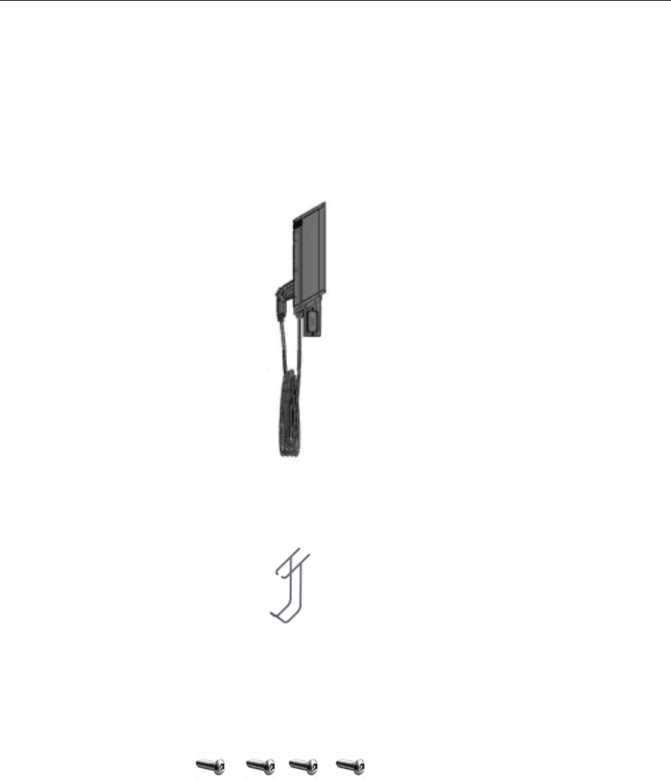
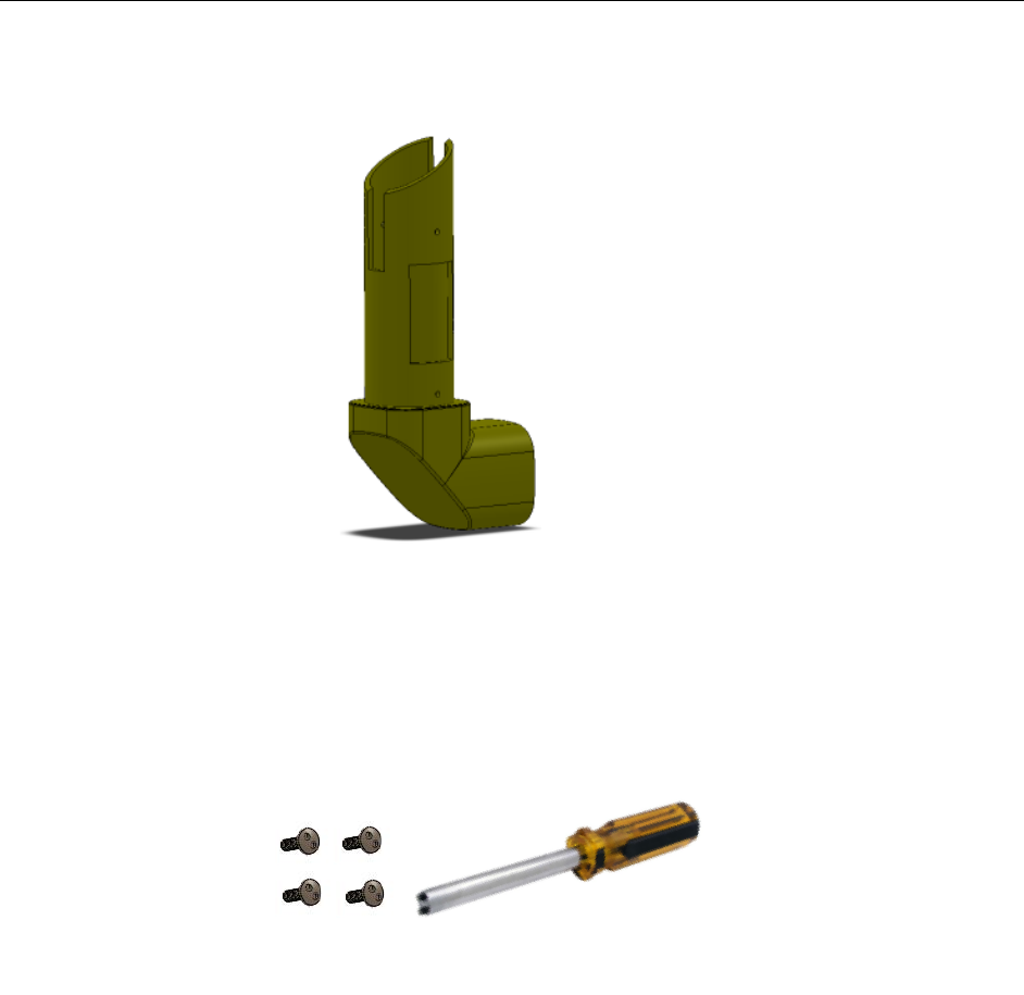
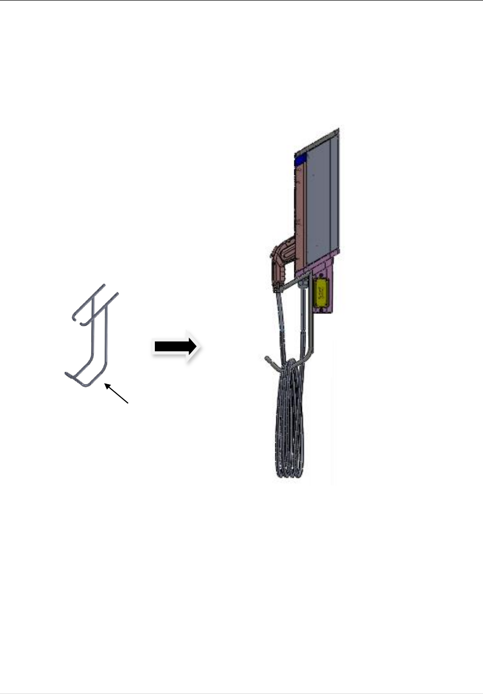
:+&1!A!L!M++#49!)#$%&!R#4J!
Attach the Cable Rack to the underside of the Charging
Station Head Unit (see diagram) using the four (4) Cable
Rack screws. After tightening screws, check that the Cable
Rack is secure and is firmly attached to the Head Unit.
Cable
Rack
Level
Charging Station Installation Guide
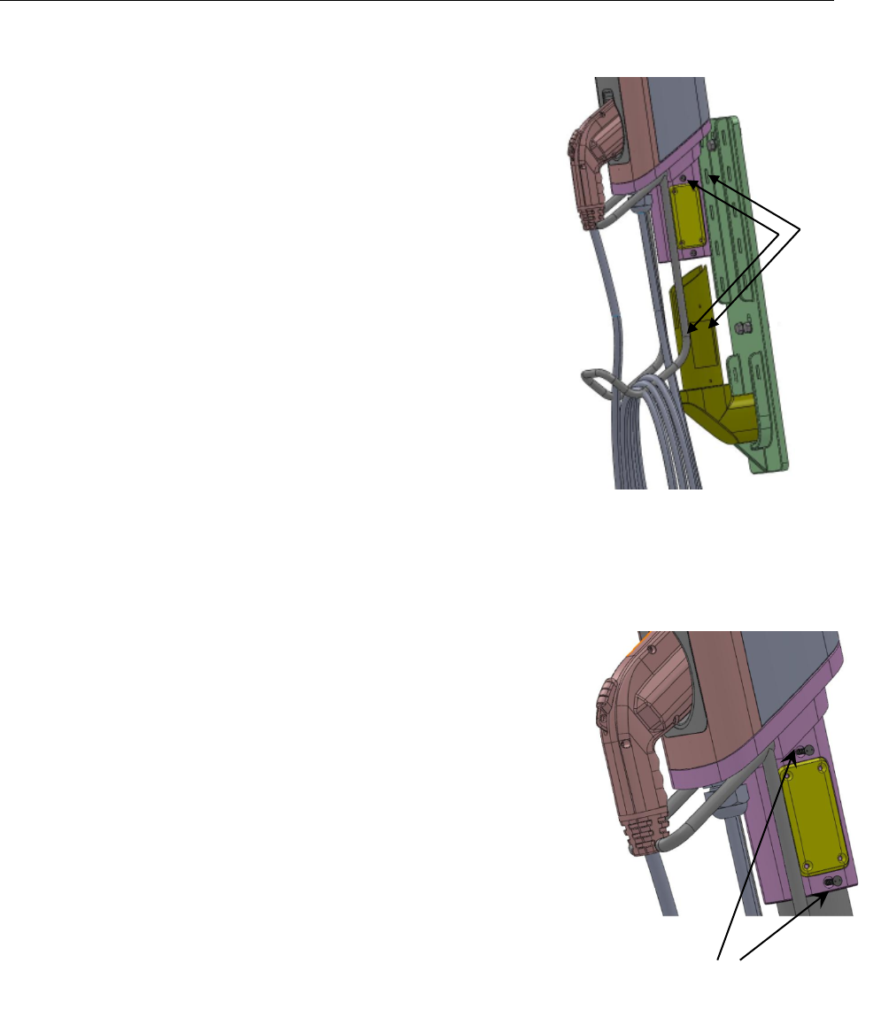
Access Panel
Tamper-
resistant
Screws
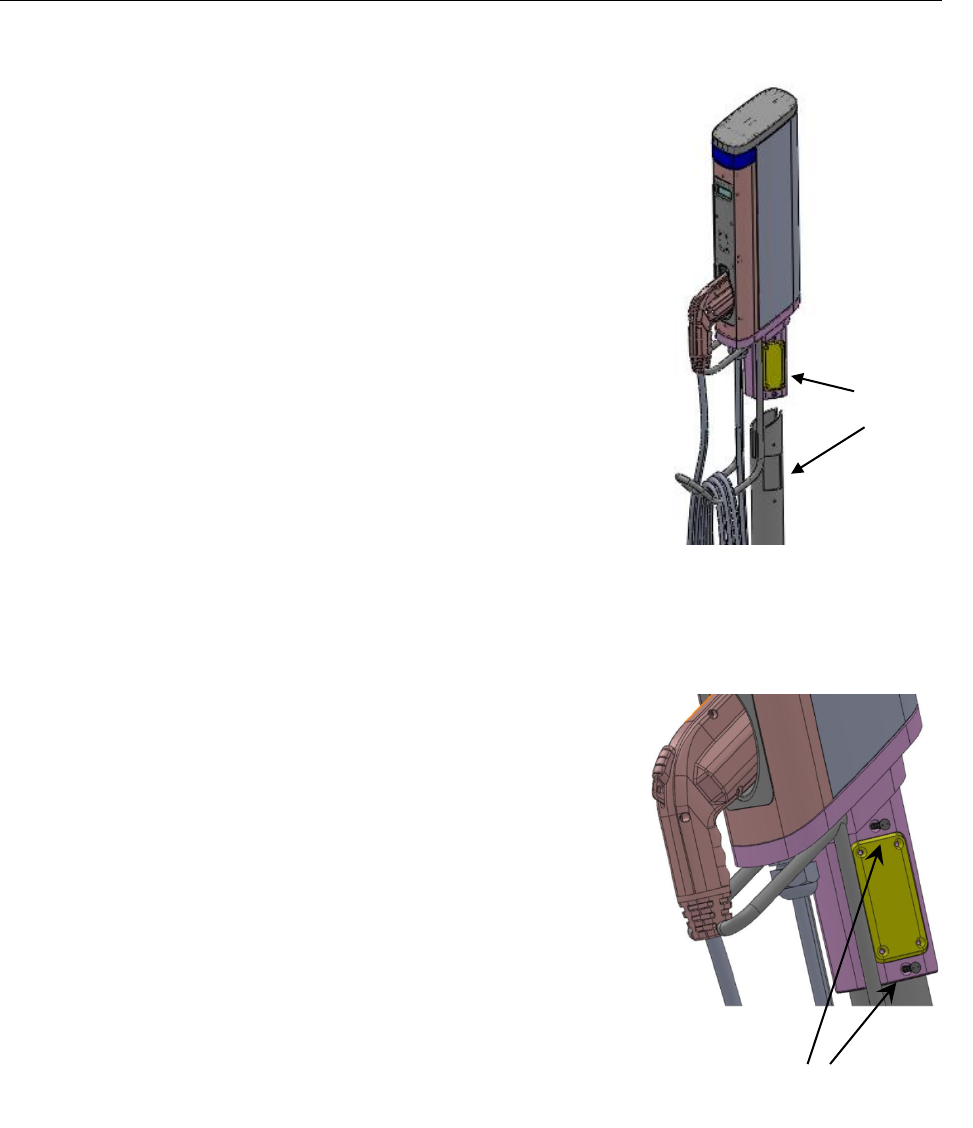
:+&1!S!L!C*,+#%%!+9&!)9#.30*3!:+#+0'*!T!O*0+!
Next install the ChargePro™ 620 Charging Station Head Unit onto the
Pedestal.
!
F'G*+!+9&!49#.30*3!,+#+0'*!9!G*0+!
Carefully insert the charging station head unit on top of the
pedestal as shown in the illustration. The access panel cut-outs
on the Pedestal Unit and Head Unit should be aligned.
!
U0.D%V!(#,+&*!+9&!49#.30*3!,+#+0'*!
As illustrated, attach the Charging Station Head Unit to the
Pedestal Unit with the four tamper-resistant screws provided
(two on each side). Ensure the charging station is plumb using
a level. Check that the Head Unit is now securely fastened to
the Pedestal.
Chapter 2.Pedestal Mount
19 | Page
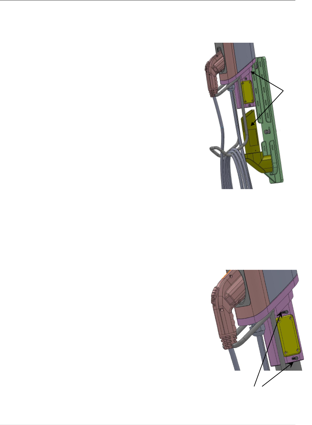
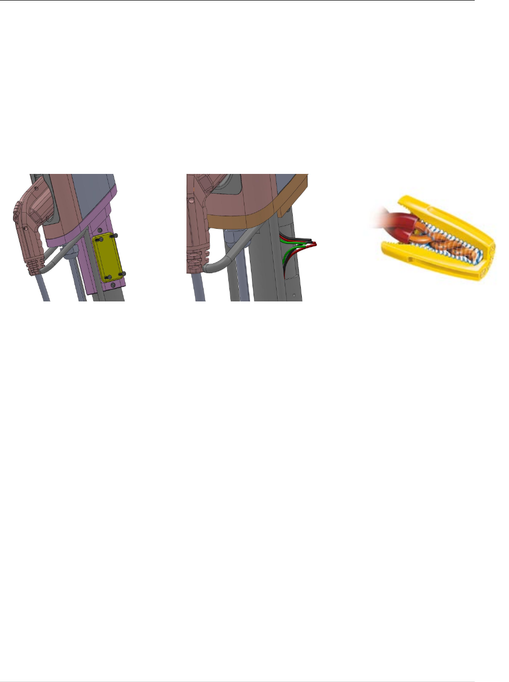
)'**&4+0*3!+9&!I0.&,!
Open the Access Panel by removing the four screws. Locate and access the wires inside.
Carefully pull these wires a few inches outside of the access panel, to reveal 3 wires coming
from the Charging Station Head Unit (for Level-2 charging stations the color codes are Red,
Black and Green) and 3 wires from the Pedestal with the same color combination. Remove the
insulation on each wire and prepare to connect those using wire-nuts.
Match the wires using the colors (Black-Black, Green-Green & Red-Red) and connect them
using wire nuts as illustrated above. Once connected, slowly insert the wires into the device and
replace the access panel cover using the screws previously removed.
Caution: Refer to the wire color codes (Page 8) and strictly adhere to this convention while
connecting the charging station and electrical supply wires. Incorrect wiring can lead to an
electrical hazard.
-'I&.!O1!
Congratulations!
You have now finished the installation of the ChargePro™
620 Charging Station! You can now power up the device.

Charging Station Installation Guide

21 | Page
)9#1+&.NE2#%%!F'G*+!
This chapter covers the installation of the ChargePro™ 620 Charging Station on a wall.
F#*G(#4+G.&.!:G11%0&5!F#+&.0#%,!('.!C*,+#%%#+0'*!
! The following items can be found in Box-1
o ChargePro™ 620 Charging Station Head Unit
o Cable Rack and Cable Rack mounting screws
! The following items can be found in Box-2
o Wall/Pole Mount Bracket Plate
o Wall/Pole Mount Bracket Post
o Tamper-resistant screwdriver
o Wall Mount Template
C*,+#%%#+0'*!H7&.70&I!!
1. Check the boxes for correct content
2. Pre-installation preparation
3. Install Wall/Pole Mount Bracket
4. Attach the Cable Rack
5. Install the Charging Station Head Unit
The steps are further detailed in the remainder of this chapter.
3
Charging Station Installation Guide
:+&1!8!/!)9&4J!$'K&,!('.!4'..&4+!4'*+&*+!
The ChargePro™ 620 Charging Station boxes contain:
Box-1 - Charging Station Head Unit
! ChargePro™ 620 Charging Station Head Unit
! Cable Rack
! Cable Rack mounting screws (4ea)

23 | Page
Box-2 – Mounting Accessories
! ChargePro™ 620 Charging Station Wall/Pole Mount Bracket Plate
! Wall/Pole Mount Bracket anchor bolts (4ea)
! Wall/Pole Mount Bracket Post screws (3ea)
Charging Station Installation Guide
! Wall/Pole Mount Bracket Post
! Head Unit mounting screws (4ea) with tamper-resistant screwdriver
! Wall Mount Template
25 | Page
:+&1!<!L!-.&/0*,+#%%#+0'*!1.&1#.#+0'*!
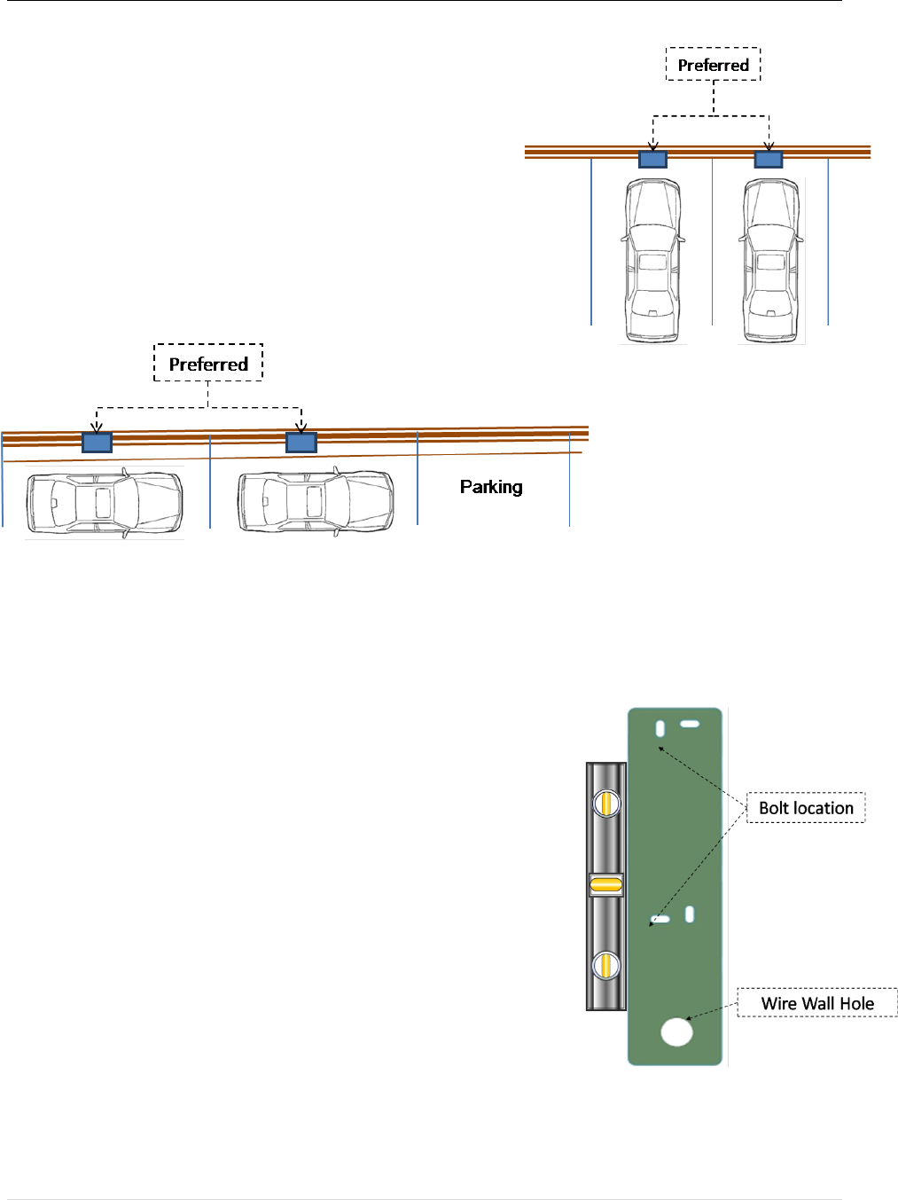
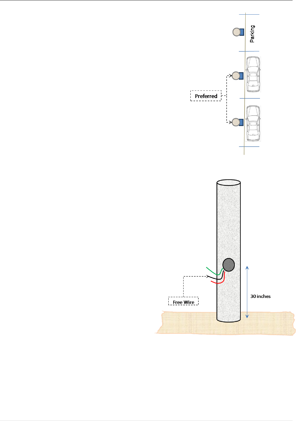
:0+&!,&%&4+0'*!
The charging station should be positioned such the
distance between the charging station and electric vehicle
is sufficient to minimize likelihood of damage (suggested
min. 3 ft).Two alternatives are illustrated here.
!
!
!
!
!
!
!
-.&1#.0*3!+9&!I#%%!
At the selected location, place the wall-mount template on the
wall such that the top of the template is at a height of 49 inches
(Check local codes). The equipment should be installed at least
18 inches above the floor.
With the help of a Level, ensure the template is in an upright
position. Mark locations for the bolt locations. If running wire
inside wall also mark Wire Wall Hole.
Charging Station Installation Guide
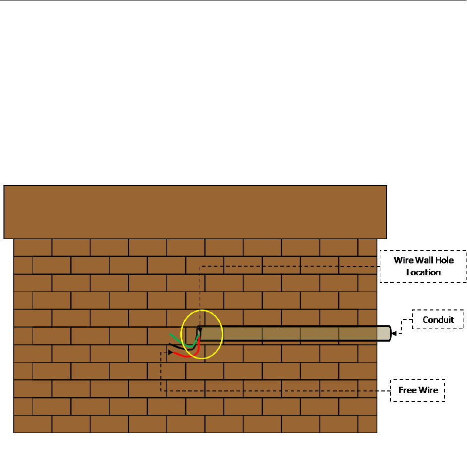
If solid concrete or brick wall, drill ½ inch diameter holes to a depth of 4 inches for the anchor
bolts provided. For walls other than concrete, solid block or brick, use fasteners appropriate for
material.
Now, run conduit up to wire wall hole location previously marked on the wall. Run the wires
through this conduit up to wire wall hole location with at least 18” (+wall thickness) free wire.
See illustration for clarity.
NOTE: If the conduit is run on the same side of the wall as the charging station the wires are
then run through the opening on the side of the Wall/Pole Mount Bracket Post.
27 | Page
:+&1!N!/!C*,+#%%!+9&!2#%%W-'%&!F'G*+!X.#4J&+!
-.&1#.&!+9&!2#%%W-'%&!F'G*+!X.#4J&+!
First, prepare the wall bracket to be bolted on to the wall.
Firmly attach the Wall/Pole Mount Bracket Plate to the
Wall/Pole Mount Bracket Post using the Wall/Pole Mount
Post screws (3ea). Make sure that the Post is securely
attached to the Wall Mount Plate.
F'G*+!X.#4J&+!'*!+9&!$'%+,!
Now hang the Wall/Pole Mount Bracket on the anchor
bolts embedded in the wall, while carefully running the
wires through the Post. Ensure the wires run all the way to
the access panel opening.
Finish attaching bracket by securing nuts on bolts with
washers.
!
! !
Access Panel
& Wires
Charging Station Installation Guide
:+&1!A!L!M++#49!)#$%&!R#4J!
Attach the cable rack to the underside of the charging station as illustrated, using the four
(4) cable rack screws. Ensure the rack has been attached properly and can carry the
weight of the cable that will be placed on the it.
!
Cable Rack
29 | Page
:+&1!S!L!C*,+#%%!+9&!)9#.30*3!:+#+0'*!T!O*0+!
Now we are ready to install the charging station.
!
F'G*+!+9&!49#.30*3!,+#+0'*!
Carefully insert the Charging Station Head Unit on top of the
Wall Mount Bracket Post as shown in the diagram. The access
panel on the Charging Station Head Unit should be aligned with
the panel on the Wall/Pole Mount Bracket Post.
U0.D%V!(#,+&*!+9&!49#.30*3!,+#+0'*!
Attach the Charging Station Head Unit to the Post using the
four (4) tamper-resistant screws provided (two on each side).
Ensure the charging station is plumb using a Level. Check that
the Head Unit is now securely fastened to the Post.
Tamper-
resistant
Screws
Access
Panel
Charging Station Installation Guide
)'**&4+0*3!+9&!I0.&,!
Open the Access Panel by removing the four (4) screws. Locate and access the wires inside.
Carefully pull these wires a few inches outside of the access panel, to reveal 3 wires coming
from the Charging Station Head Unit (for Level-2 charging stations the color codes are Red,
Black and Green) and 3 wires from the Pedestal with the same color combination. Remove the
insulation on each wire and prepare to connect those using wire-nuts.
Match the wires using the colors (Black-Black, Green-Green & Red-Red) and connect them
using wire nuts as illustrated above. Once connected, slowly insert the wires into the device and
replace the access panel cover using the screws previously removed.
Caution: Refer to the wire color codes (Page 8) and strictly adhere to this convention while
connecting the charging station and electrical supply wires. Incorrect wiring can lead to an
electrical hazard.
-'I&.!O1!
Congratulations!
You have now finished the installation of the wall mounted
ChargePro™ 620 Charging Station!
You can now power up the device.

31 | Page
)9#1+&.AE-'%&!F'G*+!
This chapter covers the installation of the ChargePro™ 620 Charging Stations on a pole mount.
F#*G(#4+G.&.!:G11%0&5!F#+&.0#%,!('.!C*,+#%%#+0'*!
! The following items can be found in Box- 1
o ChargePro™ 620 Charging Station Head Unit
o Cable Rack and Cable Rack mounting screws (4ea)
! The following items can be found in Box-2
o Wall/Pole Mount Bracket Plate
o Wall/Pole Mount Bracket Post
o Tamper-resistant screwdriver
o Wall Mount Template (not needed for Pole Mount configuration)
! The following Items are to be supplied by the Installer
o Straps to secure the Wall/Pole Mount Bracket Plate
C*,+#%%#+0'*!H7&.70&I!!
1. Check the boxes for correct content
2. Pre-installation preparation
3. Install Wall/Pole Mount Bracket
4. Attach the Cable Rack
5. Install the Charging Station Head Unit
The steps are further detailed in the remainder of this chapter.
4
Charging Station Installation Guide
:+&1!8!/!)9&4J!$'K&,!('.!4'..&4+!4'*+&*+!
The ChargePro™ 620 Charging Station boxes contain:
Box-1 - Charging Station
! ChargePro™ 620 Charging Station Head Unit
! Cable Rack
! Cable Rack mounting screws (4ea)
33 | Page
Box-2 – Mounting Accessories
! ChargePro™ 620 Charging Station Wall/Pole Mount Bracket Plate
! Wall/Pole Mount Bracket anchor bolts (4ea)
! Wall/Pole Mount Bracket Post screws (3ea)
Charging Station Installation Guide
! Wall/Pole Mount Bracket Post
! Head Unit mounting screws with tamper-resistant screwdriver
!
35 | Page
:+&1!<!L!-.&/0*,+#%%#+0'*!1.&1#.#+0'*!
:0+&!,&%&4+0'*!
The charging station should be positioned such the distance
between the charging station and electric vehicle is sufficient
to minimize likelihood of damage (suggested min. 3 ft). Two
alternatives are illustrated here.
!
-.&1#.&!+9&!1'%&!
1. On the selected pole cut 1 inch diameter hole
30 inches from the ground level (Check local
codes).
2. Run the wires from the distribution panel to
the opening created on the pole as shown in
illustration. Ensure that that free end of the wire
extends at least 18” outside the pole.
NOTE: Ideally, the conduit should run internally through the pole from the distribution panel to
the wire-hole location. However, if external conduit is used, there is an opening on the side of the
Wall/Pole Mount Bracket Post for the wires.
!
Charging Station Installation Guide
:+&1!N!/!C*,+#%%!+9&!2#%%W-'%&!F'G*+!X.#4J&+!
-.&1#.&!+9&!2#%%W-'%&!F'G*+!X.#4J&+!
First, prepare the wall bracket to be bolted on to the pole.
Firmly attach the Wall/Pole Mount Bracket Plate to the
Wall/Pole Mount Bracket Post using the Wall/Pole Mount
Post screws (3ea). Make sure that the Post is securely
attached to the Wall/Pole Mount Plate.
-#,,!+9&!I0.&,!+9.'G39!+9&!$.#4J&+!
Run the wires through the Wall/Pole Bracket and Post.
:+.#1!+9&!$.#4J&+!+'!+9&!1'%&!
Now place the Wall/Pole Mount Bracket against the pole
and secure it with at least 3 straps as illustrated.
Place a Level alongside the Wall/Pole Mount Bracket, to
ensure the assembly is in an upright position.
Now, fasten the straps to ensure that the bracket is secure.
!
!
!
37 | Page
:+&1!A!L!M++#49!)#$%&!R#4J!
Attach the Cable Rack to the underside of the charging station as illustrated, using the
four (4)Cable Rack screws. Ensure the rack has been attached properly and can carry the
weight of the cable that will be placed on the it.
!
!
! !
Cable Rack
Charging Station Installation Guide
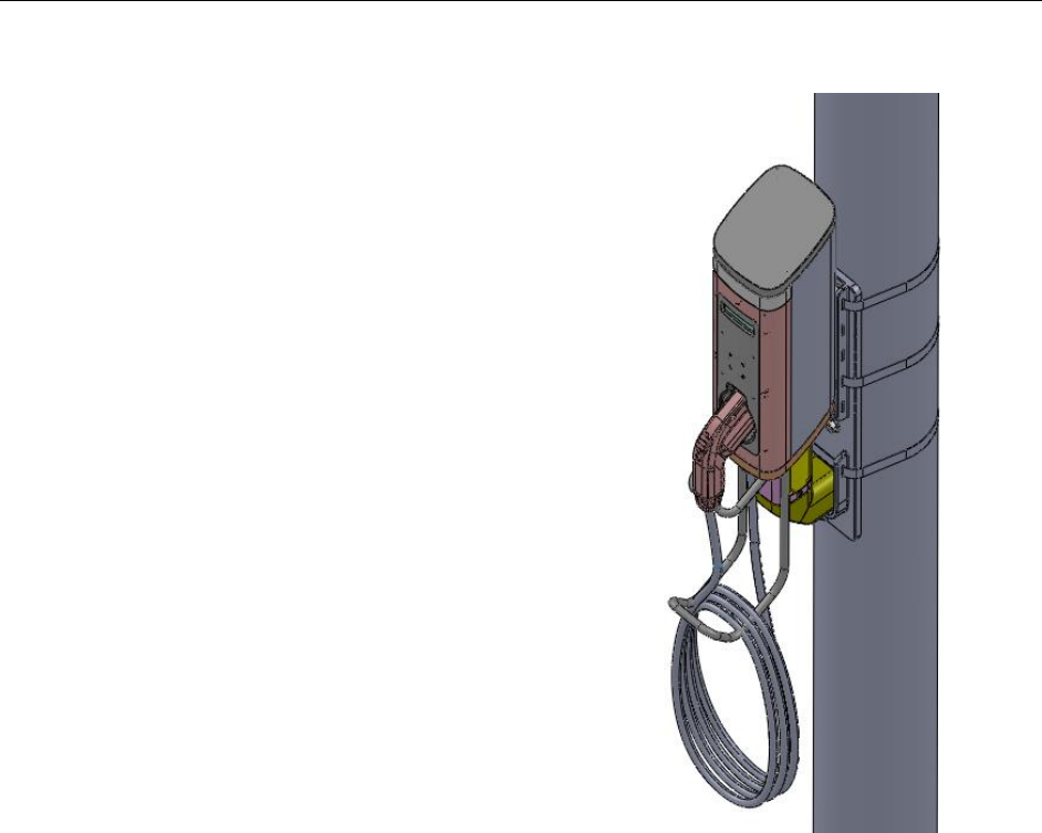
:+&1!S!L!C*,+#%%!+9&!)9#.30*3!:+#+0'*!
Now we are ready to install the charging station.
!
F'G*+!+9&!49#.30*3!,+#+0'*!
Carefully insert the Charging Station Head Unit on top of the
Wall/Pole Mount Bracket Post as shown in the diagram. The
access panel on the Charging Station Head Unit should be
aligned with the panel on the Wall/Pole Mount Bracket Post.
!
U0.D%V!(#,+&*!+9&!49#.30*3!,+#+0'*!
Attach the Charging Station Head Unit to the Post using the
four (4) tamper-resistant screws provided (two on each side).
Ensure the charging station is plumb using a Level. Check that
the Head Unit is now securely fastened to the Post.
Access
Panel
Access
Panel
Tamper-
resistant
Screws
39 | Page
)'**&4+0*3!+9&!I0.&,!
Open the Access Panel by removing the four (4) screws. Locate and access the wires inside.
Carefully pull these wires a few inches outside of the access panel, to reveal 3 wires coming
from the Charging Station Head Unit (for Level-2 charging stations the color codes are Red,
Black and Green) and 3 wires from the Pedestal with the same color combination. Remove the
insulation on each wire and prepare to connect those using wire-nuts.
Match the wires using the colors (Black-Black, Green-Green & Red-Red) and connect them
using wire nuts as illustrated above. Once connected, slowly insert the wires into the device and
replace the access panel cover using the screws previously removed.
Caution: Refer to the wire color codes (Page 8) and strictly adhere to this convention while
connecting the charging station and electrical supply wires. Incorrect wiring can lead to an
electrical hazard.
Charging Station Installation Guide
-'I&.!O1!
Congratulations!
You have now finished the installation of the pole-mounted
ChargePro™ 620 Charging Station!
You can now power up the device.
41 | Page
ME!M11&*50K!
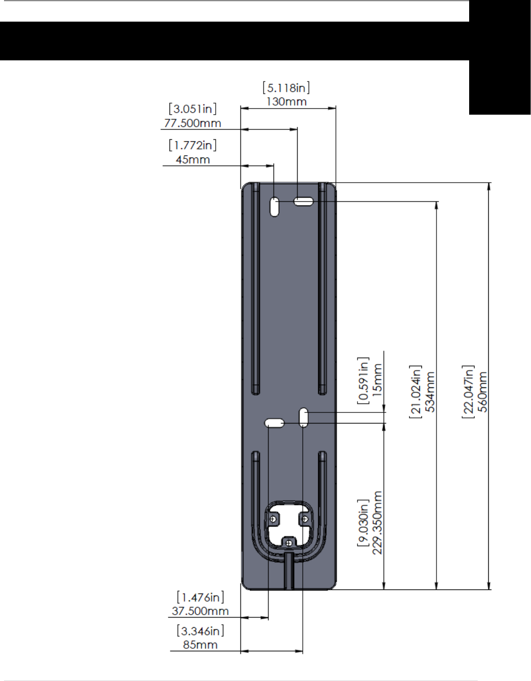
2#%%!F'G*+!X.#4J&+!Y0D&*,0'*!
A
Charging Station Installation Guide
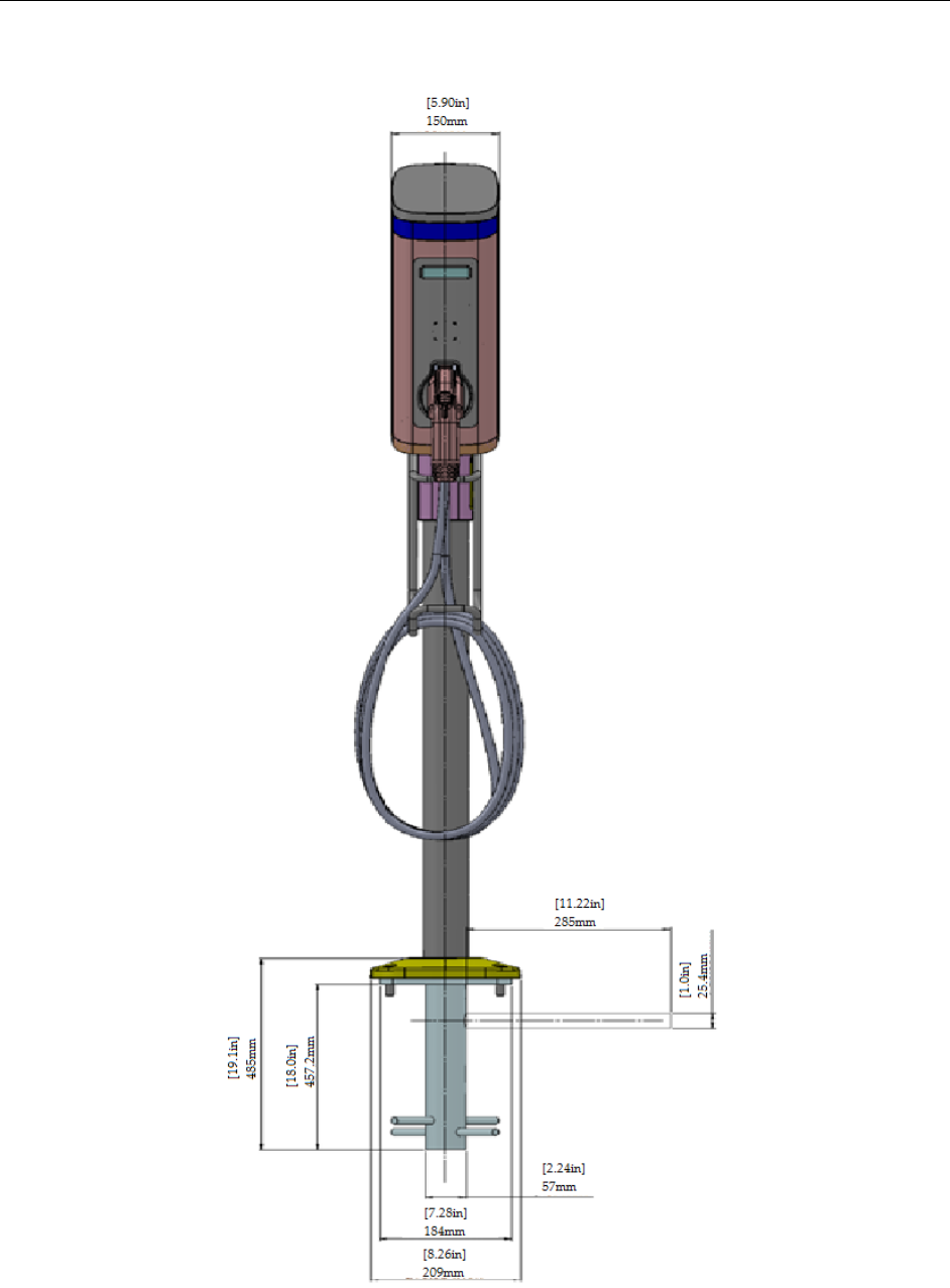
-&5&,+#%!D'G*+!50D&*,0'*,!;U.'*+/70&I?!
*Approximated Values
43 | Page
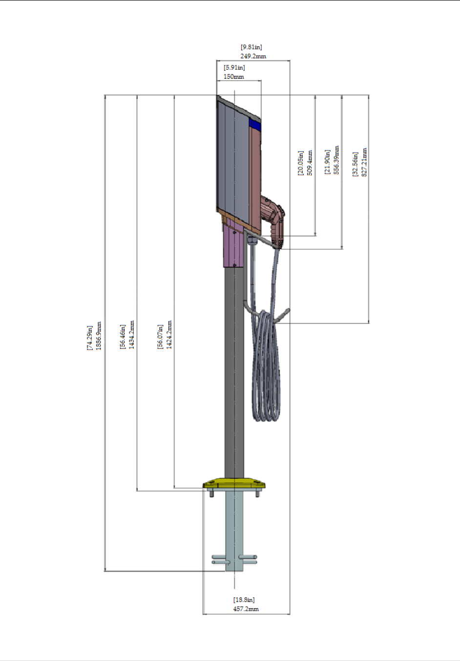
X'%%#.5!D'G*+!50D&*,0'*,!;:05&/70&I?!
*Approximated Values

Charging Station Installation Guide
IMPORTANT INSTRUCTIONS FOR MAINTAINING ENVIRONMENTAL INTEGRITY
!
Maintenance of the device
The device does not need any regular maintenance and there are no customer serviceable parts inside. Any maintenance of the
device needs to be done by a qualified manufacturer authorized service professional. When maintenance needs to be done please
adhere to the following instructions.
- Turn off the power to the device.
- Open the access panel and disconnect all wires. For more explanation on access panel read chapter 2 or 3.
- Remove the screws used to mount the charger device on the Pedastal or Wall mount.
- Lift up the device and take it to an indoor facility, where you can proceed to open the bottom screws for maintenance.
- DO NOT open up the device out-doors, exposing the inner circuits to environmental hazard.
!
Cleaning the device
The device may be cleaned from time to time by following the instructions below:
- Use clean soft cloth along with mild detergent to wash the dirt off the device.
- Do not use high pressure water on the device to wash it. You may pour water gently from the top and use a wet/dry cloth
to clean all the sides.
- Never use strong detergents or any other chemicals (Acids, petrol, thinner or any other solvent) on the device.
- Do not exert too much of pressure on the device while cleaning it.
- There is no need to open the device for cleaning up, so do not remove any of the screws.
- Do not use vacuum cleaners to clean the device.