SENA TECHNOLOGIES PARANI10 Bluetooth Serial Adaptor User Manual manual parani10 v1 0 0
Sena Technologies,Inc. Bluetooth Serial Adaptor manual parani10 v1 0 0
Users Manual
1
Parani10
Enabling Wireless Serial Communication
Users Guide
Version 1.0.0
2005-03-07
2
Copyright Information
Copyright 1998-2004, Sena Technologies, Inc. All rights reserved.
Sena Technologies reserves the right to make any changes and improvements to its product
without providing prior notice.
THIS DEVICE COMPLIES WITH PART 15 OF THE FCC RULES.
Operation is subject to the following two conditions;
(1) this device may not cause harmful interference, and
(2) this device must accept any interference received, including interference that may cause
undesired operation.
CAUTION: Changes or modifications not expressly approved by the party responsible for
compliance could void the user’s authority to operate the equipment.
Trademark Information
Parani™. is a trademark of Sena Technologies, Inc.
Windows® is a registered trademark of Microsoft Corporation.
Ethernet® is a registered trademark of XEROX Corporation.
Notice to Users
Proper back-up systems and necessary safety devices should be utilized to protect against
injury, death or property damage due to system failure. Such protection is the responsibility of
the user.
This device is not approved for use as a life-support or medical system.
Any changes or modifications made to this device without the explicit approval or consent of
Sena Technologies will void Sena Technologies of any liability or responsibility of injury or loss
caused by any malfunction.
Technical Support
Sena Technologies, Inc.
210 Yangjae-dong, Seocho-gu
Seoul 137-130, Korea
Tel: (+82-2) 573-5422
Fax: (+82-2) 573-7710
E-Mail: support@sena.com
Website: http://www.sena.com

3
Revision History
Revision Date Name Description
V1.0.0 2005-03-02 D.H. Shin Initial Release
4
Table of Contents
1. Introduction ........................................................................................................................ 6
1.1 Overview ................................................................................................................................6
1.2 Package Check List................................................................................................................6
1.3 Product Specification ..............................................................................................................8
2. Getting Started ................................................................................................................... 9
2.1 Lamps....................................................................................................................................9
2.2 RS232 Interface....................................................................................................................10
2.3 Connecting Parani10 to host ................................................................................................. 12
3. Configuration.....................................................................................................................13
3.1 Using Parani10 Manager.......................................................................................................13
3.1.1 Let’s make P01 to be discoverable/connectable 13
3.1.2 Let’s make P02 search and connect to P01 16
3.1.3 Let’s make Auto-Connection between P01 and P02 17
3.2 Using a Terminal Program..................................................................................................... 20
3.2.1 Connecting Parani10 to host 20
3.2.2 Making the first Parani10/Bluetooth connection 20
3.2.3 Making Parani10 do INQUIRY SCAN and PAGE SCAN 21
3.2.4 Releasing the existing Bluetooth connection 22
3.2.5 Automatic connection of two Parani10 Units 23
3.2.6 AT command vs. Operational Status 24
4. For Multi-Serial Connections............................................................................................26
4.1 Parani100.............................................................................................................................26
Appendix A: AT command sets............................................................................................27
AT<cr> 27
ATZ<cr> 27
AT&F<cr> 27
AT+BTINQ?<cr> 27
ATD BD_ADDR <cr> 28
ATD<cr> 28
AT+BTSCAN <cr> 28
AT+BTSCAN, n, to<cr> 29
AT+BTSCAN, BD_ADDR, to<cr> 29
AT+BTCANCEL<cr> 29
5
+++ 30
ATO<cr> 30
ATH<cr> 30
AT+BTSEC, Authentication, Encryption <cr> 30
AT+BTLAST?<cr> 31
AT+BTMODE, n<cr> 31
AT+BTNAME=”FriendlyName”<cr> 31
AT+BTKEY=”nnnn”<cr> 31
AT+BTINFO?<cr> 32
AT+BTLPM,n<cr> 32
AT+BTSD?<cr> 32
AT+BTCSD<cr> 33
AT+BTFP,n<cr> 33
AT+UARTCONFIG, baudrate, parity, stopbit,handshaking<cr> 33
Full AT commands set 33
Appendix B: Power Adaptor Specification...........................................................................39
Appendix C: Troubleshooting ..............................................................................................42
C.1 ON/OFF of Hardware Flow Control ....................................................................................... 42
C.2 Enabling/Disabling of Response Signals OK, CONNECT & ERROR......................................43
C.3 For DCE connection.............................................................................................................44
C.4 Hardware Reset ................................................................................................................... 44
C.5 How to get Bluetooth CF cards connected to Parani10 .......................................................... 44
6
1. Introduction
1.1 Overview
Parani10 is a wireless serial adapter based on Bluetooth technology. It enables the RS232
serial devices to communicate wirelessly throughout the range of 200m ~ 1.2km. It supports
both point-to-point connections and point-to-multipoint connections.
Users may configure the Parani10 by using an easy-to-use Windows-based utility software or
by using a standard AT command set.
Parani10 allows users to choose various power supply options, i.e. Power by DC power cable,
Power by external DC-adapter, Power by USB power cable, Power by pin 9 of DB9 connector.
Typical application areas of the Parani10 include:
• RS232 cable replacement
• Truck/Bus monitoring system
• Car Diagnostics
• Wireless POS system
• Wireless Factory monitoring
• PLC programming
• Wireless machine (healthcare/industrial) monitoring
• Wireless Printing
• Wireless logistics
1.2 Package Check List
- DC Power cable
- Dipole antenna
- CD-ROM, including the Parani10_Manager software and manual.
7
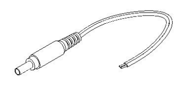
Fig. 1.2.1 DC Power Cable
*Red colored wire of DC power cable is for ‘+’

8
1.3 Product Specification
Serial Interface:
RS232, Female DB9, 1200~230 Kbps
Automatic detection of hardware flow control
DTR/DSR for loop-back & full transfer
Bluetooth Interface:
Bluetooth v1.1
Class I
Protocols – RFCOMM, L2CAP, SDP
Profiles - General Access Profile, Serial Port Profile
Working distance
Default Antenna - Default Antenna up to 200m
Patch Antenna - Default Antenna up to 400m
Patch Antenna - Patch Antenna up to 1200m
Configuration:
Windows Utility, Parani10 Manager
Modem AT command set
Diagnostic LED:
Status and Power LED
Power:
4V~12V, minimum 150mA
Nominal power consumption of 40mA@9600bps and 72mA@115Kbps speed
Power supply options
Power via a standard AC-plug DC-adapter
Power via USB power cable
Power via DC power cable
Power via pin 9 of DB9 connector

9
Environmental:
Operating temperature: 5? to 50?
Storage temperature: -4? to 66?
Humidity: 90% Non-condensing
Physical properties:
Dimension (L x W x H) 96 x 31 x 16 (mm), 3.8 x 1.2 x 0.6 (in.)
Weight 14g
Approvals:
Bluetooth 1.1
FCC(A), CE, TELEC
Warranty:
5-year Limited Warranty
2. Getting Started
2.1 LED Indicators
The Parani10 STATUS LED indicates the following:
Lamps Description
Amber Standard mode on Parani10 power-up
Solid Green Connected to another Bluetooth device
Green Flashing
At 1 sec interval INQUIRY operation
STATUS
Green Flashing
At 3 sec interval INQUIRY SCAN or PAGE SCAN operation
POWER Green Power is being supplied
10
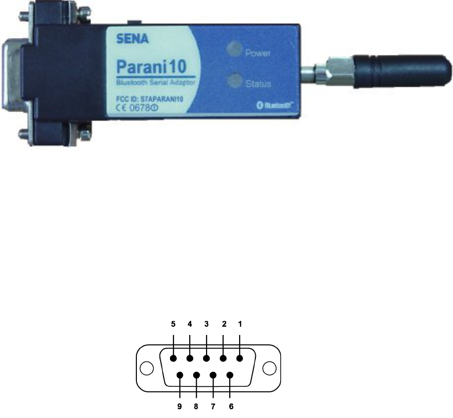
Figure 2.1.1 Parani10
2.2 RS232 Interface
Parani10 has a DB-9 (female) connector as shown below in Fig 2.2.1
Figure 2.2.1. DB-9 (Female)
• The serial interface is RS232 DCE configured; a DTE device can be connected.
• Baud rate: 1200~230400bps
• Hardware flow control (RTS/CTS)

11
Pin Signal Direction
1 CD Output
2 TxD Output
3 RxD Input
4 DSR Input
5 GND -
6 DTR Output
7 CTS Input
8 RTS Output
9 Vcc Input
Table 2.2.1. Parani10 DB-9 Specification
Parani10 is designed to operate as DCE (Data Communications Equipment).
To connect to DTE (Data Terminal Equipment), for example a PC or a laptop, a straight cable
must be used as in below.
CD, 1 CD, 1
TxD,
2
RxD, 2
RxD,
3
TxD, 3
DSR,
4
DTR, 4
GND,
5
GND, 5
DTR,
6
DSR, 6
CTS,
7
RTS, 7
Parani10 (DCE)
RTS,
8
CTS, 8
Host System (DTE)

12
*DTR/DSR of Parani10 will function for either a Loop-back operation or for full transfer. Users
may select a function of DTR/DSR using AT command- ATS14. Default value of ATS14 is 1.
• ATS14=1<cr>: Default setting. Users may use DTR/DSR lines for communications
• ATS14=0<cr>: Users may use DTR/DSR lines for Loop-back only.
• ATS14? : To see current status of ATS14.
*Default setting of CD line in Parani10 is to show the status of Bluetooth connection. If users
want to use CD line to send CDC signal to the other side, such as for a connection between
Parani10 and DCE device, users need to configure ATS13.
• ATS13=0<cr>: Default setting. Users may use CDC line for checking a Bluetooth connection.
• ATS13=1<cr>: Users may receive CDC signal from other Parani10.
(This function will be available from future version of Parani10 for DCE devices)
• ATS13 ?: To see current status of ATS13.
2.3 Connecting Parani10 to host
Step 1. Connect a Parani10 to a serial port of the host computer.
Step 2. Supply power by using one of the following methods:
Power via DC power cable
Power via a standard AC-plug DC-adapter (Option)
Power via USB power cable (Option)
Step 3. Turn on the Parani10 power by using the switch on the side.
Step 4. Check the LED lamps.
The Power LED must display a solid green color, to indicate that power is being supplied
properly.
Step 5. Proceed with the steps for the configuration to make Parani10 work.
See Chapter 3. Configuration for details.
13
3. Configuration
3.1 Using Parani10 Manager
With Parani10, Bluetooth wireless connections can be made to any Bluetooth device
supporting SPP (Serial Port Profile). Especially when using the Parani10 as a cable
replacement, take advantage of the Parani10 automatic connection feature. Once a pair of
Parani10’s is set for this feature, they automatically connect whenever powered up. A pair of
Parani10 units, within their radio range, may be used as a virtual RS-232 cable.
To allow wireless connections between two Bluetooth devices, one device should be in
Discoverable (INQUIRY SCAN) and Connectable (PAGE SCAN). Most Bluetooth devices are
set to Discoverable and Connectable by the manufacture. However, to allow Parani10 to
respond to the INQUIRY and PAGE operations of other Bluetooth devices, INQUIRY SCAN and
PAGE SCAN modes will need to be activated.
Before making the first Bluetooth connection with Parani10 units, be prepared with a pair of
Parani10 units and also install the Parani10_Manager program on the CD enclosed in the
Parani10 product package.
*Configuration By Parani10_Manager
Please prepare two of the Parani10s to make connection.
Let’s say 1st unit as ‘P01’ and 2nd unit as ‘P02’ in this guide book. Make sure that power to both
P01 and P02 are ALWAYS supplied, even when you detach from your computer.
3.1.1 Let’s make P01 to be discoverable/connectable.
In this procedure, P01 will become discoverable/connectable to be able to receive connection
from P02.
1-1. Attach P01 to your PC, and start Parani10_Manager
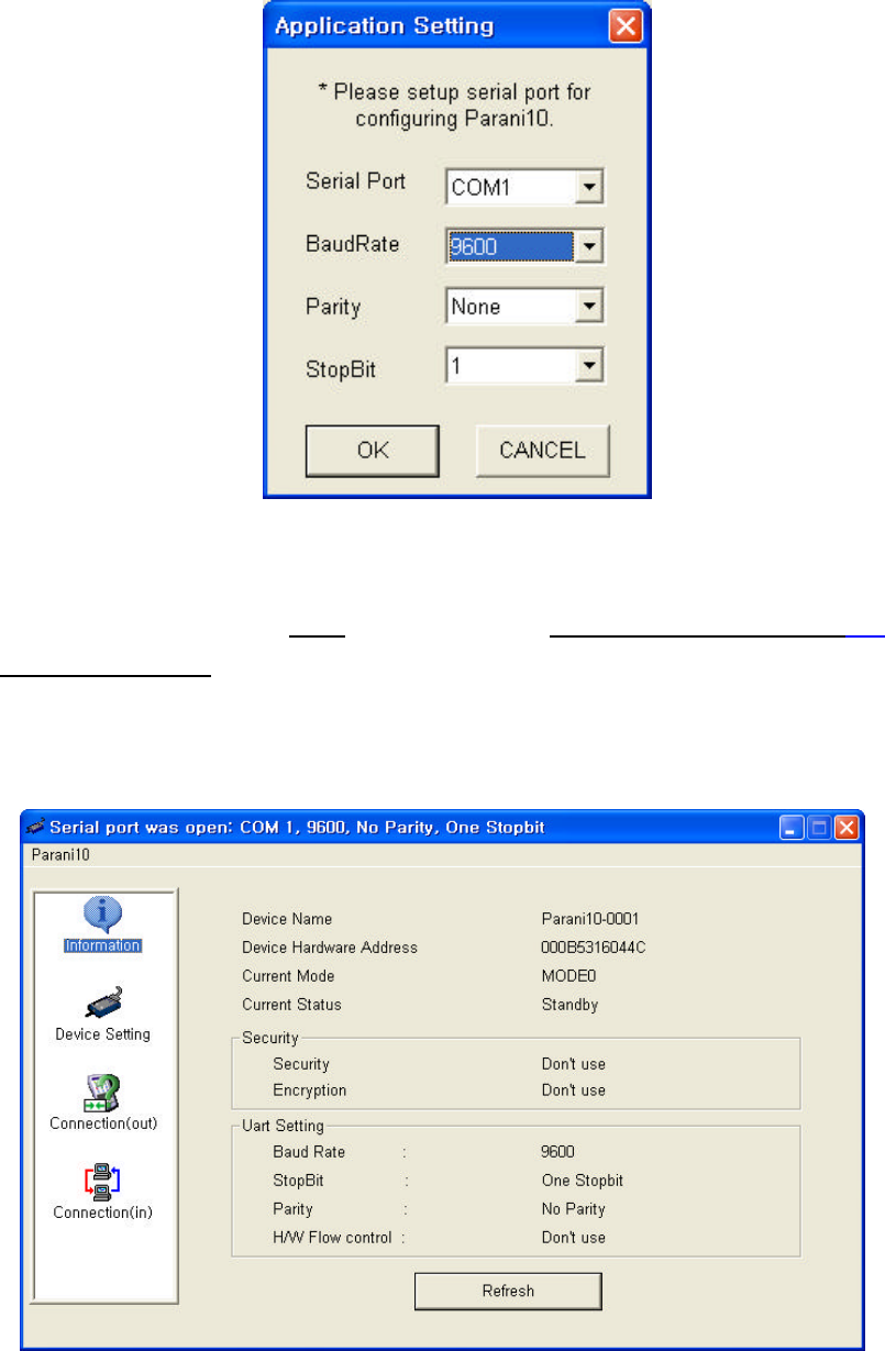
1-2. Start Parani10_Manager then you will see a pop-up window for configuration of
Parani10_Manager.
14
<Fig. 3.1.1>
1-3. Select the number of the Serial port where P01 is attached as in the Fig. 3.1.1 above.
1-4. Users need to select exactly same Baud/Parity/StopBit as real settings of attached P01.
9600/No/OneStopBit are default initial settings of all of Parani10s.
1-5. Press OK button when finished.
1-6. Open ‘Parani10_Manager->Start Configuration’ on the upper left menu.
Parani10_Manager will bring the information on the attached P01 as in Fig. 3.1.2
<Fig. 3.1.2>
15
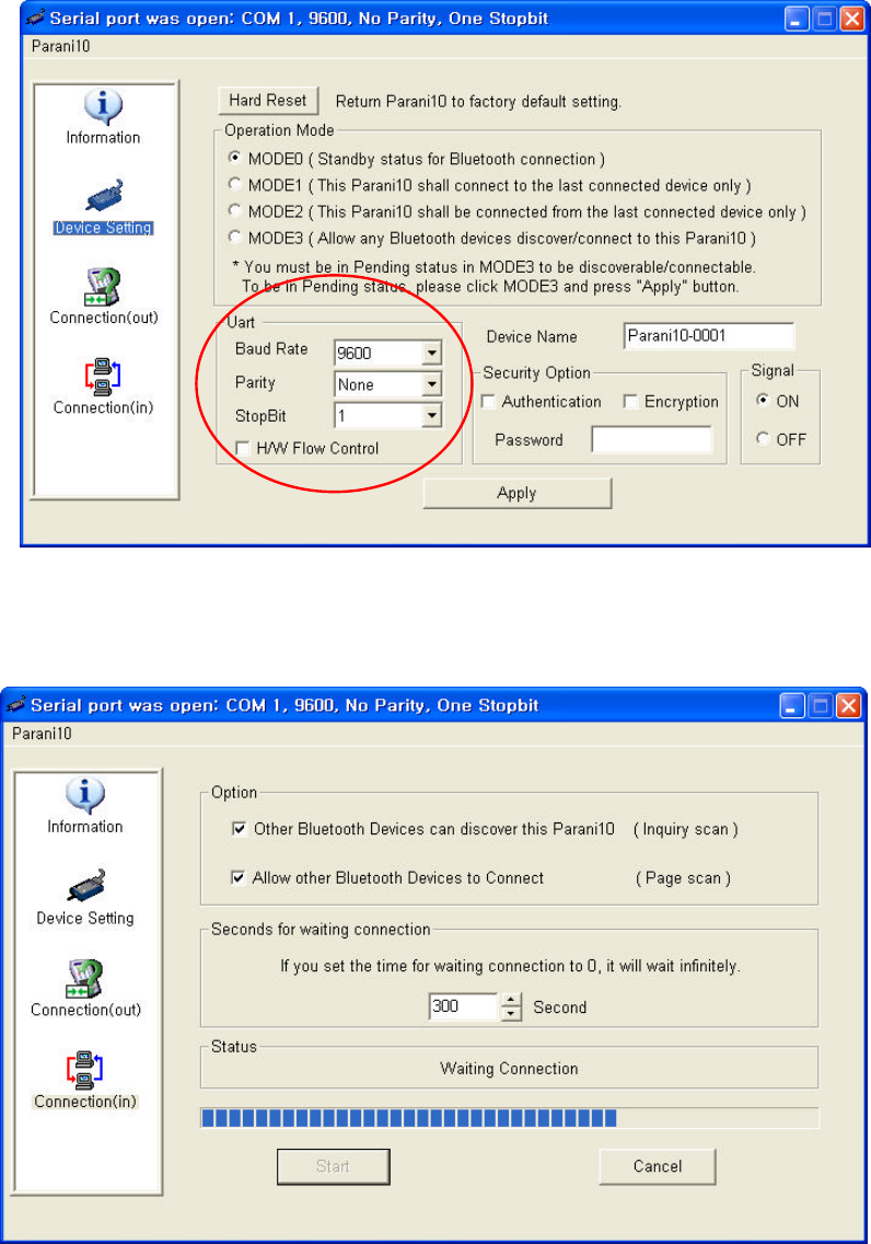
1-7. Click the ‘Device Setting’ icon in the list control box. Users may change the Baud
rate/Parity/StopBit to meet their individual needs.
<Fig. 3.1.3>
1-8. Click the ‘Connection(in)’ icon in list control box. Check both options and then click the
START button as shown in Fig. 3.1.4.
<Fig. 3.1.4>
16
1-9. P01 now became ‘Discoverable/Connectable’ so it can receive Bluetooth connection from
P02. The STATUS LED of P01 will blink green, twice every 3 seconds.
1-10. Detach P01 from your computer, making sure its status LED is blinking green.
1-11. Close Parani10_Manager.
3.1.2 Let’s make P02 search and connect to P01.
2-1. Attach P02 to your PC, and start Parani10_Manager.
2-2. Select the number of the Serial port where P02.
2-3. Users need to select exactly same Baud/Parity/StopBit as the setting of attached P02.
9600/No/OneStopBit is default setting of all of Parani10s.
2-4. Press OK button.
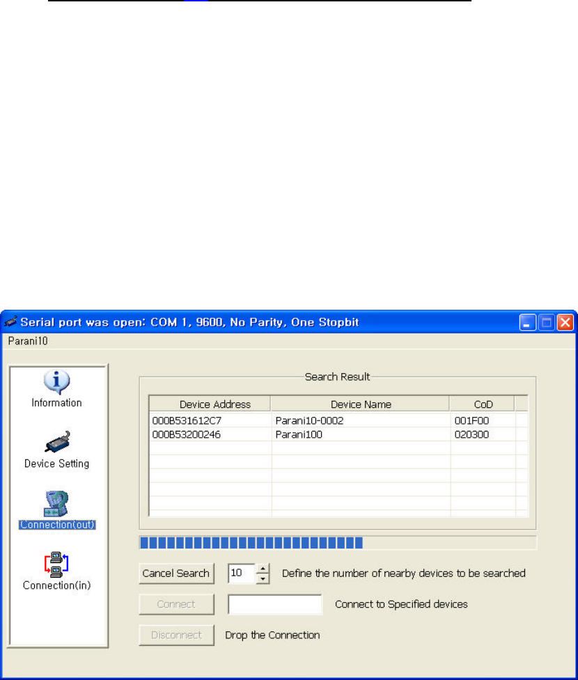
2-5. Select the ‘Connection(out)’ icon in the list control box and click the SEARCH button.
<Fig. 3.1.5>
2-6. Search P01 from the searched list. Device Address of P01 can be found on the back side of
P01. If you find P01, press Cancel button to finish searching.
Make sure that Status LED of P01 is still blinking in Green.
2-7. Please select P01 from the searched list, then press CONNECT TO button.
17
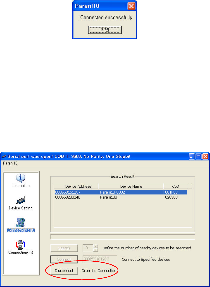
2-8. You will get Successful Connection message.
<Fig. 3.1.6>
2-9. Now, Status LEDs on Both P01 and P02 are Green, which means they are connected.
2-10. Do not detach P02 from your computer yet, we will go to next stage for Auto-connection
(Always-connection).
3.1.3 Let’s make Auto-Connection between P01 and P02
3-1. With P02 which is still attached to your computer, in Connection(out) page,
press the DISCONNECT button at the bottom to release the connection for a while.
P02 will remember the last-connected device, even after disconnection.
<Fig. 3.1.7>
18
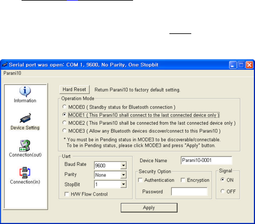
3-2. Now, Status LEDs of P02 becomes ‘Orange’, as well as P01, as they are disconnected.
3-3. Select Device Setting icon in the list control box, and select MODE1 in Operation Mode and
apply.
<Fig. 3.1.8>
3-4. Now jobs for P02 are finished. Detach P02 from your computer.
3-5. Attach P01 to your computer.
3-6.Restart Parani10_Manager.
19
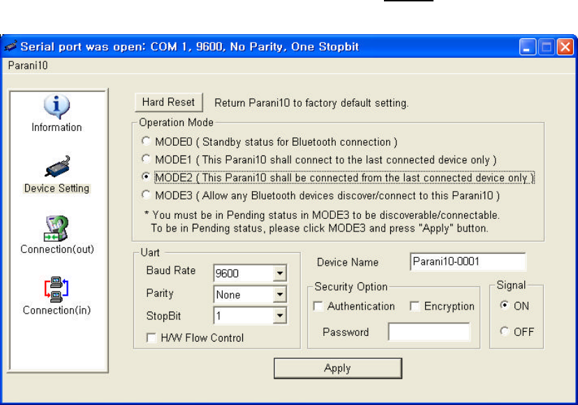
3-7.Select Device Setting icon in the list control box, and select MODE2 in Operation Mode and
apply.
<Fig. 3.1.9>
3-8. Now, detach P01 from your computer.
3-9. Make sure that power to Both P01 and P02 are supplied.
With both, P01 and P02, turn off both units using the Switch located on the side of its body.
Then, turn on both P01 and P02 almost at the same time.
Now, you will see Green Status LEDs on both units.
P01 and P02 will be connected automatically, as long as the configuration for both units remains
unchanged.
20
3.2 Using a Terminal Program
Parani10 units are easily controlled and configured via Parani10_Manager. Likewise, AT
command sets are supported by Parani10 to allow device control capabilities used by the
terminal program of your choice.
3.2.1 Connecting Parani10 to host
For Parani10 use, follow the simple instructions below:
1. Connect a Parani10 to a host serial port. Then, turn on the Parani10.
2. Check the STATUS LED color. Amber indicates standard mode.
3. Execute any terminal program and activate Local Echo.
4. Configure the host serial port to match the Parani10 unit configuration. The
Parani10 default configuration is 9600 bps Baud, 8 Data bit, No Parity, 1
Stop bit and H/W flow control.
5. Enter ‘AT’ command at the prompt. A Parani10 ‘OK’ reply indicates proper
operation.
3.2.2 Making the first Parani10/Bluetooth connection
As stated before, Bluetooth wireless connections can be made with any
other Bluetooth device supporting Bluetooth SPP (Serial Port Profile).
For Bluetooth wireless connections to a Parani10, first make another
Parani10 ‘Discoverable’ and ‘Connectable’. In this case, refer to
section 3.2.3 before following the instructions below.
1. First check the status of the Parani10 by entering ‘AT+BTINFO?’. The
Parani10 response is comprised of BD_ADDR, Device Name, Operating
Mode, Operating Status, Authentication and Encryption flags. To make a
connection to other Bluetooth devices, the operating status of the first
Parani10 should be ‘STANDBY’. A ‘PENDING’ operating status of the first
Parani10 indicates the unit is busy with another operation. In this case,
cancel the ongoing operation by entering the ‘AT+BTCANCEL’ command.

21
2. Search other local Bluetooth devices by entering the ‘AT+BTINQ?’ command.
3. Check the search list. Enter ‘ATD’ command in the BD_ADDR of any
Bluetooth device for connection. During the connection process, the
STATUS LED will flash green every second.
4. The Parani10 returning a ‘CONNECT’ message and displaying a green
STATUS LED indicates connection.
3.2.3 Making Parani10 do INQUIRY SCAN and PAGE SCAN
To make the Parani10 “Discoverable” (INQUIRY SCAN) and “Connectable”
(PAGE SCAN), these operations must be manually activated.
1. Check the Parani10 status by entering an ‘AT+BTINFO?’ command.
ATD000B53000080
OK
CONNECT
AT+BTINQ?
000B53000080, Parani10-000080,001F00
0004B300E205,AP2002:1 #0,020300
OK
AT+BTINFO?
000B530000A9, Parani10-0000A9,MODE0,STANDBY,0,0
OK

22
2. Enter the ‘AT+BTSCAN’ command. The Parani10 will start INQURY SCAN
and PAGE SCAN operation. During the process, the Parani10 will flash
twice every 3 seconds until it is connected to another Bluetooth device.
3. Try Bluetooth connection to the Parani10 from the other Bluetooth device.
Once connected the first Parani10 will return the ‘CONNECT’ message and
the STATUS LED will display a continuous green without flashing.
3.2.4 Releasing the existing Bluetooth connection
Once connected successfully, the Parani10 becomes transparent to any serial
applications on hosts. Data may be transferred within the radio range of the
Parani10. According to Parani10 terminology, this operating status is called
‘ONLINE STATUS’. In ONLINE STATUS, all AT commands are treated as
characters and are ignored by the command interpreter of the Parani10.
Therefore to escape from ONLINE STATUS enters escape string ‘+++’.
AT+BTSCAN
OK
CONNECT
AT+BTSCAN
OK
AT+BTINFO?
000B530000A9,PARANI10-0000A9,MODE0,STANDBY,0,0
OK

23
1. Transition from ONLINE STATUS to STANDBY STATUS by entering ‘+++’
string to the Parani10. Check the current Parani10 status by entering the
‘AT+BTINFO?’ command. The Parani10 status should display CONNECT
STATUS.
2. Release the current Bluetooth connection by entering ‘ATH’ command. Once
disconnected successfully, the Parani10 returns the ‘DISCONNECT’ message.
3.2.5 Automatic connection of two Parani10 Units
Two Parani10 units connect automatically when powered up. For automatic
Parani10 connection first make a Bluetooth connection between two Parani10
units. Once connected, the Parani10 stores the 48-bit BD_ADDR of its
counterpart. To expedite 48-bit BD_ADDR input operation, the Parani10 is
designed to store the BD_ADDR of its latest counterpart.
1. Set one Parani10 to do INQUIRY SCAN and PAGE SCAN operation as
directed in section 3.2.3.
2. Set the other Parani10 to connect to the Parani10 in the previous step.
3. Once connected successfully, both Parani10 units store the BD_ADDR of
ATH
OK
DISCONNECT
+++
OK
AT+BTINFO?
000B530000A9, Parani10-0000A9,MODE0,CONNECT,0,0
OK

24
their counterpart in their internal Flash. When desired, release the
connection as directed in section 3.2.4.
4. Set the operating mode of one Parani10 to MODE 1 by entering an ‘AT+
BTMODE’ command as shown below.
5. Set the operating mode of the other Parani10 to MODE 2 by entering an
‘AT+BTMODE’ command as show below.
6. Turn both Parani10 units power off. The Parani10 pair will connect
automatically when they are powered up again.
7. To release this paring, set them to MODE 0 by entering ‘AT+BTMODE, 0’. or
reset the units by pressing the RESET button.
3.2.6 AT command vs. Operational Status
The AT command sets listed above can be executed per Parani10 operational status. The
following table shows the operational status and executable AT command sets.
AT+BTMODE,0
OK
AT+BTCANCEL
OK
AT+BTMODE,2
OK
AT+BTMODE,1
OK

25
AT Command Standby Pending Online
AT<cr> v v
ATZ<cr> v v
AT+BTINQ?<cr> v1)
ATD112233445566<cr> v1)
ATD<cr> v1)
AT+BTSCAN,n<cr> v1)
AT+BTSCAN,112233445566<cr>
v1)
AT+BTCANCEL<cr> v
+++ v
ATO<cr> v2)
ATH<cr> v2)
AT+BTAUTH,Auth,Encr<cr> v3)
AT+BTMODE,n<cr> v3) 4)
AT+BTNAME=”Name”<cr> v3)
AT+BTKEY=”nnnn”<cr> v3)
ATS10=0 or ATS10=1
AT+BTINFO?<cr> v v
AT+UARTCONFIG,b,p,s<cr> v3) 4)
1) Effective when Parani10 is not in connection with Bluetooth.
2) Effective when Parani10 is in connection status with Bluetooth.
3) Recommend to be used when Parani10 is not in connections status with
Bluetooth
4) To apply new values to Parani10, software reset requires by ATZ
command or restart Parani10.

26
4. For Multi-Serial Connections
4.1 Parani100
For multiple wireless serial connections, the Parani100 is recommended as a companion
product of the Parani10, wireless serial adapter. The Parani100 is basically a Bluetooth/IP
gateway which converts the Bluetooth based data stream to data receivable by various devices
in a LAN. It supports 7 Bluetooth connections and equipped with Serial/IPTM COM Port
redirector which enables serial data transfer to IP networks so that users may use existing serial
program to communicate with the serial devices through IP/Bluetooth network.
<Fig. 4.1.1 The Parani100, Bluetooth/IP Gateway>
27
Appendix A: AT command sets
The following AT command sets are supported by PARANI10. Here <cr> represents carriage
return of ASCII Code (0x0D) and <lf> represents line feed of ASCII Code (0x0A).
AT<cr>
Function : Check the presence of your PARANI10.
Response : <cr><lf>OK<cr><lf> or
<cr><lf>ERROR<cr><lf>
Description : In standard mode, you can check whether your PARANI10 is connected to a
host correctly by using this AT command.
ATZ<cr>
Function : Do soft-reset
Response : <cr><lf>OK<cr><lf> or
<cr><lf>ERROR<cr><lf>
Description : You can do soft-reset by using this AT command. When your PARANI10 is
already connected to the other device, it disconnects the connected device.
You can halt the current ongoing operation by using this command.
AT&F<cr>
Function : Restore the default configuration of your PARANI10.
Response : <cr><lf>OK<cr><lf> or
<cr><lf>ERROR<cr><lf>
Description : You can restore the default configuration of your PARANI10 by executing this
AT command.
AT+BTINQ?<cr>
Function : Search (INQUIRY) other Bluetooth devices nearby.
Response : <cr><lf>BD_ADDR, Device Name , Class of Device<cr><lf>
<cr><lf>BD_ADDR, Device Name , Class of Device<cr><lf>
…
<cr><lf>BD_ADDR, Device Name , Class of Device<cr><lf>
<cr><lf>OK<cr><lf>
Description : This command is used to inquiry other Bluetooth devices nearby. The
INQUIRY process is carried out during the predefined time duration (30
28
seconds). The maximum number of INQUIRY result is 10.
ATD BD_ADDR <cr>
Function : Make connection with the given BD_ADDR.
Response : <cr><lf>OK<cr><lf>
<cr><lf>CONNECT<cr><lf>
or
<cr><lf>OK<cr><lf>
<cr><lf>ERROR<cr><lf>.
Description : After getting BD_ADDRs, you can make a connection to another Bluetooth
device by using this AT command. Once you input this command, PARANI10
tries to connect the Bluetooth device with the given BD_ADDR for 5 minutes.
The connection failure happens when a Bluetooth device with the given
BD_ADDR is not in PAGE SCAN mode or is already connected to other
Bluetooth device.
ATD<cr>
Function : Make connection with a Bluetooth device connected most recently.
Response : <cr><lf>OK<cr><lf>
<cr><lf>CONNECT<cr><lf>
or
<cr><lf>OK<cr><lf>
<cr><lf>ERROR<cr><lf>.
Description : If you execute this AT command, your PARANI10 will make a connection with
a Bluetooth device which your PARANI10 connected to most recently. To
make this AT command work successfully, there should be at least one
successful connection to another Bluetooth you want to connect to.
AT+BTSCAN <cr>
Function : Make your PARANI10 do INQUIRY SCAN and PAGE SCAN alternately.
Response : <cr><lf>OK<cr><lf>
<cr><lf>CONNECT<cr><lf>
Description : You can force your PARANI10 to do INQUIRY SCAN or PAGE SCAN
alternately with this AT command. Your PARANI10 does INQUIRY SCAN and
PAGE SCAN until it has a connection from other Bluetooth device. Once
connected, your PARANI10 returns ‘CONNECT’ message. You can use
29
‘AT+BTCANCEL’ to cancel this operation. This AT command has the same
effect of ‘AT+BTSCAN,3,0’.
AT+BTSCAN, n, to<cr>
Function : You can force your PARANI10 to do INQUIRY SCAN or PAGE SCAN.
Response : <cr><lf>OK<cr><lf>
<cr><lf>CONNECT<cr><lf>
or
<cr><lf>OK<cr><lf>
<cr><lf>ERROR<cr><lf>
Description : To make PARANI10 to be Discoverable and Connectable from other
Bluetooth devices, you should set its INQUIRY SCAN and PAGE SCAN. To
make your PARANI10 do INQUIRY SCAN only, you should set n as 1. To
make your PARANI10 do PAGE SCAN only, you should set n as 2. When n is
set to 3, your PARANI10 does INQUIRY SCAN and PAGE SCAN alternately.
Here, ‘to’ indicates the time out interval of INQUIRY SCAN and PAGE SCAN
operations. If you set ‘to’ to ‘0’, your PARANI10 does INQUIRY SCAN and
PAGE SCAN until it has a connection from other Bluetooth device. Your
PARANI10 returns ‘CONNECT’ message when it is connected from other
Bluetooth device within the given time out intervals. Otherwise, it returns
‘ERROR’ message.
AT+BTSCAN, BD_ADDR, to<cr>
Function : Wait Bluetooth connection from a device with given BD_ADDR.
Response : <cr><lf>OK<cr><lf>
<cr><lf>CONNECT<cr><lf>
or
<cr><lf>OK<cr><lf>
<cr><lf>ERROR<cr><lf>
Description : Once you enter this AT command, your PARANI10 does PAGE SCAN.
However, it waits a connection from a Bluetooth device with the given
BD_ADDR. This process lasts during ‘to’ time interval. Especially when ‘to’
has value of ‘0’, your PARANI10 waits connection infinitely.
AT+BTCANCEL<cr>
Function : Cancel currently ongoing operation of your PARANI10.
30
Response : <cr><lf>OK <cr><lf>
Description : This AT command works only when your PARANI10 is busy in doing
‘AT+BTSCAN’, ‘ATD’ or ‘AT+BTINQ?’. Once canceled successfully, your
PARANI10 will become STANBY STATUS’.
+++
Function : Make transition from ONLINE STATUS to STANDBY STATUS.
Response : <cr><lf>OK <cr><lf>.
Description : If you input ‘+++’ string to your PARANI10 in ONLINE STATUS, your
PARANI10 goes into STANBY STATUS. Once PARANI10 enters into
STANDBY STATUS, you can use any AT command sets supported by
PARANI10.
ATO<cr>
Function : Make transition from STANBY STATUS to ONLINE STATUS.
Response : None
Description : This AT command is the counter operation of ‘+++”. You can change the
operating status to ONLINE STATUS again by using this command. In
ONLINE STATUS, the data can be transferred between two hosts. The
existence of your PARANI10 becomes transparent to any host applications
which use serial ports.
ATH<cr>
Function : Release the current Bluetooth connection.
Response : <cr><lf>OK<cr><lf>
<cr><lf>DISCONNECT <cr><lf>.
Description : This AT command can be used for disconnecting the existing Bluetooth
connection.
AT+BTSEC, Authentication, Encryption <cr>
Function : Set Bluetooth authentication or encryption features selectively.
Response : <cr><lf>OK<cr><lf>.
Description : By using this AT command, you can set authentication or encryption feature of
your PARANI10 during Bluetooth connection process. Once you set
authentication or encryption features, your PARANI10 stores its status. To
release authentication or encryption features you set, you should use this AT
31
commands or do soft-reset. To enable authentication or encryption, set
authentication or encryption parameter as 1. Otherwise set either of them as 0.
AT+BTLAST?<cr>
Function : Return BD_ADDR of the Bluetooth device to your host which your PARANI10
is connected most recently.
Response : <cr><lf>BD_ADDR<cr><lf>
<cr><lf>OK< cr><lf>
Description : You can use this AT command if you need to refer the BD_ADDR of most
recently connected Bluetooth device.
AT+BTMODE, n<cr>
Function : Set the operating mode of your PARANI10.
Response : <cr><lf>OK<cr><lf>
Description : Your PARANI10 has 4 different operating mode. According to the current
operating mode you set, your PARANI10 behavior differently.
n=0 : This means your PARANI10 is in MODE 0. MODE 0 is the default
configuration.
n=1 : In MODE 1, your PARANI10 will try to make connection to most recently
connected Bluetooth device.
n=2 : In MODE 2, your PARANI10 will wait connection from most recently
connected Bluetooth device.
n=3 : IN MODE 3, your PARANI10 does INQUIRY SCAN and PAGE SCAN
alternately.
AT+BTNAME=”FriendlyName”<cr>
Function : Assign user friendly device name to your PARANI10.
Response : <cr><lf>OK<cr><lf>
Description : You can assign your PARANI10 user friendly name by using this AT command.
With the assigned name, you can distinguish your PARANI10 easily from
other Bluetooth devices. Up to 32 characters are permitted as user friendly
name.
AT+BTKEY=”nnnn”<cr>
Function : Change the passkey.
Response : <cr><lf>OK<cr><lf>
32
Description : When the authentication is enabled in your PARANI10, you should assign
passkey. Two Bluetooth devices which are to be connected should have the
same passkey. The default passkey of your PARANI10 is ‘1234’. You can
assign maximum 16 alphanumeric characters as a passkey.
AT+BTINFO?<cr>
Function : Return the internal status of your PARANI10.
Response : <cr><lf>BD_ADDR,Name,Mode,Status,Auth,Encryp<cr><lf>
<cr><lf>OK<cr><lf>
Description : When you enter this AT commands at a host terminal, your PARANI10 returns
its device information and status to a host. It encompasses BD_ADDR, user
friendly name, operating mode, operating status and authentication/encryption
status. Especially when the operating status is PENDING, it means your
PARANI10 is busy in processing ‘AT+BTINQ?’, ‘ATD’ or ‘AT_BTSCAN’. When
Authentication or Encryption feature is activated, the corresponding
parameter has value of ‘1’.
AT+BTLPM,n<cr>
Function : Set Bluetooth Low power consumption mode.
Response : <cr><lf>OK<cr><lf>
Description : To minimize power consumption, your PARANI10 supports Bluetooth PARK
mode. When you set n as 1, your PARANI10 uses PARK mode. Using PARK
mode might cause extra data transmission delay in some cases.
AT+BTSD?<cr>
Function : Return the list of secured devices.
Response : <cr><lf>BD_ADDR<cr><lf>
<cr><lf>BD_ADDR<cr><lf>
…
<cr><lf>BD_ADDR<cr><lf>
<cr><lf>OK<cr><lf>
Description : Your PARANI10 can pair up to 5 Bluetooth devices. Upon receiving this AT
command, your PARANI10 returns all the BD_ADDRs of the previously paired
Bluetooth devices.

33
AT+BTCSD<cr>
Function : Delete the info of all the paired devices stored in your PARANI10.
Response : <cr><lf>OK<cr><lf>
Description : This AT command just deletes the info of paired devices stored on
PARANI10’s Flash memory. To delete the same info resides on PARANI10’s
RAM, you have to do software reset or hardware reset.
AT+BTFP,n<cr>
Function : Force your PARANI10 to generate passkey automatically.
Response : <cr><lf>OK<cr><lf>
Description : Once paired, your PARANI10 uses the stored link key. By using this AT
command, you can make Bluetooth connection with a new link key. When n is
set to 1, your PARANI10 newly generates a link key during connection
process.
AT+UARTCONFIG, baudrate, parity, stopbit,handshaking<cr>
Function : Configure the serial port of your PARANI10.
Response : <cr><lf>OK<cr><lf>
Description : By using this AT command, you can reconfigure the serial port of your
PARANI10. You can set baudrate, parity, stopbit . To make this command
result active, you should do soft-reset or turn off/on your PARANI10. The
following values are permitted for each parameter.
• Baudrate = 1200, 2400, 9600, 19200, 38400, 57600 or 115200.
230400 (only for Parani10102/202/ESD)
• Parity = N (No parity), E (Even parity) or O (Odd parity).
• Stopbit = 1 or 2.
• Handshaking = 1 or 0
(If ‘1’, hardware handshaking will be used. If ‘0’, handshaking function of
Parani10 will be turned off)
Full AT commands set
No.
Command Response Comments
1) AT<cr> <cr><lf>OK<cr><lf>
2) ATZ<cr> <cr><lf>OK<cr><lf> Drops all connections, disable Inquiry
and Page scans. Reset the Bluetooth

34
module.
3) AT&F<cr> <cr><lf>OK<cr><lf> Reset to factory default state
4)
AT+BTINQ?<cr> <cr><lf>112233445
5,FriendlyName,Co
D<cr><lf>
<cr><lf>112233445
5,FriendlyName,Co
D<cr><lf>
<cr><lf>112233445
5,FriendlyName,Co
D<cr><lf>
<cr><lf>OK<cr><lf>
Inquiry nearby devices. The OK at
the end means end of inquiry.
5)
ATD112233445566<cr> <cr><lf>OK<cr><lf>
<cr><lf>CONNECT
<cr><lf> or
<cr><lf>ERROR<cr
><lf>
Connect to the specified device.
If you want to enable Authentication
and Encryption, just set variable as 1.
6)
ATD<cr> <cr><lf>OK<cr><lf>
<cr><lf>CONNECT
<cr><lf> or
<cr><lf>ERROR<cr
><lf>
Connect to the device that last
successfully connected.
7) AT+BTSCAN<cr> <cr><lf>OK<cr><lf> Enable inquiry and page scans with
timeout of infinity.
8)
AT+BTSCAN,n,to<cr> <cr><lf>OK<cr><lf> Enable inquiry or Page scans.
If n=1, disable page and enable
inquiry.
If n=2, enable page and disable
inquiry.
If n=3, enable both page and inquiry.
Scan will be performed during <to>
seconds.
9) AT+BTSCAN112233445566,to<cr> <cr><lf>OK<cr><lf> Will scan of only specified device.
10) AT+BTCANCEL<cr> <cr><lf>OK<cr><lf> cancel the current pending operation
when the device is inquiring, paging

35
or scanning mode.
11) +++ <cr><lf>OK<cr><lf> Drop from online mode to command
mode.
12) ATO<cr> <cr><lf>OK<cr><lf> Return to online mode if currently
being connected.
13) ATH<cr> <cr><lf>OK<cr><lf> Drop the connection.
14) AT+BTSEC,Authentication,Encryption
<cr>
<cr><lf>OK<cr><lf> Same as AT+BTAUTH
15) AT+BTLAST?<cr> <cr><lf>OK<cr><lf> Query the bd-address of last
connected device
16)
AT+BTMODE,n<cr> <cr><lf>OK<cr><lf> Sets the mode of device.
If n=0, device operates in Standard
mode which accepts all AT
commands.
If n=1, device operates at Master
mode which try to connect peer
device.
If n=2, device operates at Slave
mode which waiting for connection.
If n=3, device operates at always
connectable mode.
17) AT+BTNAME=”FriendlyName”<cr> <cr><lf>OK<cr><lf> Sets the friendly name of this unit.
18) AT+BTKEY=”nnnn”<cr> <cr><lf>OK<cr><lf> Sets the Passkey of this unit.
Up to 16 characters.
19)
AT+BTINFO?<cr> <cr><lf>112233445
566,FriendlyName,
Mode,State,Authent
ication,Encryption<
cr><lf>
<cr><lf>OK<cr><lf>
Retrieve local device information
including BD address, Friendly name,
mode of device, internal operation
state and status of authentication and
encryption features.
20)
AT+BTLPM,n<cr> <cr><lf>OK<cr><lf> Enable or disable the low power
mode of dongle.
n = 1 or 0
21) AT&V<cr> <cr><lf>S0: m0;S1:
m1; … Sn:
View all the values of internal S-
registers

36
mn<cr><lf>
<cr><lf>OK<cr><lf>
22)
AT+BTSD?<cr> <cr><lf>bdaddr of
secured device
1<cr><lf>
<cr><lf>bdaddr of
secured device
1<cr><lf>
<cr><lf>OK<cr><lf>
Query the bd-addresses of secured
devices
23) AT+BTCSD<cr> <cr><lf>OK<cr><lf> Clear the list of secured devices
24) AT+BTFP,n<cr> <cr><lf>OK<cr><lf> Force paring when connecting as
master
25)
AT+UARTCONFIG,baudrate,parity,st
opbit,handshaking<cr>
<cr><lf>OK<cr><lf> Sets the configuration of UART
interface. Possible values are;
baud rate
=1200,4800,9600,19200,38400,5760
0 or 115200.
parity = (No parity), (Even parity) or
(Odd parity).
stop = 1 or 2.
Handshaking = 1 or 0
(If ‘1’, hardware handshaking will be
used. If ‘0’, handshaking function of
Parani10 will be turned off)
26)
AT+SETESC,nn<cr> <cr><lf>OK<cr><lf> Sets the escape sequence character.
‘nn’ should be ASCII code (Decimal),
and printable character. Default
escape character is ‘+++’
27)
AT+PINQ?<cr> <cr><lf>OK<cr><lf> For Periodic Inquiry. Parani10 will try
to inquire nearby Bluetooth devices
periodically and deliver the inquired
result to Host. To lease periodic
inquiry function, AT+BTCANCEL.
28)
AT&V Shows S-register values

37
S-register command: If you change the values of S-register, please reboot Parani10.
ATSnn=mm<cr>: To change ATSnn register value
ATSnn?: To check current ATSnn register value.
29)
ATS3
Stream UART policy (Default 0)
If set as ‘0’, throughput is the priority, if set as ‘1’, Latency
is the priority.
30)
ATS4 Enable Remote name query (default 1)
Get BDaddress and device name during Inquiry.
If set as ‘0’, only get BD address. Inquiry time can be
faster.
31)
ATS10 Default 1
ATS10=1<cr> :
Enabling all of the response messages- OK, CONNECT,
DISCONNECT, and ERROR.
ATS10=0<cr> :
Disabling all of the response messages- OK, CONNECT,
DISCONNECT, and ERROR.
ATS10?<cr> : To see current status of ATS10
32)
ATS11 Enable Escape (default 1)
Escape sequence character enable change from on-line
mode to command mode. If set to ‘0’, transmission speed
can be improved.
33)
ATS12 Clear UART buffer at Disconnect. (default 0)
If set to ‘1’, when disconnected, data stored in Parani10
will be removed.
34)
ATS13 Enable CDC accept (default 0)
If set to ‘0’, Parani10 will use CDC signal to let Host know
Bluetooth connection status.
If set to ‘1’, Parani10 will accept CDC signal from other
peer (DCE-configured) Bluetooth device.
35)
ATS14 ATS14=1<cr>: Users may use DTR/DSR lines for
communications
ATS14=0<cr>: Users may use DTR/DSR lines for Loop-
back only.
Default value of ATS14 is 0.

38
36)
ATS15 ATS15=1<cr>:
If users set ATS15=1, users may use DTR signal to
disconnect Bluetooth connection.
If ATS15=1, and DTR signal is changed from state ON
to OFF, your connection will be disconnected.
ATS15=0<cr>: If ATS15=0, users may NOT use DTR
signal to disconnect the Bluetooth connection.
37)
ATS24 Maximum number of inquiry result (default 10)
38)
ATS29 Error Code for last occurred error.
Users can not change this value
39)
ATS31 Page Timeout (default 300)
Unit: second.
40)
ATS33 Inquiry Timeout (default 30)
Unit: second.
41)
ATS46 BD address of last connected device

39
Appendix B: Power Adaptor Specification
Manufacturer: Anam Instruments Inc.
Emerald B/D 7F, 1042, Hogea-dong, Dongan-gu, Anyang, Korea
Tel.: +82-31-347-6140
Fax: +82-31-347-7019
www.anamic.co.kr
Manufacturer’s Model Name: AP1015
1. STANDARD FEATURES
1.1. 10WATT AC/DC SWITCHING MODE ADAPTOR
1.2. WALL MOUNT DESIGN
1.3. 100~240Vac UNIVERSAL VOLTAGE INPUT
1.4. 5V 2A REGULATED OUTPUT
1.5. SHORT CIRCUIT PROTECTION
1.6. DESIGN TO MEET CLASS B LIMIT OF EN55022 AND FCC PART 15
1.7. VACUUM IMPREGNATED TRANSFORMER
1.8. 100% BURN-IN PROCESS
2. ELECTRICAL CHARACTERISTCS
2.1 INPUT CHARACTERISTICS
2.1.1. AC INPUT VOLTAGE
2.1.1.1. Nominal input voltage : 110 / 220 Vac
2.1.1.2. Rated input voltage range : 100 to 240 Vac
2.1.1.3. Operating input voltage range : 90 to 264 Vac
2.1.2. AC INPUT FREQUENCY
2.1.2.1. Nominal input frequency : 50 / 60 Hz
2.1.2.2. Rated input frequency : 47 - 63 Hz
2.1.3. AC INPUT CURRENT : MAX 0.3 A (RMS) at 90 Vac
2.2 OUTPUT CHARACTERISTICS
2.2.1. DC OUTPUT
40
2.2.1.1. Specified output regulation limit includes line regulation and load regulation.
2.2.1.2. Continuous output shall not exceed 10 W.
2.2.1.3. Ripple and noise is measured at the end of output connector with 20MHz oscilloscope
bandwidth.
2.2.1.4. A 22uF Electrolytic capacitor and a 0.22uF Ceramic capacitor should be connected in
parallel with output load..
2.2.2. EFFICINCY : Minimum 70 % at 2A load condition.
2.2.3. SHORT CIRCUIT PROTECTION : CYCLING
2.2.4. NO LOAD OPERATION : NO DAMAGE
2.2.5. DI-ELECTRIC WITHSTANDING VOLTAGE
2.2.5.1. Primary to Secondary : 3 KV, 1 Second
2.2.5.2. Cut-Off Current : 10mA
2.2.6. EMI
2.2.6.1. Shall be designed to meet CLASS B Limit of FCC part 15.
2.2.6.2. Shall be designed to meet EN 55022
2.2.7. SAFETY
2.2.7.1. UL & cUL : UL1950
2.2.7.2. TUV - CE : EN60950
2.2.7.3. ek-mark : K60950
2.2.7.4. CB / QAS / CCIB / PSE
2.3. GENERAL CHARACTERISTICS
2.3.1. OPERATING TEMPERATURE RANGE: 0’C to 35’C at 100% Load condition.
0’C to 40’C at 90% Load condition.
2.3.2. OPERATING HUMIDITY: 15 to 80% RELATIVE HUMIDITY
2.3.3. STORAGE TEMPERATURE: -20’C to 85’C
2.3.4. STORAGE HUMIDITY: 90 % RELATIVE
2.3.5. BURN-IN PROCESS
2.3.5.1. All unit shall be subjected to burn-in process of mass production.
2.3.5.2. TEMPERATURE: 30 +/-5’C
2.3.5.3. LOAD CONDITION: 2 A
2.3.5.4. INPUT VOLTAGE: 110 / 220 Vac
3. MECHANICAL CHARACTERISTICS
3.1. DIMENSIONAL SIZE
LENGTH: 66 mm
WIDTH: 48.5 mm
41
HIGHT: 35 mm
3.2. OUTPUT CABLE
CABLE LENGTH : 1850 +/- 50
42
Appendix C: Troubleshooting
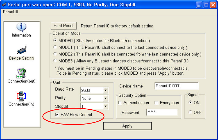
C.1 ON/OFF of Hardware Flow Control
Parani10 is designed to use CTS/RTS for handshaking. For equipment that is not using
Hardware flow control for serial communications, Parani10’s firmware should be set to turn OFF
hardware flow control (CTS/RTS).
Customers may indicate preferences when ordering or turn off the handshaking by bridging CTS
and RTS (no. 7 and no. 8 lines) using a Gender changer.
Parani10 has automatic detection feature of hardware flow control, but in certain environment
such as PC, this function may not operate correctly.
* Customers may choose the usage of hardware flow control using Para
ni10_Manager
software.
If checked, Parani10 will use hardware flow control. If you do not want to use the function,
please uncheck and press Apply button.
43
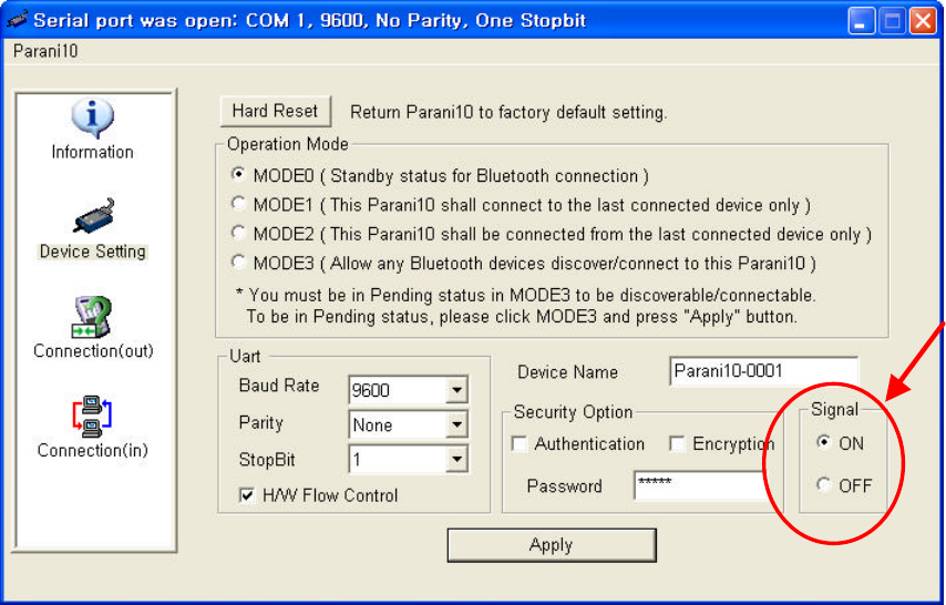
C.2 Enabling/Disabling of Response Signals OK, CONNECT &
ERROR
Parani10 will respond to users on the current status, success & failure of connections, and error
mode. Both Parani10_Manager and Terminal Programs will receive related response signals
from Parani10.
In some cases, various equipment may regard these four response signals incorrectly and react
inappropriately. To avoid these possible errors, users may disable the response signals via
Parani10_Manager or AT commands at Terminal.
1) By Parani10_Manager, check OFF at Signal pane at Device Setting panel to disable 4
response signals from Parani10.
2) By AT commands at your Terminal program.
ATS10=1 : Enabling/ON 4 signals
ATS10=0 : Disabling/OFF 4 signals
ATS10? : To see current status
44
C.3 For DCE connection
Parani10 is twisted Rx/Tx-ready for direct DTE connection. For connection to DCE equipment
such as modem etc., customers need to use a gender changer that twisted Tx/Rx, CTS/RTS,
and DTR/DSR for correct operation.
For more information, please contact support@sena.com
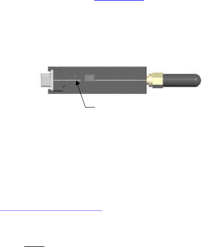
C.4 Hardware Reset
For Hardware reset, press the button on the right side of the Parani10 unit with a narrow tool
such as a ballpoint pen.
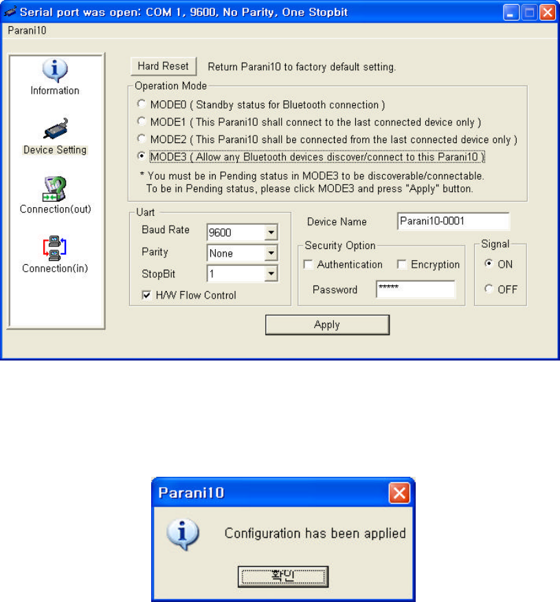
C.5 How to get Bluetooth CF cards connected to Parani10
If you are using Bluetooth CF cards or USB adaptors from other manufacturers, please use
Parani10_Manager software of latest version, which will be more familiar to consumers.
Parani10_Manager can be downloaded from our website at:
http://www.sena.com/support/downloads
1) In Parani10_Manager, start and go to the Device Setting menu.
2) Select MODE3 to allow any Bluetooth device can discover and connect to this Parani10.
HARD
RESET SWITCH
45
3) Press “Apply” button.
4) You will get Configuration has been applied message.
5) If you confirm, the page will show the current device information as in below.
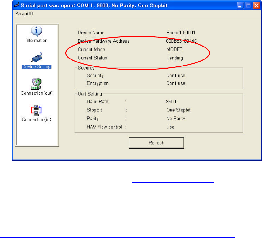
46
6) Please CONFIRM that now the Parani10 is in MODE3 and PENDING status as
displayed in the Red circle above. If the Parani10 is in STANBY status, connection WILL NOT
be made.
7) At this stage, Parani10 is DICOVERABLE & CONNECTABLE MODE
Get your Bluetooth CF cards or USB adaptors connected to this Parani10 now. To finish
connecting your Bluetooth devices to Parani10, open your COM port of Serial Communication
program to verify communication status.