SENA TECHNOLOGIES PARANISD100 Bluetooth RS232C Serial Adaptor User Manual manual parani sd100 v2 0 2
Sena Technologies,Inc. Bluetooth RS232C Serial Adaptor manual parani sd100 v2 0 2
Users Manual

USER MANUAL
Version 2.0.2 (2006.05.22)
Parani SD™
100
Bluetooth RS232C Serial Adaptor
by Bluetooth
Enabling Wireless Serial Communications

FCC CONCERNS
FCC Compliance Statement
This device complies with part 15 of the FCC Rules. Operation
is subject to the following two conditions:
(1) This device may not cause harmful interference, and
(2) This device must accept any interference received,
including interference that may cause undesired operation.
This equipment has been tested and found to comply with the limits for a Class B digital device, pursuant
to part 15 of the FCC Rules. These limits are designed to provide reasonable protection against harmful
interference in a residential installation.
This equipment generates, uses and can radiate radio frequency energy and, if not installed and used in
accordance with the instructions, may cause harmful interference to radio communications. However, there is
no guarantee that interference will not occur in a particular installation. If this equipment does cause
harmful interference to radio or television reception, which can be determined by turning the equipment off
and on, the user is encouraged to try to correct the interference by one or more of the following measures:
- Reorient or relocate the receiving antenna.
- Increase the separation between the equipment and receiver.
- Connect the equipment into an outlet on a circuit different from that to which the receiver
is connected.
- Consult the dealer or an experienced radio/TV technician for help.
RF Exposure Statement:
The equipment complies with FCC RF radiation exposure limits set forth for an uncontrolled
environment. This device and its antenna must not be co-located or operating in conjunction
with any other antenna or transmitter.
Do not
Any changes or modifications to the equipment not expressly approved by the
party responsible for compliance could void user’s authority to operate the
equipment.
Parani-SD100 User Manual – Table of Contents 1
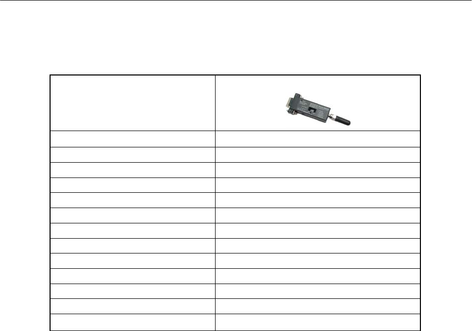
z Parani-SD100
Bluetooth Serial Adaptor
SD100
Part Number
Description External type wireless serial adapter with dip switch
Power Class Class1
RF Range Up to 100m
Power Connector DC plug or 9 pin
Power supply DC5V / 2A (AC100~240V / 50Hz~60Hz)
Serial connector Female DB9
Serial Interface RS-232
Dip switch Yes (4 slots)
Profile Serial Port Profile
Applicable Antenna Stub Antenna, Dipole Antenna, Patch Antenna
Dimensions (H¯W¯D) 62.5x31.2x16.3
Includes Helical Antenna, DC power cable

Parani-SD100 User Manual – Table of Contents 2
Table of Contents
1. Getting Started
Components --------------------------------------------------------4
Assembly ------------------------------------------------------------- 4
Locating the Controls ------------------------------------------ 5
2. Configurations
Operation Modes ------------------------------------------------- 7
LED Indicators -----------------------------------------------------8
Serial Ports ---------------------------------------------------------- 8
Reset to Factory Defaults ------------------------------------- 8
Terminal Program ------------------------------------------------ 9
Dip Switch ------------------------------------------------------------- 10
Pairing Button ----------------------------------------------------------10
3. Connections
RS232 Interface --------------------------------------------------- 13
Pin Assignment ---------------------------------------------------- 14
Power Supply ------------------------------------------------------15
4. Specifications
Bluetooth ----------------------------------------------------------- 17
Serial Interface --------------------------------------------------- 17
Power ---------------------------------------------------------------- 17
Mechanical Dimensions ---------------------------------------- 17
Environmental --------------------------------------------------- 17
Default Antenna -------------------------------------------------18
Wireless Coverage ---------------------------------------------- 18
Appendix A. AT Commands
Terminology ------------------------------------------------------- A-2
Command Description --------------------------------------- A-3

Parani-SD100 User Manual – 1. Getting Started 3
1. Getting Started
z Components
z Assembly
z Locating the Controls
Parani-SD100 User Manual – 1. Getting Started 4
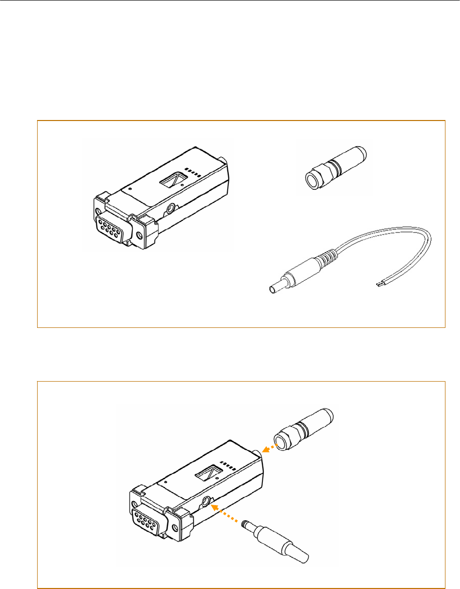
Components
Assembly
Parani-SD100
Helical Antenna
DC 5V Power Cable
Fig.1-1 Components of Prani-SD100
※ Antenna is left-hand threaded.
Fig.1-2 Assembly of Prani-SD100
※ Use of non-authorized power
adapter is not recommended.
Parani-SD100 User Manual – 1. Getting Started 5
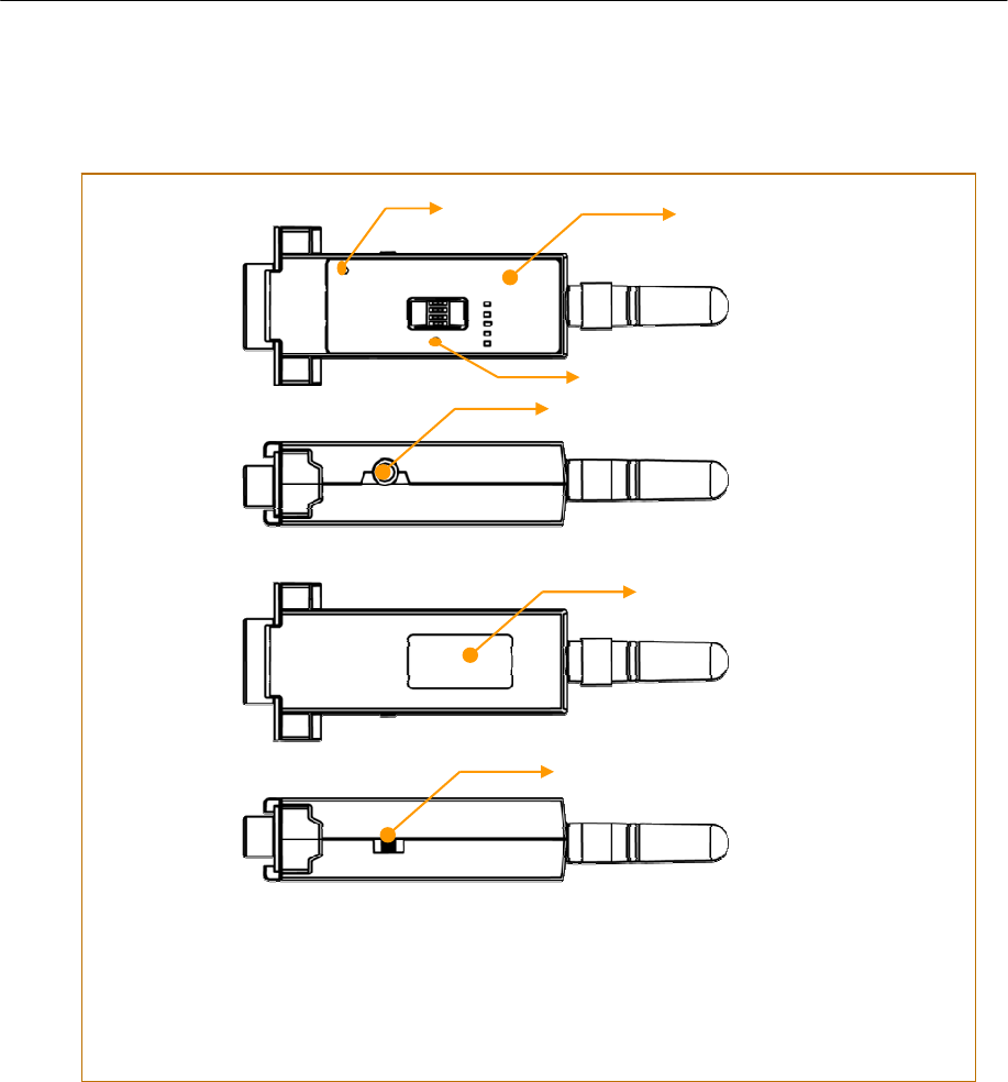
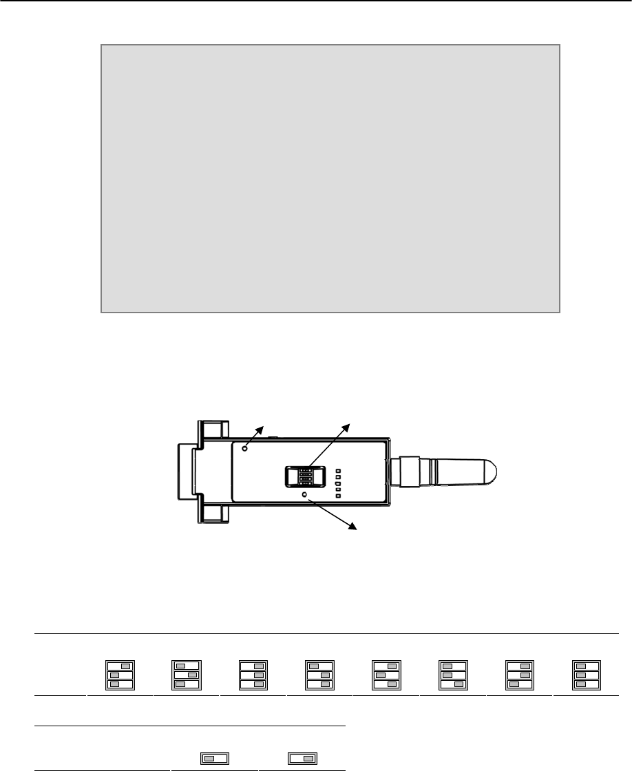
Locating the Controls
Fig.1-3 Locating the Controls
Front Panel †
Power Jack
Back Label ‡
Power Switch
Reset Button
Pairing Button

Parani-SD100 User Manual – 2. Configurations 6
2. Configurations
z Operation Modes
z LED Indicators
z Serial Ports
z Reset to Factory Defaults
z Terminal Program
z Dip Switch
z Pairing Button

Parani-SD100 User Manual – 2. Configurations 7
Operation Modes
In addition to the serial port configurations such as bit/second, data bit, parity, stop bit, flow control, Parani-SD has
some configurations for Bluetooth. For getting the most out of Parani-SD100, user should understand the following
Bluetooth connection schemes.
A Bluetooth device can play a role as a master or slave. Master tries to connect itself to other Bluetooth device, and
slave is waiting to be connected from other Bluetooth devices. A Bluetooth connection is always made by a pair of
master and slave. A slave can be in two modes, Inquiry Scan or Page Scan mode. Inquiry Scan mode is waiting the
packet of inquiry from other Bluetooth devices and Page Scan mode is waiting the packet of connection from other
Bluetooth devices. Every Bluetooth device has its unique address, called BD (Bluetooth Device) address, which is
composed of 12 hexa-decimal numbers.
Parani-SD100 has 4 operation modes as follows. Each mode can be identified with LED indicators as illustrated in next
section.
Ì Mode0
Parani-SD100 must be in Mode0, when it is directly controlled by AT commands.
In this mode, there is no response when power on or software reset, and Parani-SD100 is just waiting for AT command
input. Neither master nor slave is assigned to Parani-SD100 in mode0. User can change the configurations of Parani-
SD100 in this mode.
The factory default is set to Mode0.
Ì Mode1
Parani-SD100 tries to connect the last connected Bluetooth device.
Parani-SD100 in Mode1 is to be a master and tries to connect the last connected Bluetooth device. Parani-SD100
always stores the BD address of the Bluetooth device to which Parani-SD100 has connected last time. When Parani-
SD100 is initially used or after hardware reset, there is no BD address stored in Parani-SD100. In this case, Mode1 does not
make any sense and mode change from other operation modes to Mode1 is not allowed. The mode change to
Mode1 can be made after Parani-SD100 succeeds to connect to other Bluetooth device in Mode0. Once changed to
Mode1, Parani-SD100 will try to connect automatically the last connected Bluetooth device whenever power on or
software reset.
Parani-SD100 in Mode1 cannot be discovered or connected by other Bluetooth devices.
Ì Mode2
Parani-SD100 is waiting for the connection from the last connected Bluetooth device.
Parani-SD100 in Mode2 is to be a slave and waiting for the connection only from the last connected Bluetooth device.
Just like Mode1, if there is no BD address stored in Parani-SD100, the mode change from other operation modes to
Mode2 is not allowed. Once changed to Mode2, Parani-SD100 will wait for the connection from the last connected
Bluetooth device whenever power on or software reset.
Parani-SD100 in Mode2 cannot be discovered or connected to Bluetooth devices other than the last connected
device.
Ì Mode3
Parani-SD100 is waiting for the connection from any other Bluetooth devices.
Parani-SD100 in Mode3 acts like in Mode2, but allows any connection from other Bluetooth device. Most of general
Bluetooth device is set to Mode3.
Parani-SD100 in Mode3 can be discovered and connected from any other Bluetooth devices.
Parani-SD100 User Manual – 2. Configurations 8
LED Indicators
Indicator Power LED Standby LED Connect LED
Mode0 Green ┏━━━━━━━ Red ┏━━━━━━━
Mode1 Green ┏━━━━━━━ Green (every 1 sec) ┏┓
Mode2 Green ┏━━━━━━━ Green (every 3 sec) ┏┰┓
Mode3 Green ┏━━━━━━━ Green (every 3 sec) ┏┰┓
Connected Green ┏━━━━━━━ Green ┏━━━━━━━
RS232-Tx and RS232-Rx LED are blinking accordingly when data is transmitted. For small data transmission, it may be
hard to recognize the quick blinking.
Serial Ports
The applicable settings for serial ports are as follows.
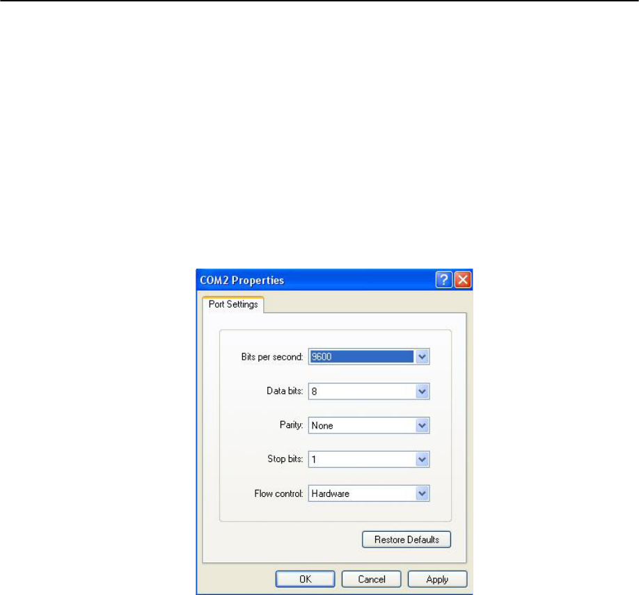
Serial Port Settings Values
Baud rate 1200, 2400, 4800, 9600 , 19200, 38400, 57600, 115200, 230400
Data bit 8
Parity No parity , Even parity, Odd parity
Stop bit 1 , 2
Hardware Flow Control Use , No use
The values in box are the factory defaults.
Ì Data Bit
Parani-SD100 supports only 8 data bit. In the case of 7 data bit, please contact the technical support.
Ì Hardware Flow Control
Parani-SD100 plugged into its host system transmits data from host to the other side Bluetooth device. These data is
saved temporarily in the internal buffer of Parani-SD100 and sent repeatedly until the transmission is completed packet
by packet. When the radio transmission condition is not good enough to send data promptly, it can cause the
transmission delay. If the host sends more data when the buffer is full, buffer overflow will make Parani-SD100
malfunction consequently. In order to prevent this buffer overflow, Parani-SD100 works as follows.
In case of using hardware flow control, Parani-SD100 makes RTS be ‘disable’ to stop receiving further data from the host
when the buffer becomes full. RTS will be ‘able’ to begin receiving data again from the host when the buffer has some
room for more data.
In case of not using hardware flow control, Parani-SD100 clears the buffer to secure the room for next data when the
buffer becomes full. This means the loss of data. As the transmission data becomes large, the possibility of data loss
goes higher.
For large data transmission, use of hardware flow control is highly recommended.
Reset to Factory Defaults
To turn back all the configurations to its factory settings, press the reset button depicted in Fig. 1-3. Press the reset
button with a narrow pointed tool like paper clip longer than 1 second. Reset works only when power is on.
Parani-SD100 User Manual – 2. Configurations 9
Terminal Program
A terminal Tprogram is an application that will enable a PC to Tcommunicate directly with a modem. If you are using
Windows 98SE or higher version of Windows, HyperTerminal program as it is included as part of the operating system.
Parani-SD100 provides some extended AT commands for its configurations on terminal program.
This manual will explain the method using HyperTerminal. If you need to install HyperTerminal, click start>setting>control
panel>add/remove programs. For more precise information, please refer to Help of Microsoft Windows.
Attach Parani-SD100 to serial port of host computer and power on. Standby LED is lit in green.
Launch HyperTerminal. It can be found in start >programs >accessories >communication >HyperTerminal. Select the
Serial port that Parani-SD100 will be connected to.
Input the same settings into Serial port configuration window as Parani-SD100 settings.
The settings need to be set correctly, otherwise, error message may be shown up on the screen or cause
malfunctioning of Parani-SD100.
Choose the settings in File->Properties->Settings->ASCII setup that let you turn echo on in HyperTerminal; this will show
the response Parani-SD100 sends on the screen.
You now get the HyperTerminal window where you are able to control Parani-SD100 with AT commands. For expanded
AT commands that Parani-SD100 provides, please refer to Appendix A. AT commands.
Example of AT commands:
Parani-SD100 User Manual – 2. Configurations 10
Dip Switch
With the combination of 4 slot dip switches, baud rate and hardware flow control can be set simply without host
computer.
Upper 3 dip switches are used for setting baud rate, and bottom dip switch is used for setting hardware flow control
option. If the baud rate needs to be set out of the range given below, PromiWIN or terminal program should be used
for extended AT commands. At this time combination of dip switches must be complied with AT cmd. Then baud rate
will go back to 9600 as default.
2400 4800 9600 19.2K 38.4K 57.6K 115.2K AT cmd
Baud
Rate
No use Use
Hardware Flow Control
Handshaking
Pairing Button
Parani-SD100 provides Pairing Button for instant configuration without PC to make an automatic connection between
two Parani-SD100s. For convenience sake, name two Parani-SD100s as SD1 and SD2 respectively.
1. Turn off all the nearby Parani-SD100
2. Turn on SD1 and SD2 and hardware reset both of them by pressing Reset Button.
3. Press the Pairing Button of SD1 for 2 seconds until Standby LED turns off and Connect LED blinks 3 times every
2 seconds. Keep the power ON.
AT+BTINFO?
000195000509,PSDv3b-000509,MODE0,STANDBY,0,0,HWFC
OK
AT+BTINQ?
00019520007E,PSDv2a-20007E,001F00
0004B300E205,AP2002:1 #0,020300
OK
ATD00019520007E
OK
CONNECT 0001952007E
Pairing Button
Dip Switch
Reset Button

Parani-SD100 User Manual – 2. Configurations 11
4. Press the Pairing Button of SD2 for 2 seconds until Standby LED turns off and Connect LED blinks 3 times every
2 seconds. Now press again the Pairing Button for 2 seconds until Connect LED blinks every 0.5 second.
5. Wait for SD1 & SD2 to be connected for a while until Connect LED’s of SD1 and SD2 is lit in green. It takes
about 10 seconds to make a connection. If there are many Bluetooth devices nearby, it will take a little bit
more.
6. Turn SD1 off and on. Connect LED blinks twice in green every 3 seconds.
7. Turn SD2 off and on. Connect LED blinks once in green every 1 second.
8. Now a pair of Parani-SD100 is configured to make automatic connection, whenever power off and on.
9. Just use this pair of Parani-SD100 like virtual serial cable.
SD 1 status LED SD 2 status LED
1. hard reset Mode0 Standby LED turn on. 1. hard reset Mode0 Standby LED turn on.
2. push pairing
button
Mode3 Connect LED blinks 3
times every 2 sec.
2. push pairing
button
Mode3 Connect LED blinks 3
times every 2 sec.
3. 3. push pairing
button agian
Mode1 Connect LED blinks every
0.5 sec.
4. connected Slave Connect LED is lit in
green
4. connected Master Connect LED is lit in
green

Parani-SD100 User Manual – 3. Connections 12
3. Connections
z RS232 Interface
z Pin Assignment
z Power Supply
Parani-SD100 User Manual – 3. Connections 13
RS232C Interface
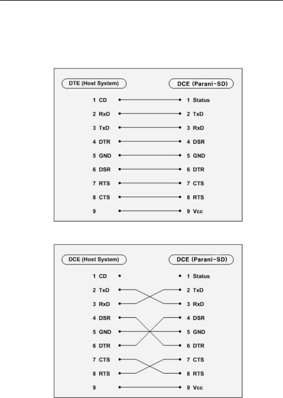
Ì DTE/DCE
If the full EIA232 standard is implemented as defined, the equipment at the far end of the connection is named the DTE
device (Data Terminal Equipment, usually a computer or terminal), has a male DB9 connector. Equipment at the near
end of the connection (the telephone line interface) is named the DCE device (Data Circuit-terminating Equipment,
usually a modem), has a female DB9 connector. The cable linking DTE and DCE devices is a parallel straight-through
cable with no cross-overs or self-connects in the connector hoods. If all devices exactly followed this standard, all
cables would be identical, and there would be no chance that an incorrectly wired cable could be used.
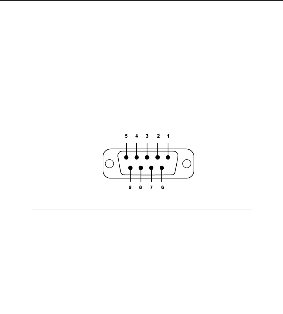
Ì DB9 Female
Parani-SD100 is a DCE device compatible with RS232 standard, having DB9 female interface.
Pin # Signal Direction Description
1 CD Output
Bluetooth Connect Status
2 TxD Output
Transmitted Data
3 RxD Input
Received Data
4 DSR Input
DTE Ready
5 GND - Signal Ground
6 DTR Output
DCE Ready
7 CTS Input
Clear to Send
8 RTS Output
Request to Send
9 Vcc Input
5V ~ 12v
Parani-SD100 User Manual – 3. Connections 14
Pin Assignment
Ì To Host with DTE Interface
Ì To Host with DCE Interface
Parani-SD100 User Manual – 3. Connections 15
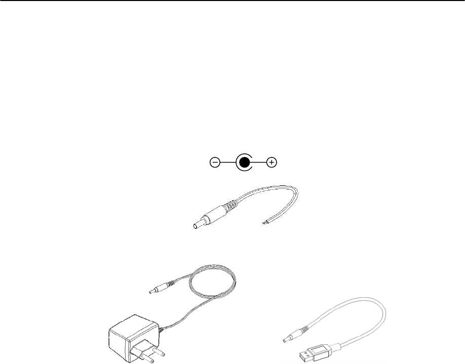
Power Supply
Parani-SD100 can be supplied power through the power jack and through pin 9 of DB9 connector.
Ì Through Power Jack
DC 5 V, Min. 150mA power should be supplied through DC power cable. Red cable is positive and black one is
negative.
AC/DC power adaptor and USB power cable are also available to supply power.
Ì Through Pin 9 of DB9 connector
The power can be supplied through pin 9 of DB9 connector. Because Parani-SD100 does not have any protection
circuit from surge, it must be constant voltage of 5 ~ 12V.
Electrical Polarity
DC Power Cable
AC/DC Power Adapter USB Power Cable
Red +
Black -

Parani-SD100 User Manual – 4. Specifications 16
4. Specifications
z Bluetooth
z Serial Interface
z Power
z Mechanical Dimensions
z Environmental
z Default Antenna
z Wireless Coverage
Parani-SD100 User Manual – 4. Specifications 17
Ì Bluetooth Interface
y Bluetooth 1.2 specification compatible and qualified
y Protocol: RFCOMM, L2CAP, SDP
y Profiles: Serial Port Profile, Generic Access Profile, Service Discovery Profile
y Radio Frequency: 2.402 ~ 2.480GHz
y Number of Channels: 79
y Transmission Power Class 1
y Data Transmission Rate: 380Kbps Max.
Ì Serial Interface
y EIA RS232C Standard
y Connector: DB9 female
y Data Transmission Rate: 1,200 ~ 230,400bps
y Hardware Flow Control: On/Off
Ì Power
y DC 5 V Constant Voltage
y Supply: DC Jack or Pin 9 of DB9
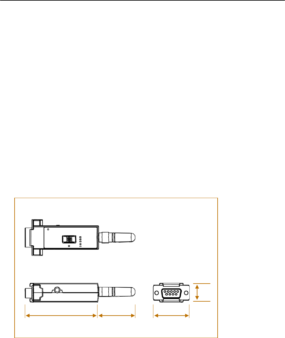
Ì Mechanical Dimensions
Ì Environmental
y Recommended Operational Temperature: -20℃ ~ 70℃
y Recommended Operational Humidity: 90% Max. Non-condensing
63mm 35mm
16mm
30mm

Parani-SD100 User Manual – 4. Specifications 18
Ì Default Antenna
y Type: Helical
y Frequency: 2,400 ~ 2,485GHz
y Gain: Max. 2dBi
y Impedance: 50Ω
y size: 30mm¯9mm (W¯D)
y weight: 3.5g
Ì Wireless Coverage
The table below shows the average measuring results in open space. These results can vary according to the
environmental conditions.
Antennas for two Parani-SD100
units Maximum Distance
Helical Antenna 100m

Parani-SD100 User Manual – Appendix A. AT Commands A-1
Appendix A. AT Commands
z Terminology
z Command Description

Parani-SD100 User Manual – Appendix A. AT Commands A-2
Terminology
Ì AT Command
AT command set is the HTde facto standardTH HTlanguageTH for controlling HTmodemsTH. The AT command set was developed by
HTHayesTH and is recognized by virtually all HTpersonal computerTH modems. Parani-SD100 provides the extended AT command
set to control and configure the serial parameters and Bluetooth connection.
Ì AT Response
Parani-SD100 replies to AT commands with 4 kinds of message, ‘OK’, ‘ERROR’, ‘CONNECT’ and ‘DISCONNECT’.
Ì Operation Mode
y Mode0: Waiting for AT commands
y Mode1: Attempting to connect to the last connected Bluetooth device
y Mode2: Waiting for the connection from the last connected Bluetooth device
y Mode3: Waiting for the connection from any other Bluetooth devices
Ì Operation Status
y Standby: Waiting for AT commands
y Pending: Executing tasks
y Connect: Transmitting data
Ì Security
y Authentication: Pin code (or Pass key)
y Encryption: Data encryption
Ì Symbols
The symbols are used for the description of command syntax as follows:
Symbol Meaning ASCII Code
Carriage return 0x0D
Line feed 0x0A
Carriage return + Line feed
112233445566 Bluetooth device address
n or m One digit decimal number
to Timeout in second

Parani-SD100 User Manual – Appendix A. AT Commands A-3
Command Description
1 ATZ
SD Response OK
Purpose Software Reset
Description This is the same effect as power off and on.
This command disconnects Bluetooth device, and stops ongoing task. After rebooting,
the status is decided by the preset operation mode.
Some AT commands need ATZ to take effect.
2 AT&F
SD Response OK
Purpose Hardware reset
Description This is the same effect as initialization by reset button.
All parameters are initialized to factory defaults. The storage of Parani-SD100 is cleared
completely.
3 AT
SD Response OK
Purpose Check the connection status with host equipment
Description Check if the connection to host equipment is normal. The serial parameters of Parani-
SD100 must be same as those of host equipment. If not, SD response is none or ‘ERROR’
or abnormal sequence of strings.
4 AT+UARTCONFIG,Baudrate,Parity,Stopbit
SD Response OK
Purpose Set Serial parameters
Parameters Baudrate=1200/2400/9600/14400/19200/38400/57600/115200/230400 (Default=9600)
Parity=N/E/O (Default=N)
Stopbit=1/2 (Default=1)
Description The Serial parameters can be set or changed. The factory default is 9600, N, 1.
To take effect of this command, ATZ or power off and on.
Example AT+UARTCONFIG,9600,N,1
5 AT+USEDIP?
SD Response m
Purpose Check the Baud rate set by dip switch
Description m=0: Set to ‘AT cmd’
m=1: Set to other than ‘AT cmd’

Parani-SD100 User Manual – Appendix A. AT Commands A-4
6 AT+BTINFO?
SD Response 112233445566,DeviceName,Mode,Status,Auth,Encryp,FlowControl
OK
Purpose Display Bluetooth settings
Description The current Bluetooth settings are displayed including BD address, Device name,
Operation mode, Operation status, Authentication, Data Encryption, and Hardware
Flow Control. The initial value of Device name is ‘PSDv3b-445566’. PSD stands for Parani-
SD100, v3b for the version of firmware, and 445566 for the last 6 digits of BD address.
Mode=MODE0/MODE1/MODE2/MODE3
Status=STANDBY/PENDING/CONNECT
Auth=0/1 (Authentication is not activated when 0)
Encrypt=0/1 (Encryption is not activated when 0)
FlowControl=HWFC/NoFC
Example 000B530011FF,SENA,MODE0,PENDING,1,1,HWFC
7 AT+BTINQ?
SD Response 112233445566,FriendlyName,CoD
112233445566,FriendlyName,CoD
112233445566,FriendlyName,CoD
OK
Purpose Search Bluetooth devices nearby
Description The Bluetooth devices in Inquiry scan mode nearby are displayed with their BD
addresses, Device names, and Class of device.
Maximum 10 devices are scanned for 30 seconds.
8 AT+BTLAST?
SD Response 112233445566
OK
Purpose Display the BD address of the last connected device
Description The Bluetooth device connected to this Parani-SD100 last time is displayed with its BD
address.
9 AT+BTMODE,n
SD Response OK
Purpose Set operation mode
Parameters n=0: MODE0 (Default)
n=1: MODE1
n=2: MODE2
n=3: MODE3
Description When the operation status is ‘Pending’ currently, change the status to ‘Standby’ with
AT+BTCANCEL prior to this command.
To take effect of this command, ATZ or power off and on.
Example AT+BTMODE,2
OK
ATZ

Parani-SD100 User Manual – Appendix A. AT Commands A-5
10 +++
SD Response OK
Purpose Convert the operation status of ‘Connect’ to ‘Standby’
Description In ‘Connect’ status, data from host is transmitted to the other side Bluetooth device,
and any AT command is not accepted but this command, which is not echoed on the
screen.
When Parani-SD100 encounters a character ‘+’ from host, it stops the data transmission
and waits for next 2 characters. If the next 2 characters aren’t both ‘+’, it restart to
transmit data including the first ‘+’ as well. If not, it converts the operation status to
‘Standby’.
If the data from host includes ‘+++’, it will convert the operation status to ‘Standby’
unexpectedly. Notice that Parani-SD100 holds data transmission when it encounters ‘+’,
until receiving next character.
‘+’ is an escape sequence character by default, which is changeable by AT+SETESC.
11 ATO
SD Response None
Purpose Convert the operation status of ‘Standby’ to ‘Connect’
Description You can convert the operation status of ‘Standby’ to ‘Connect’ ready to transmit data.
12 AT+BTCANCEL
SD Response OK
Purpose Terminate a current executing task
Description This terminates a current executing task, such as Inquiry scan and Page scan, then
converts the operation status to ‘Standby’.
Reference ATD, AT+BTINQ?, AT+BTCANCEL
Example AT+BTSCAN,2,30
Reference ATD, AT+BTINQ?, AT+BTCANCEL
Example AT+BTSCAN000B530011FF,30
13 ATD
SD Response OK
CONNECT 112233445566
or
OK
ERROR
Purpose Connect to the last connected Bluetooth device
Description Parani-SD100 saves the BD address of the Bluetooth device most recently connected.
ATD can make connection to it without input its BD address.
If it fails to make connection, SD response is ‘ERROR’.
14 ATD112233445566
SD Response OK

Parani-SD100 User Manual – Appendix A. AT Commands A-6
CONNECT 112233445566
or
OK
ERROR
Purpose Connect to the Bluetooth device with given BD address
Parameters 112233445566=BD address
Description Parani-SD100 attempts to connect to the Bluetooth device with the given BD address.
To make successful connection, the Bluetooth device must be in Page scan. This
attempt continues for 5 minutes.
If it fails to make connection, SD response is ‘ERROR’.
Example ATD000B530011FF
15 ATH
SD Response OK
DISCONNECT
Purpose Release the current connection
Description The current Bluetooth connection is released normally. It takes about 30 seconds to
detect an abnormal disconnection such as power off and moving out of service range.
16 AT+BTLPM,n
SD Response OK
Purpose Set low power mode
Parameters n=0: Inactivate (Default)
n=1: Activate
Description During no data transmission, Promi-SD can be in low power mode to save the power
consumption. It takes a few seconds to wake up Promi-SD in low power mode.
17 AT&V
SD Response S0:m0;S1:m1; …Sn:mn
OK
Purpose Display all the S-register
Description All parameters are stored at S-register in flash memory. These values are sustained until
hardware reset.
18 ATSnn?
SD Response value
OK
Purpose Display a given S-register
Parameters nn= Address of S-register
Description A specific S-register is displayed.
19 ATSnn=mm

Parani-SD100 User Manual – Appendix A. AT Commands A-7
SD Response OK
Purpose Change S-register value
Parameters nn= Address of S-register
mm= New value of S-register
Description Some S-registers are optimized for the overall performance and protected from an
arbitrary change by user. When users try to change these S-registers, SD response is
‘ERROR’.
For details of S-register, refer Appendix. B.
Example ATS10=0