SENA TECHNOLOGIES PARANISD1000 BLUETOOTH SERIAL ADAPTOR User Manual Parani SD1000 Manual
Sena Technologies,Inc. BLUETOOTH SERIAL ADAPTOR Parani SD1000 Manual
UserManual.wiki
>
SENA TECHNOLOGIES
>
PARANISD1000 User Manual
USERS MANUAL
Navigation menu
Upload a User Manual
Namespaces
Wiki Guide
HTML
PDF
Info
Views
User Manual
Discussion / Help
Navigation


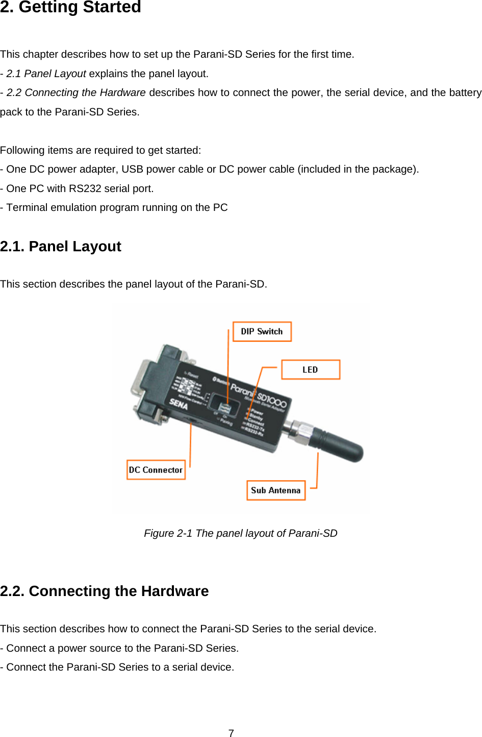
![8 2.2.1. Connecting Power to Parani-SD Connect the power jack to the power connector of the Parani-SD Series using the DC power adapter, USB power cable or DC power cable that is included in the package. If power is properly supplied, the [Power] lamp will display a solid green color. Figure 2-2 Connecting Power to Parani-SD 2.2.2. Connecting Device to Parani-SD Connect the serial device to the Parani-SD Series as shown below. Figure 2-3 Connecting a Serial Device to Parani-SD](https://usermanual.wiki/SENA-TECHNOLOGIES/PARANISD1000/User-Guide-953881-Page-8.png)