SENA TECHNOLOGIES PARANISD200 Bluetooth RS232C Serial Adaptor User Manual
Sena Technologies,Inc. Bluetooth RS232C Serial Adaptor
UserManual.wiki
>
SENA TECHNOLOGIES
>
PARANISD200 User Manual
Users Manual
Navigation menu
Upload a User Manual
Namespaces
Wiki Guide
HTML
PDF
Info
Views
User Manual
Discussion / Help
Navigation

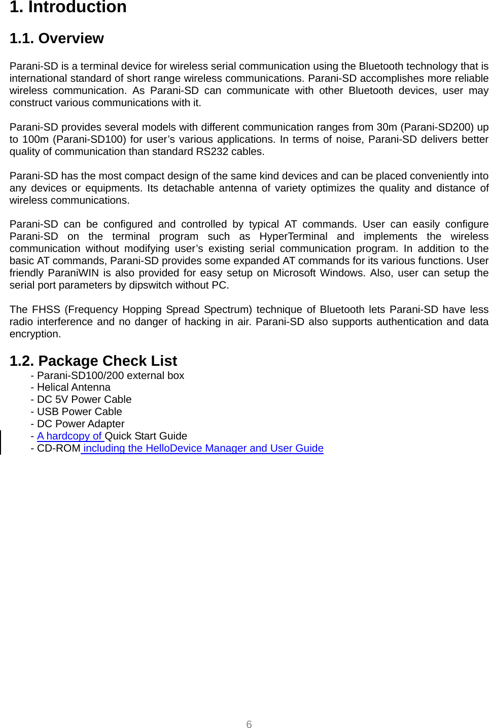
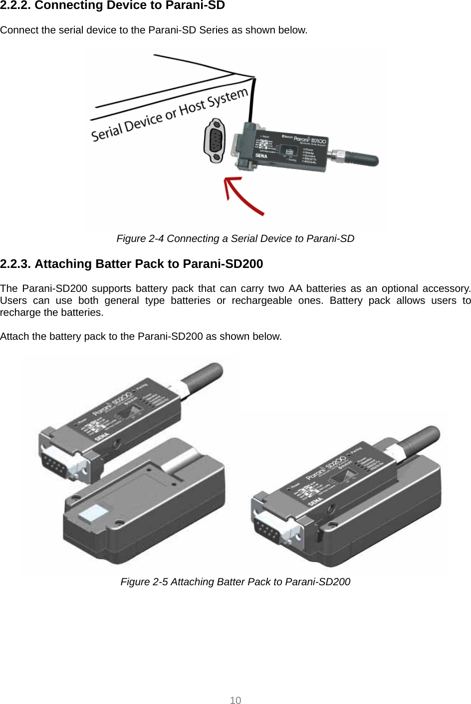
![9 Figure 2-2 The panel layout of Parani-SD200 2.2. Connecting the Hardware This section describes how to connect the Parani-SD Series to the serial device for initial testing. - Connect a power source to the Parani-SD Series. - Connect the Parani-SD Series to a serial device. 2.2.1. Connecting Power to Parani-SD Connect the power jack to the power connector of the Parani-SD Series using the DC power adapter, USB power cable or DC power cable that is included in the package. If power is properly supplied, the [Power] lamp will light up a solid green color. Figure 2-3 Connecting Power to Parani-SD200](https://usermanual.wiki/SENA-TECHNOLOGIES/PARANISD200/User-Guide-686932-Page-9.png)
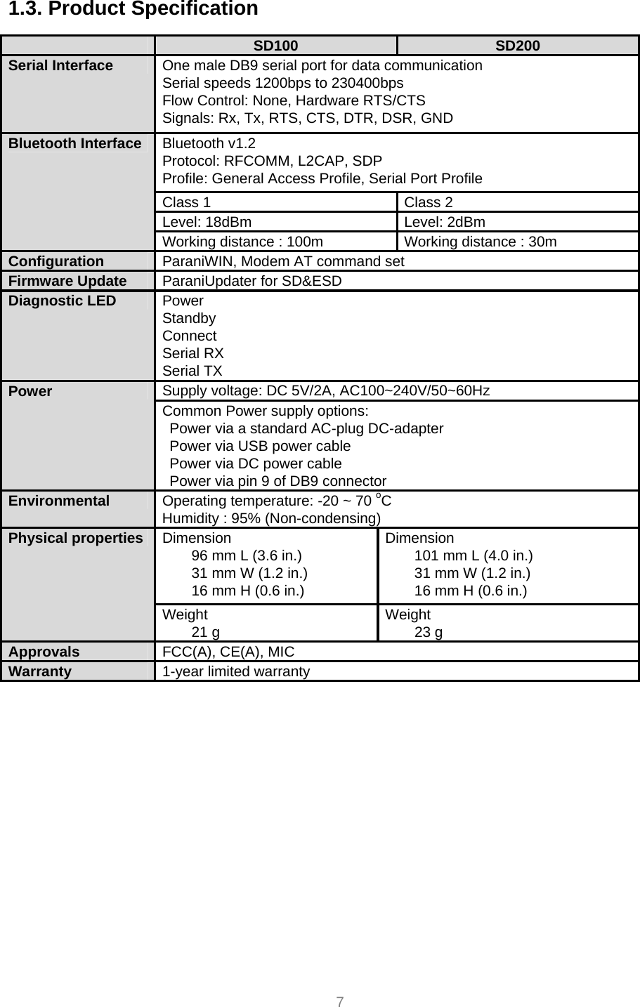
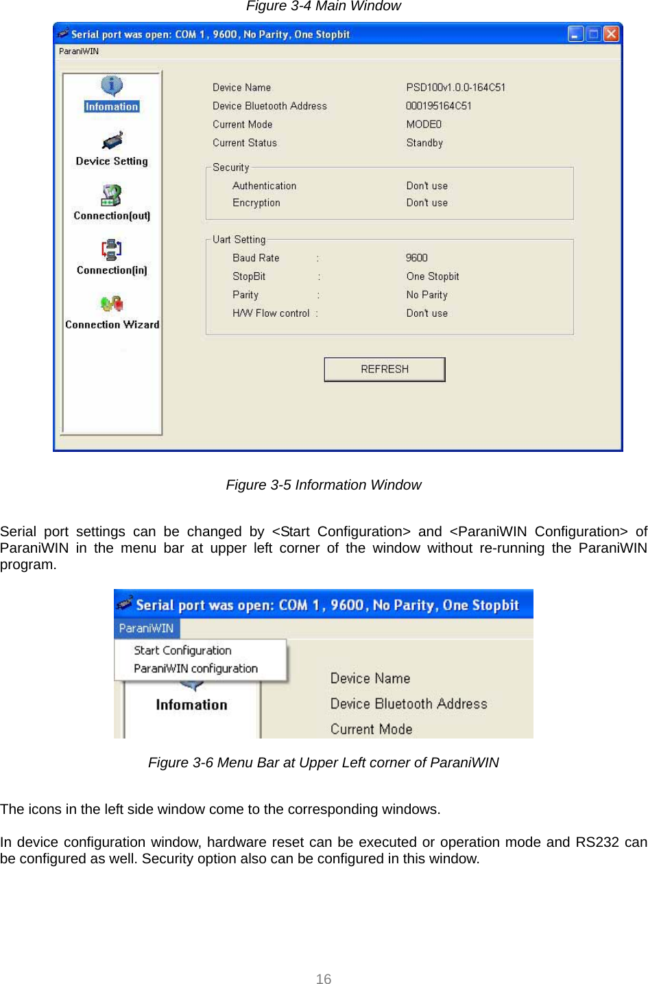
![15 Figure 3-2 Serial Port Setting Set each option properly and click [Confirm]. If the settings are different from the host computer, error message will pop up. If the Parani-SD is in the status of connection, warning message will pop up. Then the current connection can be cancelled by [Disconnect] button on the main window. Figure 3-3 Error Message Box](https://usermanual.wiki/SENA-TECHNOLOGIES/PARANISD200/User-Guide-686932-Page-15.png)
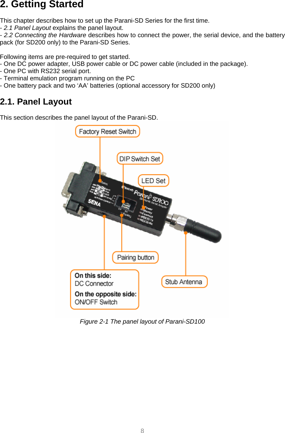
![17 Figure 3-7 Device Setting Window Parani-SD supports two security options, Authentication and Encryption. If you check the Authentication option, you must also enter the Pin Code value. If the authentication is activated, the connection, only between the Master and Slave device that share the same Pin Code, is established. In case that Parani-SD connects to other Bluetooth device that enables authentication, you must know the other device’s Pin Code. In general Bluetooth devices, 1234 or 0000 is used as a default value. If you check Encryption option, the Parani-SD encrypts packets and sends them. The Encryption options works well in case that only one between Master and Slave uses this option. Parani-SD has 4 response messages, ‘OK’, ‘ERROR’, ‘CONNECT’, and ‘DISCONNECT’. In some cases, these responses can affect the host system unexpectedly. To prevent this, user can set the Command response to ON or OFF. For Parani-SD100/200, hardware flow control can be configured only by dip switch. Thus H/W Flow Control option will not work in this case. When the dipswitch value isn’t ATcommand mode, the RS-232 menu will be disabled. Click [Apply] button to reflect the given options to Parani-SD actually. Connect(out) icon will show the following window to search and connect other Bluetooth devices.](https://usermanual.wiki/SENA-TECHNOLOGIES/PARANISD200/User-Guide-686932-Page-17.png)
![18 Figure 3-8 Connect(out) Window Click [Search] button to search nearby Bluetooth devices. The maximum number of devices to be searched can be controlled. Select one of the devices searched and click [Connect] button. The selected Bluetooth device must be in Page scan mode. Click [Disconnect] button to cancel the connection normally. After the connection is established, you are able to test sensitivity by pushing the START button.](https://usermanual.wiki/SENA-TECHNOLOGIES/PARANISD200/User-Guide-686932-Page-18.png)
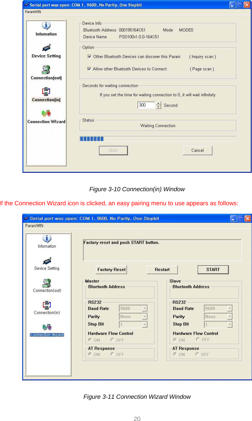
![19 Figure 3-9 Sensitivity Test The sensitivity test shows LInkQuality and RSSI values. The sensitivity is fine, If the LinkQuality is closer to 255 and RSSI is closer to 0. In general, the sensitivity is the best when the distance is 10 meters. You can push the STOP button in order to terminate the sensitivity test. The sensitivity test will continue until the STOP button is pushed. If you close the ParaniWIN Window without pushing the STOP button, you must restart Parani-SD to terminate the test. Connection(in) icon will show the following window to make Parani-SD wait to a connection from the other Bluetooth device. The waiting time in seconds can be controlled. With 0 input for this waiting time, Parani-SD keeps waiting for connection until [Cancel] button is clicked.](https://usermanual.wiki/SENA-TECHNOLOGIES/PARANISD200/User-Guide-686932-Page-19.png)