SENA TECHNOLOGIES PARANISD200L BLUETOOTH SERIAL ADAPTOR User Manual users manual
Sena Technologies,Inc. BLUETOOTH SERIAL ADAPTOR users manual
users manual
1
Parani-SD100L/200L
User Guide
Version 1.0.0
2006-09-18

2
User Guide for the Parani-SD100L/200L
Version 1.0.0
Firmware version 1.0.X
Last revised on June 14, 2006
Printed in Korea
Copyright
Copyright 2002, Sena Technologies, Inc. All rights reserved.
Sena Technologies reserves the right to make changes and improvements to its product without
providing notice.
Trademark
Parani™ is a trademark of Sena Technologies, Inc.
Windows® is a registered trademark of Microsoft Corporation.
Ethernet® is a registered trademark of XEROX Corporation.
Notice to Users
When a system failure may cause serious consequences, protecting life and property against such
consequences with a backup system or safety device is essential. The user agrees that protection
against consequences resulting from system failure is the user's responsibility.
This device is not approved for life-support or medical systems.
Changes or modifications to this device not explicitly approved by Sena Technologies will void the
user's authority to operate this device.
Precautions and Safety
Electricity
Use only the supplied AC adapter. Use of unauthorized power adapter is not recommended. Electrical
shock may result.
Do not kink or crease the power cable or place heavy objects on the power cable. Fire can result from
damaged power cables.
Do not handle power plug and adapter with wet hands. Electrical shock may result.
Immediately power off the product and unplug the AC adapter if smoke or odors emit from the product
and adapter. Fire can result from improper use.
Immediately power off the product and unplug the AC adapter if water or other liquids are present. Fire
can result from improper use.
Product
Parani-SD meets the RS-232 standards. Do not wire with non-standard products. Damage to your
products may result from improper use.
Do not drop or subject the device to impact. Damage to your products may result from improper use.
Keep away from harsh environments including humid, dusty, and smoky areas. Damage to your
products may result from improper use.
Do not use excessive force on the buttons or attempt to disassemble the device. Damage to your
products may result from improper use.
Do not place heavy objects on the product. Damage to your products may result from improper use.
Technical Support
Sena Technologies, Inc.
210 Yangjae-dong, Seocho-gu,
Seoul 137-130, Korea
Tel: (+82-2) 573-5422
Fax: (+82-2) 573-7710
E-Mail: support@sena.com
Website: http://www.sena.com
3
Contents
1. Introduction 6
1.1. Overview ...................................................................................................................................6
1.2. Package Check List....................................................................................................................6
1.3. Product Specification..................................................................................................................7
2. Getting Started 8
2.1. Panel Layout ..............................................................................................................................8
2.2. Connecting the Hardware ..........................................................................................................9
2.2.1. Connecting Power to Parani-SD......................................................................................9
2.2.2. Connecting Device to Parani-SD .....................................................................................9
2.2.3. Attaching Battery Pack to Parani-SD200LL.....오류! 책갈피가 정의되어 있지 않습니다.
3. Configuration 10
3.1. Operation Modes......................................................................................................................10
3.2. LED Indicators.......................................................................................................................... 11
3.3. Serial Ports............................................................................................................................... 11
3.3.1. Data Bit ..........................................................................................................................11
3.3.2. Hardware Flow Control .................................................................................................. 11
3.3.3. Reset to Factory Defaults ..............................................................................................12
3.3.4. Dipswitch........................................................................................................................12
3.3.5. Pairing Button ................................................................................................................13
3.3.6. Software and Utility........................................................................................................13
3.3.7. ParaniWIN......................................................................................................................14
3.3.8. ParaniUpdater................................................................................................................20
3.3.9. Terminal Program ..........................................................................................................20
4. Approval Information 22
4.1. FCC .................................................................................................................................22
4.1.1. FCC Compliance Statement ..........................................................................................22
4.1.2. RF Exposure Statement.................................................................................................22
4.1.3. Do not.............................................................................................................................22
4.2. CE .................................................................................................................................22
4.2.1. EC-R&TTE Directive......................................................................................................22
5. RF Information 23
5.1. Radio Frequency Range ..........................................................................................................23
5.2. Number of Frequency Channel................................................................................................23
5.3. Transmission Method ...............................................................................................................23
5.4. Modulation Method...................................................................................................................23
5.5. Radio Output Power.................................................................................................................23
5.6. Receiving Sensitivity ................................................................................................................23
5.7. Power Supply ...........................................................................................................................23
Appendix A: Connections 24
A.1. Serial Port Pin Outs .................................................................................................................24
A.2. Serial Wiring Diagram..............................................................................................................24
A.2.1. To Host with DTE Interface............................................................................................25
A.2.2. To Host with DCE Interface ...........................................................................................25
Appendix B: AT Commands 26
B.1. Terminology..............................................................................................................................26
B.1.1. AT Command.................................................................................................................26
B.1.1. AT Response .................................................................................................................26
B.1.2. Operation Mode.............................................................................................................26
B.1.3. Operation Status............................................................................................................26
B.1.4. Security..........................................................................................................................26
B.1.5. Symbols.........................................................................................................................27
B.2. Command Category.................................................................................................................27
B.3. Command Description .............................................................................................................28
B.3.1. ATZ..............................................................................................................................28
4
B.3.2. AT&F............................................................................................................................28
B.3.3. AT.................................................................................................................................28
B.3.4. AT+UARTCONFIG,Baudrate,Parity,Stopbit.................................................................28
B.3.5. AT+USEDIP?...............................................................................................................29
B.3.6. AT+BTINFO?...............................................................................................................29
B.3.7. AT+BTINQ?.................................................................................................................29
B.3.8. AT+BTLAST?...............................................................................................................29
B.3.9. AT+BTVER?................................................................................................................30
B.3.10. AT+BTRSSI,n............................................................................................................30
B.3.11. AT+BTMODE,n..........................................................................................................30
B.3.12. +++............................................................................................................................30
B.3.13. AT+SETESC,nn.........................................................................................................31
B.3.14. ATO............................................................................................................................31
B.3.15. AT+BTCANCEL.........................................................................................................31
B.3.16. AT+BTSCAN..............................................................................................................31
B.3.17. AT+BTSCAN,n,to.......................................................................................................32
B.3.18. AT+BTSCAN112233445566,to..................................................................................32
B.3.19. ATD............................................................................................................................32
B.3.20. ATD112233445566....................................................................................................33
B.3.21. ATH............................................................................................................................33
B.3.22. AT+BTKEY=$string....................................................................................................33
B.3.23. AT+BTSD? ................................................................................................................34
B.3.24. AT+BTCSD................................................................................................................34
B.3.25. AT+BTFP,n.................................................................................................................34
B.3.26. AT+BTSEC,Authentication,Encryption......................................................................34
B.3.27. AT+BTNAME=$string................................................................................................35
B.3.28. AT+BTLPM,n.............................................................................................................35
B.3.29. AT+DFU.....................................................................................................................35
B.3.30. AT&V..........................................................................................................................35
B.3.31. ATSnn? .....................................................................................................................35
B.3.32. ATSnn=mm................................................................................................................36
B.4. Command Validity....................................................................................................................36
Appendix C: S-Register 38
C.1. S1: Force to Reconnect (default 1)..........................................................................................38
C.2. S2: Enable Hardware Flow Control (default 1)........................................................................38
C.3. S3: Stream UART Policy (default 0) ........................................................................................38
C.4. S4: Enable Remote Name Query (default 1)...........................................................................38
C.5. S6: Enable Low Power Mode (default 0).................................................................................39
C.6. S10: Enable SD Response (default 1) ....................................................................................39
C.7. S11: Enable Escape (default 1)...............................................................................................39
C.8. S12: Clear Data Buffer When Disconnected (default 0)..........................................................39
C.9. S14: Enable DTR Transfer (default 1) .....................................................................................39
C.10. S15: Enable Disconnect by DTR (default 0)..........................................................................39
C.11. S22: Fast Connect (default 0)................................................................................................39
C.12. S24: Maximum Number of Inquiry Result (default 10) ..........................................................40
C.13. S28: Escape Sequence Character (default 43).....................................................................40
C.14. S31: Page Timeout (default 300)...........................................................................................40
C.15. S33: Inquiry Timeout (default 30) ..........................................................................................40
C.16. S37: Supervision Timeout (default 16000) ............................................................................40
C.17. S46: BD Address of Last Connected Device.........................................................................40
Appendix D: Trouble Shooting 41
D.1 No Data Transmission ..............................................................................................................41
D.1.1 COM Port Settings .........................................................................................................41
D.1.2 Pin Assignment...............................................................................................................41
D.2 Data Loss or Malfunctioning.....................................................................................................41
D.2.1Hardware Flow Control....................................................................................................41
5
D.2.2 AT Response ..................................................................................................................41
D.3 Transmission Delay ..................................................................................................................42
D.3.1 RF Processing Delay......................................................................................................42
D.3.2 RF Transmission Environment .......................................................................................42

6
1. Introduction
1.1. Overview
Parani-SD is a terminal device for wireless serial communication using the Bluetooth technology that is
international standard of short range wireless communications. Parani-SD accomplishes more reliable
wireless communication. As Parani-SD can communicate with other Bluetooth devices, user may
construct various communications with it.
Parani-SD provides several models with different communication ranges from 30m (Parani-SD200L)
up to 100m (Parani-SD100L) for user’s various applications. In terms of noise, Parani-SD delivers
better quality of communication than standard RS232 cables.
Parani-SD has the most compact design of the same kind devices and can be placed conveniently into
any devices or equipments. Its detachable antenna of variety optimizes the quality and distance of
wireless communications.
Parani-SD can be configured and controlled by typical AT commands. User can easily configure
Parani-SD on the terminal program such as HyperTerminal and implements the wireless
communication without modifying user’s existing serial communication program. In addition to the
basic AT commands, Parani-SD provides some expanded AT commands for its various functions. User
friendly ParaniWIN is also provided for easy setup on Microsoft Windows. Also, user can setup the
serial port parameters by dipswitch without PC.
The FHSS (Frequency Hopping Spread Spectrum) technique of Bluetooth lets Parani-SD have less
radio interference and no danger of hacking in air. Parani-SD also supports authentication and data
encryption.
1.2. Package Check List
- Parani-SD100L/200L external box
- Stub Antenna
- DC 5V Power Cable
- USB Power Cable
- DC Power Adapter
- A hardcopy of Quick Start Guide
- CD-ROM including the HelloDevice Manager and User Guide
7
1.3. Product Specification
SD100L SD200L
Serial Interface One male DB9 serial port for data communication
Serial speeds 1200bps to 230400bps
Flow Control: None, Hardware RTS/CTS
Signals: Rx, Tx, RTS, CTS, DTR, DSR, GND
Bluetooth v1.2
Protocol: RFCOMM, L2CAP, SDP
Profile: General Access Profile, Serial Port Profile
Class 1 Class 2
Level: 18dBm Level: 2dBm
Bluetooth Interface
Working distance : 100m Working distance : 30m
Configuration ParaniWIN, Modem AT command set
Firmware Update ParaniUpdater for SD&ESD
Diagnostic LED Power / Charging finish
Standby / Charging
Connect
Serial RX
Serial TX
Supply voltage: DC 5V/2A, AC100~240V/50~60Hz
Battery voltage : DC 4.2V / 230mA
Power
Common Power supply options:
Power via a standard AC-plug DC-adapter
Power via USB power cable
Power via DC power cable
Power via pin 9 of DB9 connector
Environmental Operating temperature: -10 ~ 55 oC
Humidity : 95% (Non-condensing)
Dimension
96 mm L (3.6 in.)
31 mm W (1.2 in.)
16 mm H (0.6 in.)
Physical properties
Weight
20 g Weight
23 g
Approvals FCC
Warranty 1-year limited warranty

8
2. Getting Started
This chapter describes how to set up the Parani-SD Series for the first time.
- 2.1 Panel Layout explains the panel layout.
- 2.2 Connecting the Hardware describes how to connect the power, the serial device, and the battery
pack to the Parani-SD Series.
Following items are pre-required to get started.
- One DC power adapter, USB power cable or DC power cable (included in the package).
- One PC with RS232 serial port.
- Terminal emulation program running on the PC
2.1. Panel Layout
This section describes the panel layout of the Parani-SD.
Figure 2-1 The panel layout of Parani-SD100L/200L
9
2.2. Connecting the Hardware
This section describes how to connect the Parani-SD Series to the serial device for initial testing.
- Connect a power source to the Parani-SD Series.
- Connect the Parani-SD Series to a serial device.
2.2.1. Connecting Power to Parani-SD
Connect the power jack to the power connector of the Parani-SD Series using the DC power adapter,
USB power cable or DC power cable that is included in the package. If power is properly supplied,
the [Power] lamp will light up a solid green color.
Figure 2-2 Connecting Power to Parani-SD200L
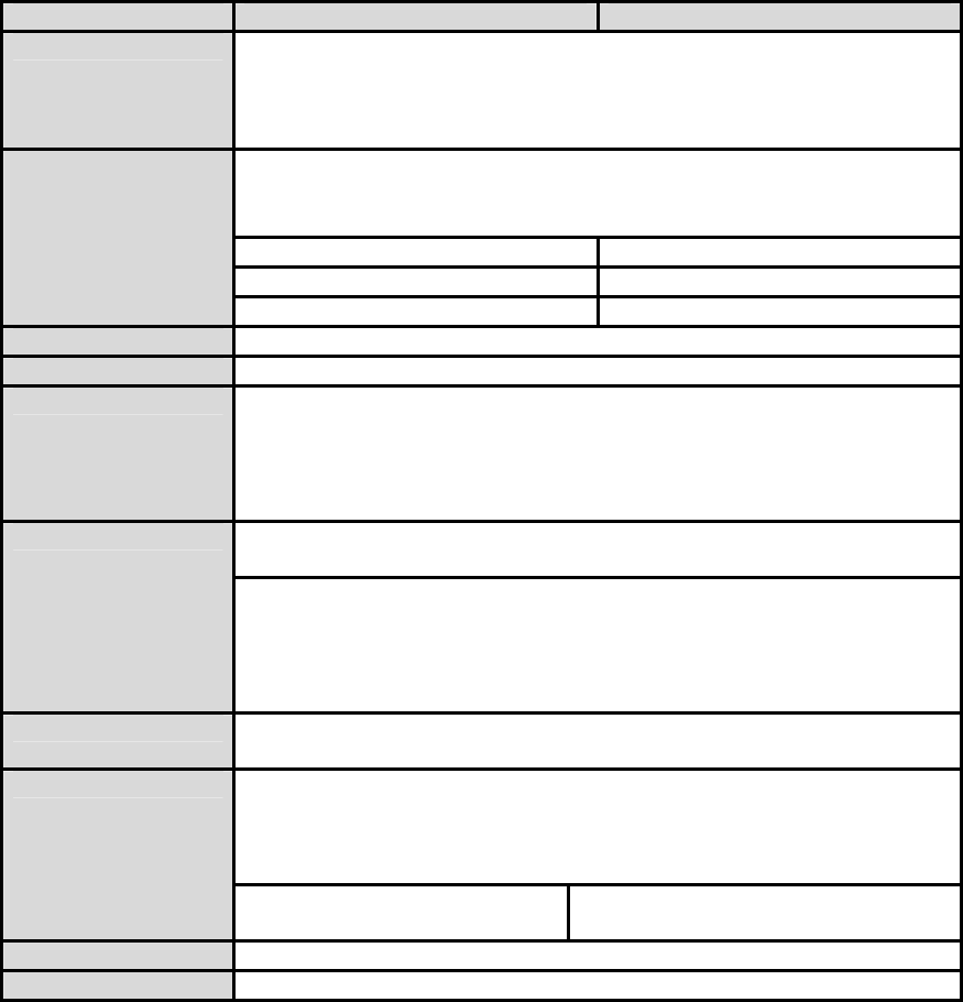
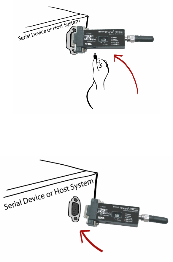
2.2.2. Connecting Device to Parani-SD
Connect the serial device to the Parani-SD Series as shown below.
Figure 2-3 Connecting a Serial Device to Parani-SD

10
3. Configuration
3.1. Operation Modes
In addition to the serial port configurations such as bit/second, data bit, parity, stop bit, flow control,
Parani-SD has some configurations for Bluetooth. For getting the most out of Parani-SD, user should
understand the following Bluetooth connection schemes.
A Bluetooth device can play a role as a master or slave. Master tries to connect itself to other
Bluetooth device, and slave is waiting to be connected from other Bluetooth devices. A Bluetooth
connection is always made by a pair of master and slave. A slave can be in two modes, Inquiry Scan
or Page Scan mode. Inquiry Scan mode is waiting the packet of inquiry from other Bluetooth devices
and Page Scan mode is waiting the packet of connection from other Bluetooth devices. Every
Bluetooth device has its unique address, called BD (Bluetooth Device) address, which is composed of
12 hexa-decimal numbers.
Parani-SD has 4 operation modes as follows. Each mode can be identified with LED indicators as
illustrated in next section.
Table 3-1 The Parani-SD Operation Modes
Mode Description
Mode0 Parani-SD must be in Mode0, when it is directly controlled by AT commands.
In this mode, there is no response when power on or software reset, and Parani-SD is just
waiting for AT command input. Neither master nor slave is assigned to Parani-SD in mode0.
User can change the configurations of Parani-SD in this mode.
The factory default is set to Mode0.
Mode1 Parani-SD tries to connect the last connected Bluetooth device.
Parani-SD in Mode1 is to be a master and tries to connect the last connected Bluetooth
device. Parani-SD always stores the BD address of the Bluetooth device to which Parani-SD
has connected last time. When Parani-SD is initially used or after hardware reset, there is no
BD address stored in Parani-SD. In this case, Mode1 does not make any sense and mode
change from other operation modes to Mode1 is not allowed. The mode change to Mode1 can
be made after Parani-SD succeeds to connect to other Bluetooth device in Mode0. Once
changed to Mode1, Parani-SD will try to connect automatically the last connected Bluetooth
device whenever power on or software reset.
Parani-SD in Mode1 cannot be discovered or connected by other Bluetooth devices.
Mode2 Parani-SD is waiting for the connection from the last connected Bluetooth device.
Parani-SD in Mode2 is to be a slave and waiting for the connection only from the last
connected Bluetooth device. Just like Mode1, if there is no BD address stored in Parani-SD,
the mode change from other operation modes to Mode2 is not allowed. Once changed to
Mode2, Parani-SD will wait for the connection from the last connected Bluetooth device
whenever power on or software reset.
Parani-SD in Mode2 cannot be discovered or connected to Bluetooth devices other than the
last connected device.
Mode3 Parani-SD is waiting for the connection from any other Bluetooth devices.
Parani-SD in Mode3 acts like in Mode2, but allows any connection from other Bluetooth
device. Most of general Bluetooth device is set to Mode3.
Parani-SD in Mode3 can be discovered and connected from any other Bluetooth devices.
11
3.2. LED Indicators
RS232-Tx and RS232-Rx LED are blinking accordingly when data is transmitted. For small data
transmission, it may be hard to recognize the quick blinking.
Table 3-2 The Parani-SD LED Indicators
Indicator Power / Charging finish
(Green LED) Standby / Charging
(Red LED) Connect LED
(Green LED)
Mode0 ┌┐┌┐┌┐┌┐┌┐ ┌┐┌┐┌┐┌┐┌┐
Mode1 ┌┐┌┐┌┐┌┐┌┐ Green (every 1 sec) ┏┓
Mode2 ┌┐┌┐┌┐┌┐┌┐ Green (every 3 sec) ┏┰┓
Mode3 ┌┐┌┐┌┐┌┐┌┐ Green (every 3 sec) ┏┰┓
Connected ┌┐┌┐┌┐┌┐┌┐ Green ┏━━━━━━━
Connected ┌┐┌┐┌┐┌┐┌┐ Green ┏━━━━━━━
Charging ┌┐┌┐┌┐┌┐┌┐ ┌─────────
Charging finish ┌─────────
3.3. Serial Ports
The applicable settings for serial ports are as follows.
Table 3-3 The Parani-SD Serial Port Settings
Serial Port Settings Values
Baud rate 1200, 2400, 4800, 9600, 19200, 38200, 57600, 115200, 230400
Data bite 8
Parity No parity, Even parity, Odd parity
Stop bit 1, 2
Hardware Flow Control Use, No Use
The values in box are the factory defaults. The flow control setting is configurable only through dip
switch.
3.3.1. Data Bit
Parani-SD supports only 8 data bit. In the case of 7 data bit, please contact the technical support.
3.3.2. Hardware Flow Control
Parani-SD plugged into its host system transmits data from host to the other side Bluetooth device.
These data is saved temporarily in the internal buffer of Parani-SD and sent repeatedly until the
transmission is completed packet by packet. When the radio transmission condition is not good
enough to send data promptly, it can cause the transmission delay. If the host sends more data when
the buffer is full, buffer overflow will make Parani-SD malfunction consequently. In order to prevent this
buffer overflow, Parani-SD works as follows.
12
In case of using hardware flow control, Parani-SD makes RTS be ‘disable’ to stop receiving further
data from the host when the buffer becomes full. RTS will be ‘able’ to begin receiving data again from
the host when the buffer has some room for more data.
In case of not using hardware flow control, Parani-SD clears the buffer to secure the room for next
data when the buffer becomes full. This means the loss of data. As the transmission data becomes
large, the possibility of data loss goes higher.
For large data transmission, use of hardware flow control is highly recommended.
3.3.3. Reset to Factory Defaults
To turn back all the configurations to its factory settings, press the reset button depicted in Fig. 1-3.
Press the reset button with a narrow pointed tool like paper clip longer than 1 second. Reset works
only when power is on.
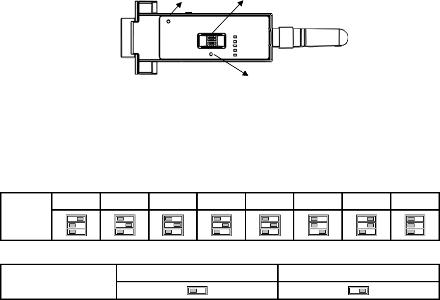
3.3.4. Dipswitch
This feature is only on Parani-SD205. With the combination of 4 slot dipswitches, baud rate and
hardware flow control can be set simply without host computer.
Figure 3-1 The Parani-SD Dipswitch
Upper 3 dipswitches are used for setting baud rate, and bottom dipswitch is used for setting hardware
flow control option. If the baud rate needs to be set out of the range given below, ParaniWIN or
terminal program should be used for extended AT commands. At this time combination of dipswitches
must be complied with AT cmd. Then baud rate will go back to 9600 as default.
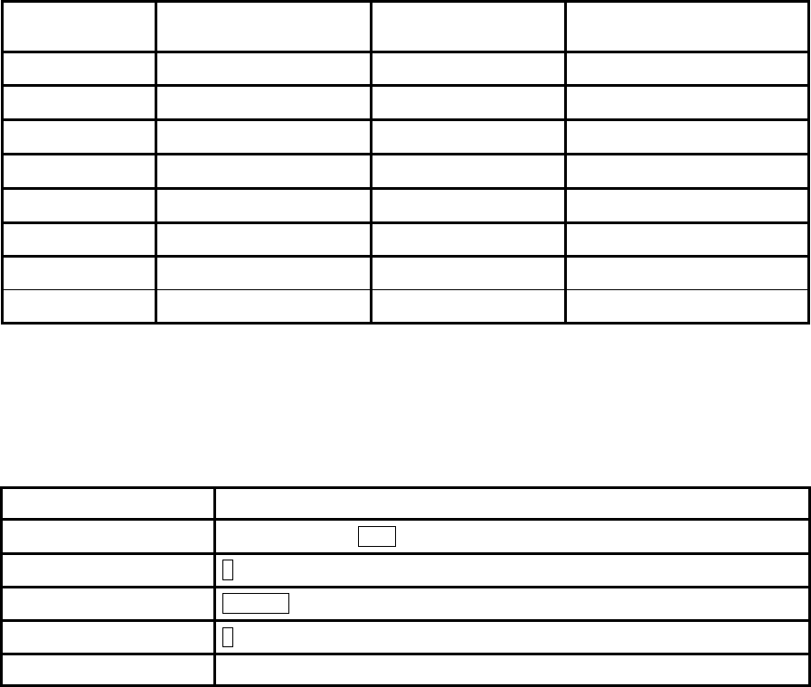
Table 3-4 Baud rate Settings by Dipswitches
2400 4800 9600 19.2K 38.4K 57.6K 115.2K AT cmd
Baud rate
Table 3-5 Hardware Flow Control Settings by Dipswitches
No Use Use
Hardware Flow Control
Handshaking
‘
Pairing Button
Dip Switch
Reset Button

13
3.3.5. Pairing Button
Parani-SD provides Pairing Button for instant configuration without PC to make an automatic
connection between two Parani-SDs. For convenience sake, name two Parani-SDs as SD1 and SD2
respectively.
Step 1. Turn off all the nearby Parani-SD
Step 2. Turn on SD1 and SD2 and hardware reset both of them by pressing Reset Button.
Step 3. Press the Pairing Button of SD1 for 2 seconds until Standby LED turns off and Connect LED
blinks 3 times every 2 seconds. Keep the power ON.
Step 4. Press the Pairing Button of SD2 for 2 seconds until Standby LED turns off and Connect LED
blinks 3 times every 2 seconds. Now press again the Pairing Button for 2 seconds until Connect
LED blinks every 0.5 second.
Step 5. Wait for SD1 & SD2 to be connected for a while until Connect LED’s of SD1 and SD2 is lit in
green. It takes about 10 seconds to make a connection. If there are many Bluetooth devices nearby,
it will take a little bit more.
Step 6. Turn SD1 off and on. Connect LED blinks twice in green every 3 seconds.
Step 7. Turn SD2 off and on. Connect LED blinks once in green every 1 second.
Step 8. Now a pair of Parani-SD is configured to make automatic connection, whenever power off and
on.
Just use this pair of Parani-SD like virtual serial cable.
* Note: While pairing is progressing by the pairing buttons, the Command Response will be inactivated
automatically. Then, Parani-SD will not send the response messages such as OK, Connect and
Disconnect.
Table 3-6 Pairing Process by Pairing Button
SD1 Status LED SD2 Status LED
1. Hard reset Mode0 Standby LED turns on 1. Hard reset Mode0 Standby LED turns on
2. Push pairing
button Mode3 Connect LED blinks 3
times every 2 seconds 2. Push pairing
button Mode3 Connect LED blinks 2
times every 2 seconds
3. Push pairing
button again Mode1 Connect LED blinks
every 0.5 seconds
4. Connected Slave Connect LED is lit in
green 4. Connected Master Connect LED is lit in
green
3.3.6. Software and Utility
This configuration software and utility for firmware update comes with the product, which also can be
downloaded from http://www.sena.com
Table 3-7 Configuration Software
Software Purpose Operating System
ParaniWIN Configuration MS Windows 98SE or Higher
ParaniUpdater Firmware Update MS Windows 98SE or Higher
14
3.3.7. ParaniWIN
ParaniWIN is a program running on Microsoft Windows for the configuration of Parani-SD. Install
ParaniWIN on your computer. Plug a Parani-SD into the serial port of the computer and turn on the
power. Run ParaniWIN.
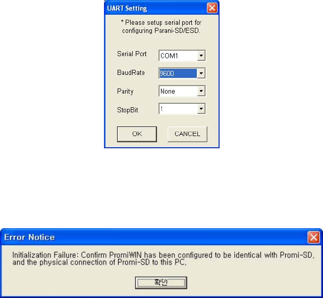
Figure 3-2 Serial Port Setting
Set each option properly and click [Confirm]. If the settings are different from the host computer, error
message will pop up. If the Parani-SD is in the status of connection, warning message will pop up.
Then the current connection can be cancelled by [Disconnect] button on the main window.
Figure 3-3 Error Message Box
15
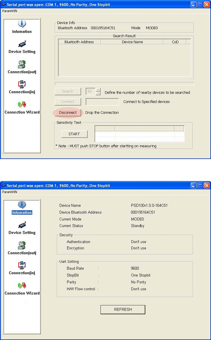
Figure 3-4 Main Window
Figure 3-5 Information Window
16
Serial port settings can be changed by <Start Configuration> and <ParaniWIN Configuration> of
ParaniWIN in the menu bar at upper left corner of the window without re-running the ParaniWIN
program.
Figure 3-6 Menu Bar at Upper Left corner of ParaniWIN
The icons in the left side window come to the corresponding windows.
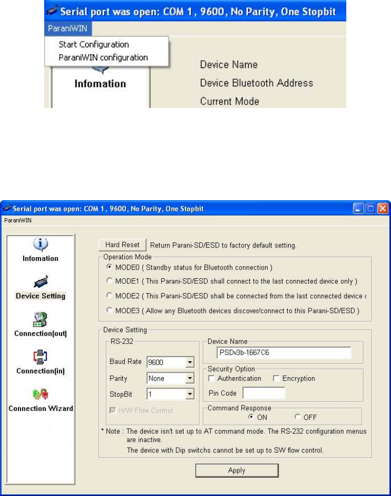
In device configuration window, hardware reset can be executed or operation mode and RS232 can
be configured as well. Security option also can be configured in this window.
Figure 3-7 Device Setting Window
Parani-SD supports two security options, Authentication and Encryption. If you check the
Authentication option, you must also enter the Pin Code value. If the authentication is activated, the
connection, only between the Master and Slave device that share the same Pin Code, is established.
In case that Parani-SD connects to other Bluetooth device that enables authentication, you must know
the other device’s Pin Code. In general Bluetooth devices, 1234 or 0000 is used as a default value. If
you check Encryption option, the Parani-SD encrypts packets and sends them. The Encryption options
works well in case that only one between Master and Slave uses this option.
17
Parani-SD has 4 response messages, ‘OK’, ‘ERROR’, ‘CONNECT’, and ‘DISCONNECT’. In some
cases, these responses can affect the host system unexpectedly. To prevent this, user can set the
Command response to ON or OFF.
For Parani-SD100L/200, hardware flow control can be configured only by dip switch. Thus H/W Flow
Control option will not work in this case. When the dipswitch value isn’t ATcommand mode, the RS-232
menu will be disabled.
Click [Apply] button to reflect the given options to Parani-SD actually.
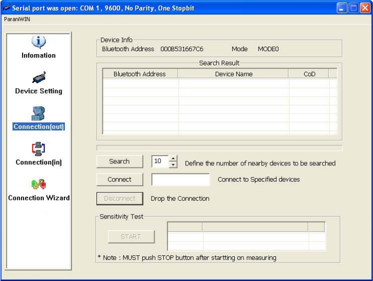
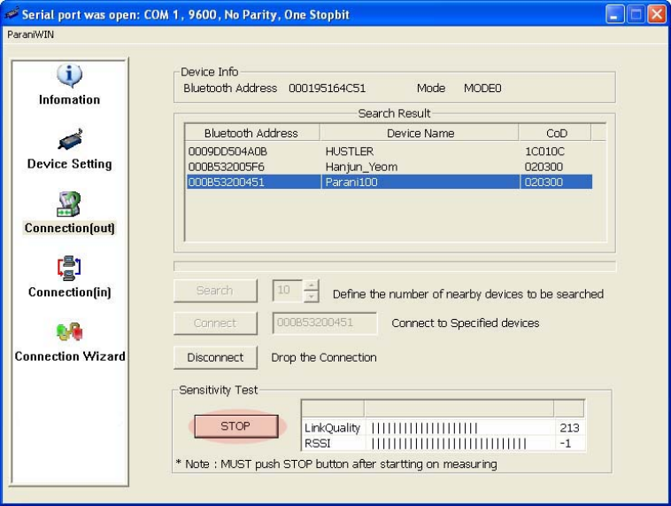
Connect(out) icon will show the following window to search and connect other Bluetooth devices.
Figure 3-8 Connect(out) Window
Click [Search] button to search nearby Bluetooth devices. The maximum number of devices to be
searched can be controlled. Select one of the devices searched and click [Connect] button. The
selected Bluetooth device must be in Page scan mode. Click [Disconnect] button to cancel the
connection normally.
After the connection is established, you are able to test sensitivity by pushing the START button.
18
Figure 3-9 Sensitivity Test
The sensitivity test shows LInkQuality and RSSI values. The sensitivity is fine, If the LinkQuality is
closer to 255 and RSSI is closer to 0. In general, the sensitivity is the best when the distance is 10
meters. You can push the STOP button in order to terminate the sensitivity test. The sensitivity test will
continue until the STOP button is pushed. If you close the ParaniWIN Window without pushing the
STOP button, you must restart Parani-SD to terminate the test.
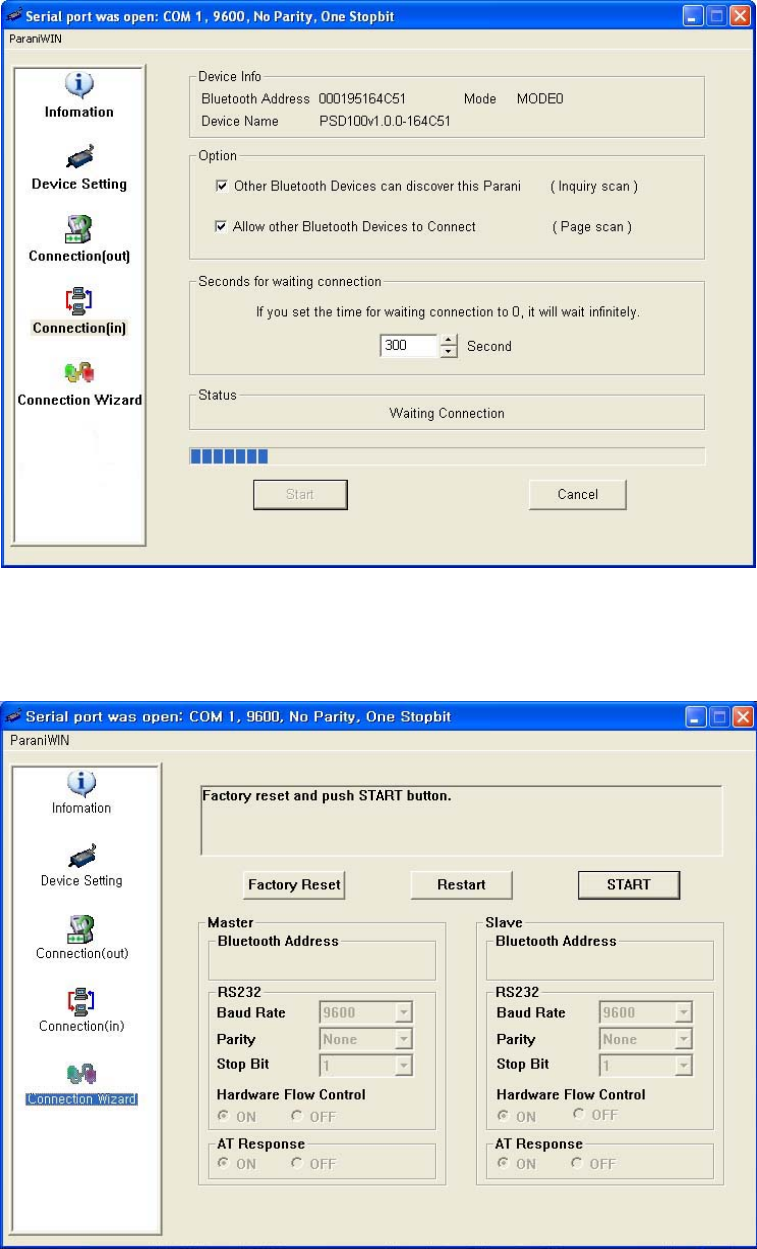
Connection(in) icon will show the following window to make Parani-SD wait to a connection from the
other Bluetooth device. The waiting time in seconds can be controlled. With 0 input for this waiting
time, Parani-SD keeps waiting for connection until [Cancel] button is clicked.
19
Figure 3-10 Connection(in) Window
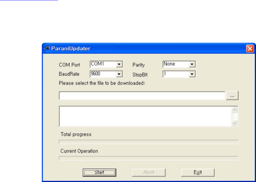
If the Connection Wizard icon is clicked, an easy pairing menu to use appears as follows:
Figure 3-11 Connection Wizard Window
20
This menu make easy pairing configuration of Parani-ESD that hasn’t pairing button. Although this
menu can be used to pairing configuration of Parani-SD that has pairing button, pairing configuration
by pairing button is recommended. To use this menu, follow next steps.
Step 1. Connect the first SD and then push the START button.
Step 2. Disconnect the first SD, connect the second ESD and then push the Next button after setting
up Slave configuration. At this time, the dip switch value should be ATcommand mode. The flow
control setting can be changed only through dip switch.
Step 3. Disconnect the second SD, once again connect the first ESD and then push the Finish button.
The pairing configuration finished. Make sure that each SD’s connect LED is on. From now, when
the SD restarts the pairing connection will be established automatically.
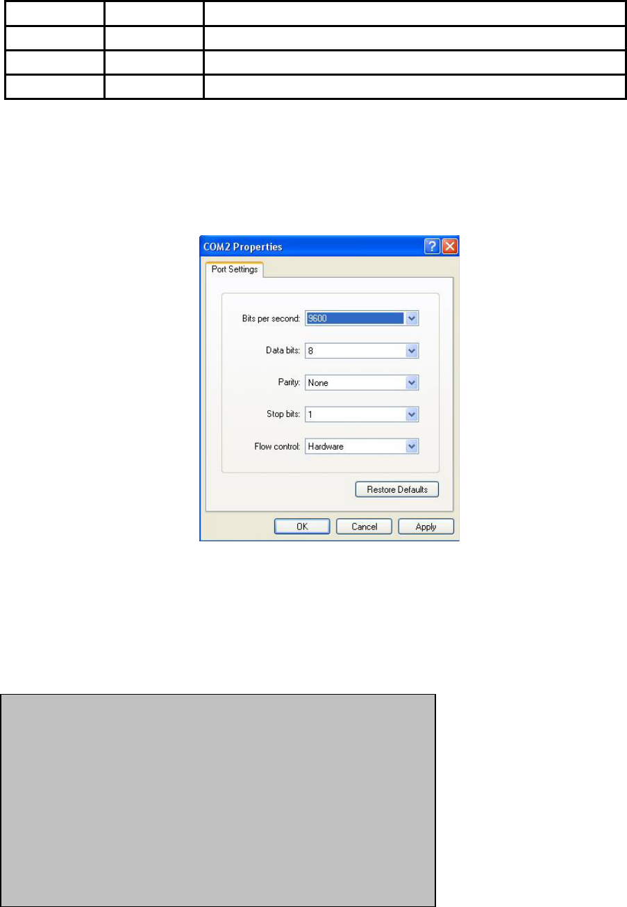
3.3.8. ParaniUpdater
Parani-SD support firmware update. You can download new firmwares of Parani-SD at
http://www.sena.com. With ParaniUpdater, you can update firmware of Parani-SD by selecting the
firmware image file and pushing Start button.
* Note: DO NOT power off Parani-SD while the firmware update is progressing. It may damage the
firmware seriously.
Figure 3-12 ParaniUpdater Window
.
3.3.9. Terminal Program
A terminal program is an application that will enable a PC to communicate directly with a modem. If
you are using Windows 98SE or higher version of Windows, HyperTerminal program as it is included
as part of the operating system. Parani-SD provides some extended AT commands for its
configurations on terminal program.
This manual will explain the method using HyperTerminal. If you need to install HyperTerminal, click
start>setting>control panel>add/remove programs. For more precise information, please refer to Help
of Microsoft Windows.
21
Attach Parani-SD to serial port of host computer and power on. Check Connect LED and Standby LED.
Their status may be as follows:
Table 3-8 Connect LED and Standby LED status
Connect LED Standby LED Meanings
On Off Connected to somewhere
Blinking Off Connecting to somewhere or waiting for incoming connection.
Off On Waiting for AT commands.
Launch HyperTerminal. It can be found in start >programs >accessories >communication
>HyperTerminal. Select the Serial port that Parani-SD will be connected to.
Input the same settings into Serial port configuration window as Parani-SD settings.
The settings need to be set correctly, otherwise, error message may be shown up on the screen or
cause malfunctioning of Parani-SD.
Figure 3-13 HyperTreminal
Choose the settings in File->Properties->Settings->ASCII setup that let you turn echo on in
HyperTerminal; this will show the response Parani-SD sends on the screen.
You now get the HyperTerminal window where you are able to control Parani-SD with AT commands.
For expanded AT commands that Parani-SD provides, please refer to Appendix A. AT commands.
Example of AT commands:
AT+BTINFO?
000B53000509,PSDv3b-000509,MODE0,STANDBY,0,0,HWFC
OK
AT+BTINQ?
000B5320007E,PSDv2a-20007E,001F00
0004B300E205,AP2002:1 #0,020300
OK
ATD000B53000509
OK
CONNECT 000B53000509
22
4. Approval Information
4.1. FCC
4.1.1. FCC Compliance Statement
This device complies with part 15 of the FCC Rules. Operation is subject to the following two
conditions:
(1) This device may not cause harmful interference, and
(2) This device must accept any interference received,
Including interference that may cause undesired operation
Information to User
This equipment has been tested and found to comply with the limits for a Class B digital device,
Pursuant to part 15 of the FCC Rules. These limits are designed to provide reasonable
protection against harmful interference in a residential installation.
This equipment generates, uses and can radiate radio Frequency energy and, if not installed
and used in accordance with the instructions, may cause harmful interference to radio
communications.
However, there is no guarantee that interference will not occur in a particular installation. If this
equipment does cause harmful interference to radio or television reception, which can be
determined by turning the equipment off and on, the user is encouraged to try to correct the
interference by one or more of the following measures:
- Reorient or relocate the receiving antenna.
- Increase the separation between the equipment and receiver- Connect the equipment into an
outlet on a circuit different from that to which the receiver is connected.
- Consult the dealer or an experienced radio/TV technician for help.
4.1.2. RF Exposure Statement
The equipment complies with FCC RF radiation exposure limits set forth for an uncontrolled
environment. This device and its antenna must not be co-located or operation in conjunction with
any other antenna or transmitter.
4.1.3. Do not
Any changes or modifications to the equipment not expressly approved by the party responsible for
compliance could void user’s authority to operate the equipment.
4.2. CE
4.2.1. EC-R&TTE Directive
EN 50385
EN 60950
EN 301 489-1/-17
EN 300 328

23
5. RF Information
5.1. Radio Frequency Range
2.402~2.480GHz
5.2. Number of Frequency Channel
79 channels
5.3. Transmission Method
FHSS(Frequency Hopping Spread Spectrum)
5.4. Modulation Method
GFSK(Gaussian-filtered Frequency Shift Keying)
5.5. Radio Output Power
Products Transmit Power
SD100L +18dBm
SD200L +2dBm
5.6. Receiving Sensitivity
Products Receive Sensitivity
SD100L -90dBm
SD200L -80dBm
5.7. Power Supply
Products Power Supply
SD100L DC5.0~12V / BAT 4.2V
SD200L DC5.0~12V / BAT 4.2V
24
Appendix A: Connections
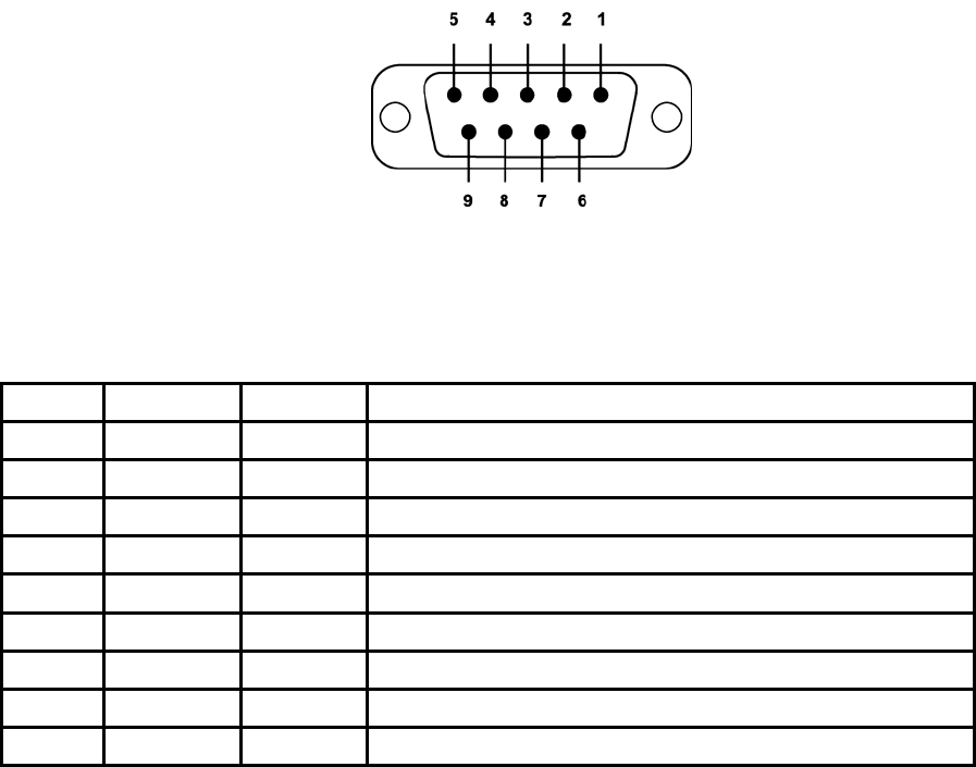
A.1. Serial Port Pin Outs
Parani-SD is a DCE device compatible with RS232 standard, having DB9 female interface.
Figure A-1 Pin layout of the DB-9 female connector
Table A-1. Pin assignment of the DB-9 female connector
Pin # Signal Direction Description
1 CD Output Received Line Signal Detect
2 TxD Output Transmitted Data
3 RxD Input Received Data
4 DSR Input DTE Ready
5 GND - Signal Ground
6 DTR Output DCE Ready
7 CTS Input Clear to Send
8 RTS Output Request to Send
9 Vcc Input Ring Indicator
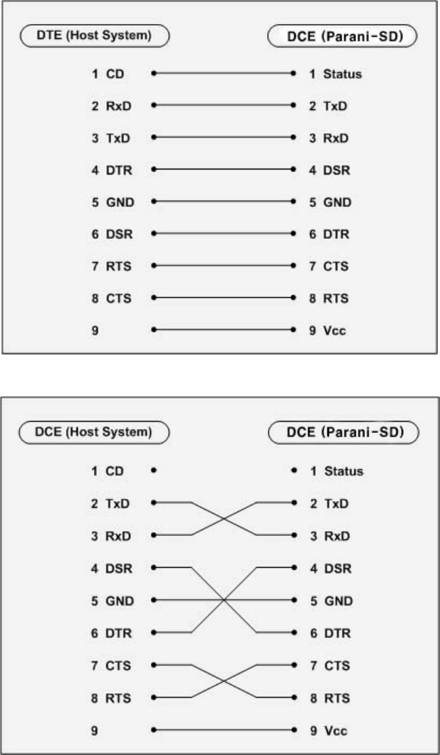
A.2. Serial Wiring Diagram
25
A.2.1. To Host with DTE Interface
A.2.2. To Host with DCE Interface

26
Appendix B: AT Commands
B.1. Terminology
B.1.1. AT Command
AT command set is the HTde facto standardTH HTlanguageTH for controlling HTmodemsTH. The AT command set was
developed by HTHayesTH and is recognized by virtually all HTpersonal computerTH modems. Parani-SD
provides the extended AT command set to control and configure the serial parameters and Bluetooth
connection.
B.1.1. AT Response
Parani-SD replies to AT commands with 4 kinds of message, ‘OK’, ‘ERROR’, ‘CONNECT’ and
‘DISCONNECT’.
B.1.2. Operation Mode
Mode Description
Mode0 Waiting for AT commands
Mode1 Attempting to connect the last connected Bluetooth device
Mode2 Waiting for the connection from the last connected Bluetooth device
Mode3 Waiting for the connection from any other Bluetooth device
B.1.3. Operation Status
Status Description
Standby Waiting for AT commands
Pending Executing tasks
Connect Executing tasks
B.1.4. Security
Security Description
Authentication Pin Code (or Pass key)
Encryption Data encryption

27
B.1.5. Symbols
The symbols are used for the description of command syntax as follows:
Symbols Meaning ASCII Code
Carriage return 0x0D
Line feed 0x0A
Carriage return + Line feed
Bluetooth device address
N or m One digit decimal number
to Timeout in seconds
B.2. Command Category
Command Category Index AT Commands
RESET 1
2 ATZ
AT&F
SERIAL PORT 3
4
5
AT
AT+UARTCONFIG,b,p,s
AT+USEDIP?
Information 6
7
8
AT+BTINFO?
AT+BTINQ?
AT+BTLAST
Mode 9 AT+BTMODEn
Status 10
11
12
13
14
15
16
+++
AT+SETESC,nn
ATO
AT+BTCANCEL
AT+BTSCAN
AT+BTSCAN,n,to
AT+BTSCAN112233445566,to
Connection 17
18
19
ATD
ATD112233445566
ATH
Security 20
21
22
23
24
AT+BTKEY=$string
AT+BTSD?
AT+BTCSD
AT+BTFP,n
AT+BTSEC,a,e
BLUETOOTH
Miscellaneous 25
26 AT+BTNAME=$string
AT+BTLPM,n
S-REGISTER 27
28
29
AT&V
ATSnn?
ATSnn=mm

28
B.3. Command Description
B.3.1. ATZ
SD Response OK
Purpose Software Reset
Description This is the same effect as power off and on.
This command disconnects Bluetooth device, and stops ongoing task. After rebooting, the
status is decided by the preset operation mode.
Some AT commands need ATZ to take effect.
Reference AT&F, AT+BTCSD, AT+UARTCONFIG
B.3.2. AT&F
SD Response OK
Purpose Hardware reset
Description This is the same effect as initialization by reset button.
All parameters are initialized to factory defaults. The storage of Parani-SD is cleared
completely.
Reference ATZ
B.3.3. AT
SD Response OK
Purpose Check the connection status with host equipment
Description Check if the connection to host equipment is normal. The serial parameters of Parani-SD
must be same as those of host equipment. If not, SD response is none or ‘ERROR’ or
abnormal sequence of strings.
Reference AT+UARTCONFIG, ATZ, AT&F
B.3.4. AT+UARTCONFIG,Baudrate,Parity,Stopbit
SD Response OK
Purpose Set Serial parameters
Parameters Baudrate=1200/2400/9600/14400/19200/38400/57600/115200/230400 (Default=9600)
Parity=N/E/O (Default=N)
Stopbit=1/2 (Default=1)
Description The Serial parameters can be set or changed. The factory default is 9600, N, 1.
To take effect of this command, ATZ or power off and on.
Reference AT, ATZ, AT&F, ATS
Example AT+UARTCONFIF,9600,N,1

29
B.3.5. AT+USEDIP?
SD Response m
Purpose Check the Baud rate set by dip switch
Description m=0: Set to ‘AT cmd’
m=1: Set to other than ‘AT cmd’
Reference AT, ATZ, AT&F, ATS
B.3.6. AT+BTINFO?
SD Response 112233445566,DeviceName,Mode,Status,Auth,Encryp,FlowControl
OK
Purpose Display Bluetooth settings
Description The current Bluetooth settings are displayed including BD address, Device name,
Operation mode, Operation status, Authentication, Data Encryption, and Hardware Flow
Control. The initial value of Device name is ‘PSD100Lv1.0.0-445566’. PSD stands for
Parani-SD, v1.0.0 for the version of firmware, and 445566 for the last 6 digits of BD
address.
Mode=MODE0/MODE1/MODE2/MODE3
Status=STANDBY/PENDING/CONNECT
Auth=0/1 (Authentication is not activated when 0)
Encrypt=0/1 (Encryption is not activated when 0)
FlowControl=HWFC/NoFC
Reference AT+BTNAME, AT+BTMODE, AT+BTSEC, ATS14?
Example 000B530011FF,SENA,MODE0,PENDING,1,1,HWFC
B.3.7. AT+BTINQ?
SD Response 112233445566,FriendlyName,CoD
112233445566,FriendlyName,CoD
112233445566,FriendlyName,CoD
OK
Purpose Search Bluetooth devices nearby
Description The Bluetooth devices in Inquiry scan mode nearby are displayed with their BD addresses,
Device names, and Class of device.
Maximum 10 devices are scanned for 30 seconds.
Reference AT+BTSCAN, ATD, AT+BTINFO?
B.3.8. AT+BTLAST?
SD Response 112233445566
Purpose Display the BD address of the last connected device
Description The Bluetooth device connected to this Parani-SD last time is displayed with its BD
address.

30
Reference AT+BTSCAN, ATD, AT+BTINFO?, AT+BTINQ?
B.3.9. AT+BTVER?
SD Response SD100Lv1.0.0
OK
Purpose Display device firmware version
Description Display device firmware version
Reference AT+BTINFO?
B.3.10. AT+BTRSSI,n
SD Response OK
0,255,0,0 (repeatedly)
Purpose Test sensitivity
Parameters n=0: Start sensitivity test
n=1: Stop sensitivity test
Description When Bluetooth connection is established, you can use this command in Stanby status.
The sensitivity will be displayed repeatedly in order of Status, LinkQuality, Status, RSSI. If
the LinkQuality is close to 255 and RSSI is close to 0, the sensitivity is not bad.
Example +++
AT+BTRSSI,1
OK
0,255,0,0
B.3.11. AT+BTMODE,n
SD Response OK
Purpose Set operation mode
Parameters n=0: MODE0 (Default)
n=1: MODE1
n=2: MODE2
n=3: MODE3
Description When the operation status is ‘Pending’ currently, change the status to ‘Standby’ with
AT+BTCANCEL prior to this command.
To take effect of this command, ATZ or power off and on
Reference AT+BTINFO?
Example AT+BTMODE,2
OK
ATZ
B.3.12. +++

31
SD Response OK
Purpose Convert the operation status of ‘Connect’ to ‘Standby’
Description In ‘Connect’ status, data from host is transmitted to the other side Bluetooth device, and
any AT command is not accepted but this command, which is not echoed on the screen.
When Parani-SD encounters a character ‘+’ from host, it stops the data transmission and
waits for next 2 characters. If the next 2 characters aren’t both ‘+’, it restart to transmit data
including the first ‘+’ as well. If not, it converts the operation status to ‘Standby’.
If the data from host includes ‘+++’, it will convert the operation status to ‘Standby’
unexpectedly. Notice that Parani-SD holds data transmission when it encounters ‘+’, until
receiving next character.
‘+’ is an escape sequence character by default, which is changeable by AT+SETESC.
Reference AT+SETESC, ATO, AT+BTCANCEL
B.3.13. AT+SETESC,nn
SD Response OK
Purpose Change the escape sequence character
Description Escape sequence character set to ‘+’ by default is changeable.
The parameter nn must be a printable character.
Reference +++, ATO
Example AT+SETESC,42
B.3.14. ATO
SD Response None
Purpose Convert the operation status of ‘Standby’ to ‘Connect’
Description You can convert the operation status of ‘Standby’ to ‘Connect’ ready to transmit data.
Reference +++, AT+SETESC
B.3.15. AT+BTCANCEL
SD Response OK
Purpose Terminate a current executing task
Description This terminates a current executing task, such as Inquiry scan and Page scan, then
converts the operation status to ‘Standby’
Reference AT+BTSCAN, ATD, AT+BTINQ?
B.3.16. AT+BTSCAN
SD Response OK
CONNECT 112233445566
Purpose Wait for inquiry and connection from other Bluetooth devices

32
Description This allows the inquiry and connection from the other Bluetooth devices. The operation
status will be in ‘Pending’ after this command. When connection is made and released, the
operation status is back to ‘Pending’. To convert the operation status to ‘Standby’
AT+BTCANCEL must be used.
This has the same effect as AT+BTSCAN,3,0.
When connection is made with other Bluetooth device, SD response will be ‘CONNECT’
with its BD address.
Reference ATD, AT+BTINQ?, AT+BTCANCEL
B.3.17. AT+BTSCAN,n,to
SD Response OK
CONNECT 112233445566
or
OK
ERROR
Purpose Wait for inquiry and connection from other Bluetooth devices for a given duration
Parameters n=1: Allows Inquiry scan
n=2: Allows Page scan
n=3: Allows both of Inquiry scan and Page scan
to= Time duration in seconds
Description For the given to, Parani-SD is waiting for the inquiry and connection from other Bluetooth
devices. If the parameter of to is 0, it will wait forever.
When connection is made with other Bluetooth device, SD response will be ‘CONNECT’
with its BD address. If there is no connection made within this time duration, SD response
is ‘ERROR’ and the operation status becomes to ‘Standby’.
Reference ATD, AT+BTINQ?, AT+BTCANCEL
Example AT+BTSCAN,2,30
B.3.18. AT+BTSCAN112233445566,to
SD Response OK
CONNECT 112233445566
or
OK
ERROR
Purpose Wait for connection by the Bluetooth device with given BD address
Parameters 112233445566=BD address
to= time duration in seconds
Description For the given to, Parani-SD is waiting for the connection from the Bluetooth device with the
given BD address. If the parameter of to is 0, it will wait forever.
When connection is made with the Bluetooth device, SD response will be ‘CONNECT’ with
its BD address. If there is no connection made within this time duration, SD response is
‘ERROR’ and the operation status becomes to ‘Standby’.
Reference ATD, AT+BTINQ?, AT+BTCANCEL
Example AT+BTSCAN000B530011FF,30
B.3.19. ATD

33
SD Response OK
CONNECT 112233445566
or
OK
ERROR
Purpose Connect to the last connected Bluetooth device
Description Parani-SD saves the BD address of the Bluetooth device most recently connected. ATD
can make connection to it without input its BD address.
If it fails to make connection, SD response is ‘ERROR’.
Reference AT+BTINQ?, AT+BTSCAN
B.3.20. ATD112233445566
SD Response OK
CONNECT 112233445566
or
OK
ERROR
Purpose Connect to the Bluetooth device with given BD address
Parameters 112233445566=BD address
Description Parani-SD attempts to connect to the Bluetooth device with the given BD address. To make
successful connection, the Bluetooth device must be in Page scan. This attempt continues
for 5 minutes.
If it fails to make connection, SD response is ‘ERROR’.
Reference AT+BTINQ?, AT+BTSCAN
Example ATD000B530011FF
B.3.21. ATH
SD Response OK
DISCONNECT
Purpose Release the current connection
Description The current Bluetooth connection is released normally. It takes about 30 seconds to detect
an abnormal disconnection such as power off and moving out of service range.
Reference ATD, AT+BTSCAN
B.3.22. AT+BTKEY=$string
SD Response OK
Purpose Change pin code
Parameters $string= New pin code (Default=”1234”)
Description Pin code is a string, which allows 16 alpha-numeric characters maximum. Based on this pin
code, Parani-SD generates a link key which is used in actual authentication process
Reference AT+BTCSD, AT+BTFP, AT+BTSD?, AT+BTSEC, ATZ, AT&F

34
Example AT+BTKEY=”apple”
B.3.23. AT+BTSD?
SD Response 112233445566
OK
Purpose Display the list of Bluetooth devices sharing the pin code
Description Once a connection is made with pin code, Parani-SD saves the Bluetooth device with its
link key generated by pin code. The connection to a device listed in Parani-SD can be
made automatically without authentication process. The maximum number of the list is 5.
Reference AT+BTCSD, AT+BTFP, AT+BTKEY, AT+BTSEC, ATZ, AT&F
B.3.24. AT+BTCSD
SD Response OK
Purpose Clear the list of Bluetooth devices sharing the pin code
Description This clears the list of Bluetooth devices with link key in flash memory. To take effect of this
command, ATZ or power off and on because the main memory still has the list.
Reference AT+BTFP, AT+BTKEY, AT+BTSD?, AT+BTSEC, ATZ, AT&F
B.3.25. AT+BTFP,n
SD Response OK
Purpose Set generation of link key every time of connection
Parameters n=0: Inactivate (Default)
n=1: Activate
Description If n is set to 1, Parani-SD asks pin code every time of connection. This is used to level up
the security.
Reference AT+BTCSD, AT+BTKEY, AT+BTSD?, AT+BTSEC, ATD, ATZ, AT&F
B.3.26. AT+BTSEC,Authentication,Encryption
SD Response OK
Purpose Set authentication and data encryption
Parameters Authentication=0: Inactivate (Default)
Authentication=1: Activate
Encryption=0: Inactivate (Default)
Encryption=1: Activate
Description If the authentication is activated, the pin code must be set by AT+BTKEY command. Data
encryption cannot be used when authentication is not activated, i.e. Authentication=0 and
Encryption=1 is not valid.
Reference AT+BTCSD, AT+BTFP, AT+BTSD?, AT+BTSD?, ATZ, AT&F

35
B.3.27. AT+BTNAME=$string
SD Response OK
Purpose Change device name
Parameters $string= New device name (Default=”PSDv3b-445566”)
Description Parani-SD can have a user friendly name to identify easily. The name allows 30 alpha-
numeric characters maximum.
Reference AT+BTINFO?, AT+BTINQ?
Example AT+BTNAME=”My-Parani-SD”
B.3.28. AT+BTLPM,n
SD Response OK
Purpose Set low power mode
Parameters n=0: Inactivate (Default)
n=1: Activate
Description During no data transmission, Parani-SD can be in low power mode to save the power
consumption. It takes a few seconds to wake up Parani-SD in low power mode.
B.3.29. AT+DFU
SD Response (Display garbage messages repeatedly)
Purpose Device firmware update
Description DO NOT use this command in console. Because the Parani-SD enter into firmware update
mode, garbage messages will appear. This command is used by ParaniWIN’s firmware
update menu.
B.3.30. AT&V
SD Response S0:m0;S1:m1; …Sn:mn
OK
Purpose Display all the S-register
Description All parameters are stored at S-register in flash memory. These values are sustained until
hardware reset.
Reference ATS
B.3.31. ATSnn?
SD Response value
OK

36
Purpose Display a given S-register
Parameters nn= Address of S-register
Description A specific S-register is displayed.
Reference AT&V
B.3.32. ATSnn=mm
SD Response OK
Purpose Change S-register value
Parameters nn= Address of S-register
mm= New value of S-register
Description Some S-registers are optimized for the overall performance and protected from an arbitrary
change by user. When users try to change these S-registers, SD response is ‘ERROR’.
For details of S-register, refer Appendix. B.
Reference AT&V
Example ATS10=0
B.4. Command Validity
Operation Status AT Command
Standby Pending Connect
AT ○ ○
ATZ ○ ○
AT&F ○ ○
AT+BINQ? ◎
ATD112233445566 ◎
ATD ◎
AT+BTSCAN ◎
AT+BTSCAN,n,to ◎
AT+BTSCAN112233445566,to ◎
AT+BTCANCEL
○
+++
○
AT+SETESC ◎
ATO ●
ATH ●
AT+BTSEC,Auth,Encr ◎
AT+BTLAST? ○ ○

37
AT+BTMODEn ◎
AT+BTNAME=”Name” ◎
AT+BTKEY=”nnnn” ◎
AT+BTINFO? ○
AT+BTLPM,n ◎
AT+BTSD? ○ ○
AT+BTCSD ◎
AT+BTFP,n ◎
AT+UARTCONFIG,b,p,s ◎
AT+USEDIP? ○ ○
AT+BTVER? ○ ○
AT+DFU ◎ ◎
AT+BTRSSI,n ●
◎ Valid only when Parani-SD is not connected to other Bluetooth device.
● Valid only when Parani-SD is connected to other Bluetooth device.
38
Appendix C: S-Register
S-registers contain 46 parameters of Parani-SD. These are stored in flash memory and sustained the
values unless hardware reset is executed. The value of S-register can be accessed and changed with
ATS command by user. Some S-registers not shown below are set to maximize the performance of
Parani-SD. Thus it is not recommended to change these S-registers.
Change the value of S-register only in Standby status.
C.1. S1: Force to Reconnect (default 1)
S1=0, Parani-SD in Mode1 does not try reconnection when disconnected.
S1=1, Parani-SD in Mode1 keeps trying reconnection when disconnected.
C.2. S2: Enable Hardware Flow Control (default 1)
S2=0, Parani-SD’s hardware flow control is off.
S2=1, Parani-SD’s hardware flow control is on.
In case of SD Series, it can be changed only through dip switch.
C.3. S3: Stream UART Policy (default 0)
S3=0, the priority of UART streaming is throughput.
S3=1, the priority is latency, which minimizes the delay of data transmission. This is useful in case of
transmiting very small data quickly.
This value decides the way of handling stream data from UART. When this value is 1, in order that SD
minimizes the latency, SD sends the received data immediately. When this value is 0, in order that SD
maximizes throughput, SD stores received data for a short time and sends a large packet. If the
packet length is less than100 bytes, latency-oriented way is better. But if the packet length is more
than 100 bytes, throughput-oriented way is recommended. Also if you want to use high baudrate,
throughput-oriented way is more effective. Just for reference, the buffer length for receiving is 2 Kbytes.
C.4. S4: Enable Remote Name Query (default 1)
S4=0, Parani-SD inquires only BD address. This speeds up the inquiry process.
S4=1, Parani-SD inquire BD address, device name and class of device.
This value decides whether SD finds friendly name of Bluetooth device or not. When this value is 1,
SD finds not only BD address but also friendly name. When this value is 0, SD finds only BD address.
Without finding friendly name, a searching is quick to respond. If you want to search the other
Bluetooth devices quickly, set this value to 0. In case of using pairing button, finding friendly name will
be omitted automatically.
39
C.5. S6: Enable Low Power Mode (default 0)
S10=0, deactivate Low Power Mode.
S10=1, activate Low Power Mode.
This value decides whether SD works in Low Power Mode or not. When this value is 0, SD works only
in active power mode. When SD works in Low Power mode, delay in transferring data may occur.
C.6. S10: Enable SD Response (default 1)
S10=0, Parani-SD does not send SD responses to host system.
S10=1, Parani-SD send SD responses to host system.
This value decides whether SD sends response messages such as OK, ERROR, CONNECT,
DISCONNECT or not. When this value is 0, SD sends no response messages. If the response
messages cause troubles in host programs or devices that is connected to SD, change this value to 0.
C.7. S11: Enable Escape (default 1)
S11=0, Parani-SD does not allow escape sequence character. The operation status of Connect cannot
be changed to Standby. As Parani-SD skips the process detecting escape sequence character, the
more efficient data transmission is expected.
S11=1, Parani-SD allow escape sequence character. Whenever it is needed, the Connect status can
be changed to Standby.
C.8. S12: Clear Data Buffer When Disconnected (default 0)
S12=0, Parani-SD does not clear the data buffer received from host system when disconnected.
S12=1, Parani-SD clears the data buffer when disconnected.
C.9. S14: Enable DTR Transfer (default 1)
S14=0, DTR/DSR signal is transferred to loop-back.
S14=1, DTR signal is transferred to DSR of remote device.
C.10. S15: Enable Disconnect by DTR (default 0)
S15=0, DTR signal cannot release the connection.
S15=1, The Bluetooth connection can be released when DTR signal is off.
This value decides whether Bluetooth connection is released when DTR signal drops or not. If this
value is 1, you can use DTR signal in order to disconnect Bluetooth connection.
C.11. S22: Fast Connect (default 0)
S22=0, none
S22=1, page scan
S22=2, inquiry scan
40
S22=3, page/inquiry scan
C.12. S24: Maximum Number of Inquiry Result (default 10)
The maximum number of inquiry list can be controlled. This value is up to 15,
C.13. S28: Escape Sequence Character (default 43)
The decimal number of the ASCII code of escape sequence character can be controlled. The initial
value is 43, the ASCII code of ‘+’.
C.14. S31: Page Timeout (default 300)
This is the timeout in seconds to attempt connection with ATD command. After this timeout expires, the
SD will restart automatically. If this value is 0, SD will attempt to connect without restarting
C.15. S33: Inquiry Timeout (default 30)
This is the timeout in seconds to execute inquiry scan.
C.16. S37: Supervision Timeout (default 16000)
This is the timeout in 625µsec to presume disconnection, which is set to 16000 initially.
16000¯625µsec=10sec)
The smaller the value becomes, the more quickly Parani-SD can detect an abnormal disconnection.
But when the communication is suspended for some environmental reasons, it may be regarded as
disconnection.
C.17. S46: BD Address of Last Connected Device
This saves the BD address of the Bluetooth device connected most recently.
41
Appendix D: Trouble Shooting
D.1 No Data Transmission
D.1.1 COM Port Settings
Check whether the Baud rate of Parani-SD is same as that of its host equipment. You can know the
Baud Rare if you check the dipswitch. If it is Atcommand mode, you can initialize Baud rate to 9600 by
pressing Reset Button.
Check whether the Data bit is set to 8. Parani-SD supports only 8 Data bit. If your host equipment
uses 7 Data bit and even or odd parity, it can work as if it uses 8 Data bit and No parity. This is valid
only when both DCE devices are Parani-SD. In this case, set both Parani-SDs to 8 Data bit and No
parity. If one of DCE devices is other Bluetooth device such as Bluetooth USB dongle, please contact
Technical Support.
Check whether the Parity and Stop bit of Parani-SD are same as those of its host equipment. Parani-
SD supports No parity, Even parity and Odd parity, 1 and 2 Stop bit.
Check whether the host equipment of Parani-SD uses Hardware Flow Control. Parani-SD is initially
set to Use of Hardware Flow Control. If your host equipment does not use Hardware Flow Control, set
the Hardware Flow Control of Parani-SD to No use. The Hardware Flow Control can be changed only
by dipswitch.
Parani-SD does not support RS-232 break signal.
D.1.2 Pin Assignment
Parani-SD is DCE device. If your host equipment is DTE, plug Parani-SD directly to the host
equipment or use straight RS-232 cable. If your host equipment is DCE, use cross over RS-232 cable
(Null modem cable).
D.2 Data Loss or Malfunctioning
D.2.1Hardware Flow Control
When transmitting large data with No use of Hardware Flow Control, Parani-SD will clear the data
buffer unexpectedly. This possibility goes higher as the RF transmission environment is bad.
D.2.2 AT Response
42
The messages of AT response may affect the function of host system. Set ATS10=0 not to send SD
response to host system and try again. Refer Appendix B. for details.
D.3 Transmission Delay
D.3.1 RF Processing Delay
It takes 30msec approximately for a Parani-SD to complete the data transmission to the other side
Bluetooth device. This time delay cannot be reduced and would be bigger as the RF transmission
environment is bad. Do not use Parani-SD If your applications cannot allow this time delay.
D.3.2 RF Transmission Environment
If there are lots of Bluetooth device working in a small area and/or the RF communication distance is
too long and/or there are some obstacles affecting RF performance, Parani-SD repeats the
transmission packet by packet due to interferences and/or low RF performance. This leads the
transmission time delay.