SENTRY SPBPT Bluetooth Module User Manual Manual
Sentry Industries limited Bluetooth Module Manual
SENTRY >
Manual

SENTRY
AC410x family + BT
-V2.0
User’s Manual

SENTRY
AC410x family+BT-V2.0
User’s Manual
3/14/2014
1
TABLE OF CONTENTS
1. INTRODUCTION AND BLOCK DIAGRAM........................................................................................... 2
1.1. GENERAL INTRODUCTION ....................................................................................................................... 2
1.2. BLOCK D
IAGRAM
.................................................................................................................................... 3
2. MAIN FEATURES AND APPLICATION.................................................................................................. 4
2.1. SYSTEM KEY F
EATURE
............................................................................................................................ 4
2.2. APPLICATION........................................................................................................................................... 4
3. TECHNICAL SPECIFICATIONS.............................................................................................................. 5
3.1. AC410X FAMILY CHARACTERISTICS ....................................................................................................... 5
3.2. BT-V2.0 BLUETOOTH MODULE
C
HARACTERISTICS
................................................................................ 7
4. BT-V2.0 BLUETOOTH MODULE MECHANICAL DIMENSIONS AND ELECTRICAL FEATURE
8
4.1. BT-V2.0 SCHEMATIC............................................................................................................................... 8
4.2. BT-V2.0 PIN A
SSIGNMENT
...................................................................................................................... 8
4.3. BT-V2.0
OUTLINE
:(
MM
) .......................................................................................................................... 9
4.4. BT-V2.0 PCB LOCATION ...................................................................................................................... 10
5. RECOMMENDED REFLOW TEMPERATURE PROFILE................................................................. 12
6. RELATED RECOMMENDED ................................................................................................................. 13
7. DOCUMENT HISTORY ........................................................................................................................... 14

SENTRY
AC410x family+BT-V2.0
User’s Manual
3/14/2014
2
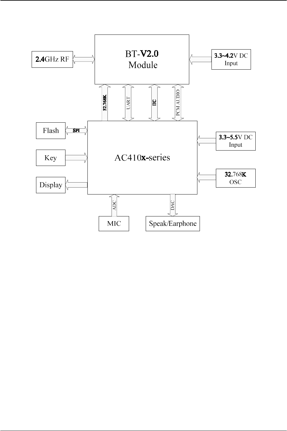
1. Introduction and Block Diagram
1.1. General Introduction
BT-V2.0(BK3513) is a Bluetooth 2.1 class 2 modules which is a high performance, cost
effective, low power and compact solution. The Bluetooth class 2 module provides a complete
2.4GHz Bluetooth system based on BK3513 chip which is a single chip radio and baseband
IC for Bluetooth 2.4GHz systems. This module is fully compliant to Bluetooth v2.1 for audio
communications.
The AC410x family is a low-power, high-performance microprocessor with 96KB SRAM,
which incorporates a 32-bit RISC CPU, a high-speed digital signal processor(DSP) and rich
peripheral circuits. Key features of the AC410x family include:
---- 36 Programmable GPIO.
---- Support Watch Dog (WDT) and RTC.
---- 24 Interrupt Sources and 4 interrupt priority level.
---- Support idle/standby/sleep low power mode and IO wakeup.
---- Two 8bit and two 16bit Timer/Counters, supports PWM mode and capture function.
---- 16bit stereo DAC with Headphone Amplifier.
---- 16bit ADC with Microphone Amplifier.
---- Two full-duplex UART, and UART0 supports DMA.
---- Two SPI controller supports master and slave, and DMA.
---- Two SD master controller supports DMA.
---- One full speed USB2.0 controller which supports master and slave.
---- One IIC and one IIS controller.
The AC410x family is a powerful microprocessor with rich peripheral resources which
provides a highly flexible and cost effective solution to many embedded control applications.
SENTRY
AC410x family+BT-V2.0
User’s Manual
3/14/2014
3
1.2. Block Diagram

SENTRY
AC410x family+BT-V2.0
User’s Manual
3/14/2014
4
2. Main Features and Application
2.1. System Key Feature
● Bluetooth Class2 operation (up to 10 meters range).
● Mono codec with 1 microphone inputs.
● Radio includes integrated balun 5-band fully configurable EQ.
● compliant with the Bluetooth V2.1 protocol.
● support the Bluetooth protocol framework:
HANDS-FREE PROFILE (HFP:HF);
ADVANCED AUDIO DISTRIBUTION PROFILE(A2DP:SNK);
AUDIO/VIDEO REMOTE CONTROL PROFILE(AVRCP:CT);
● support the SBC decoding, support for stereo output with 16KHz/32KHz/44.1KHz/48KHz
sample rate
● support the mobile music player switching songs, playing or pausing music
● support the echo cancellation and noise suppression
● support incoming call answer / reject, voice reporting calling number, adjusting the volume
●support active connections and simple pairing;
2.2. Application
● Mono headsets
● Wired Mono headsets and headphones
● Wireless telephone and stereo headphones
● Portable speakers
● Mp3 player and PMP
● Car Audio
● Other portable devices
SENTRY
AC410x family+BT-V2.0
User’s Manual
3/14/2014
5
3. Technical Specifications
3.1. AC410x family Characteristics
3.1.1 General Specification
Number Items Description
1 MCU 32-bit RISC CPU
2 Chipset AC410x family
3 Packaging LQFP64,LQFP48,QFN32,SOP28,SSOP24
4 Voltage 3V3~5V5
5 Temperature -20~+80 ℃
6 Storage Temperature -40~+85 ℃
3.1.2 Electrical Characteristics
AC410x family Item Min Typ Max Unit Note
State Working voltage +3.3 +4.2V +5.5V V
Working current
--
28mA
-- mA
Standby current -- 100uA -- uA
Power supply:+4.2V
Call and music
3.1.3 Mono Codec: Analogue to Digital Converter
Analogue to Digital Converter
Parameter Conditions Min Typ Max Note
Resolution -- -- 16 Bits
Input Sample
Rate,FSAMPLE 8 -- 48 kHz
SNR
fin=1kHz
B/W=20Hz-Fsample/2
(20kHz max)
A-Weighted
THD+N<0.1%
FSAMPLE
8kHz -- 87 -- dB
16kHz -- 87 -- dB
32kHz -- 87 -- dB
44.1kHz -- 87 -- dB
2.0Vpk-pk input 48kHz -- 87 -- dB
AC410x family+BT-V2.0
User’s Manual
3/14/2014
6
THD +N
fin=1kHz
B/W=20Hz- Fsample/2
(20kHz max)
FSAMPLE
8kHz -- 0.08 -- %
Analogue Gain
2.0Vpk-pk input 48kHz -- 0.08 -- %
Analogue setting = 12dB to54dB in
1.5dB steps 12 -- 54 dB
Mono separation (crosstalk) -- -80 -- dB
3.1.4 Mono Codec: Digital to Analogue Converter
Analogue to Digital Converter
Parameter Conditions Min Typ Max Note
Resolution --- -- -- 16 Bits
Output Sample
Rate,FSAMPLE -- 8 -- 96 kHz
SNR
fin=1kHz
B/W=20Hz-20kHz
A-Weighted
THD+N<0.1%
FSAMPLE Load
48kHz 100kΩ -- 87 -- dB
48kHz 32kΩ -- 87 -- dB
0dBFS input 48kHz 16kΩ -- 87 -- dB
FSAMPLE
Load
8kHz 100kΩ -- 0.0035 -- %
THD+N
fin=1kHz
B/W=20Hz-20kHz
0dBFS input
8kHz 32kΩ -- 0.05 -- %
8kHz 16kΩ -- 0.1 -- %
48kHz 100kΩ -- 0.0035 -- %
48kHz 32kΩ -- 0.05 -- %
48kHz 16kΩ -- 0.1 -- %
Analogue Gain Analogue Gain Resolution = 3dB -42
--
0 dB
Mono separation (crosstalk) -- -80 -- dB
3.1.5 Auxiliary ADC
Auxiliary ADC Min Typ Max Unit
Resolution -- 16 -- Bits
Input voltage range(a) -- 3.0 -- V
Accuracy
(Guaranteed monotonic)
INL -1 -- 1 LSB
DNL 0 -- 1 LSB

AC410x family+BT-V2.0
User’s Manual
3/14/2014
7
Offset -1 -- 1 LSB
Gain error -1 -- 1 %
Input bandwidth -- 41.5 -- kHz
Conversion time -- 14 -- µs
Sample rate(b) -- -- 83k Samples/s
(a)LSB size = VDD_AUX/1023
(b)The auxiliary ADC is accessed through a VM function. The sample rate given is achieved as
part of this function.
3.2. BT-V2.0 Bluetooth Module Characteristics
3.2.1 General Specification
Number Items Description
1 Bluetooth Standard Bluetooth v2.1 Standard
2 Chipset BK3513
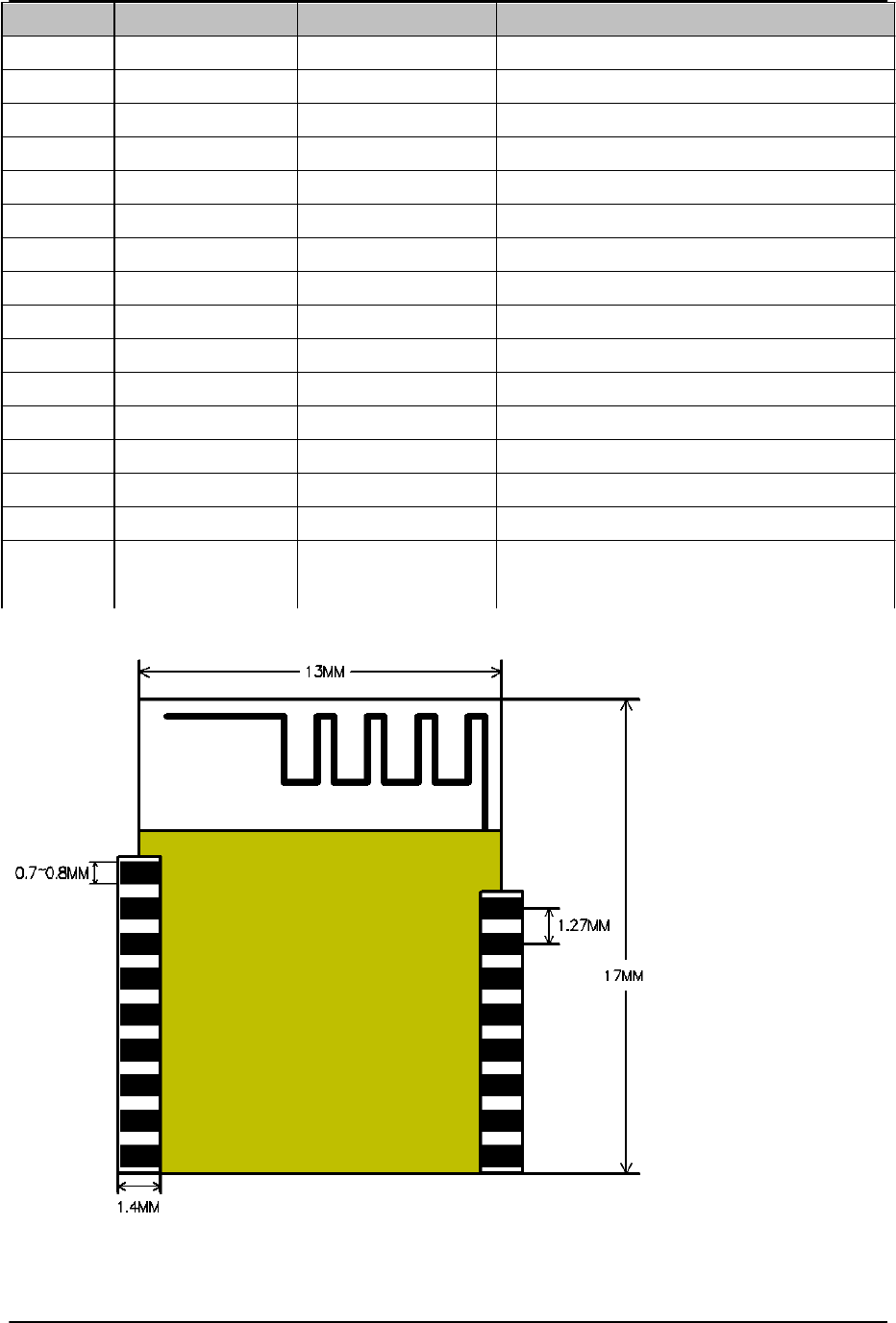
3 Dimension 17mm x 13mm x 2mm
4 Voltage 3V3~4V2
5 Temperature -20~+60 ℃
6 Storage Temperature -40~+85 ℃
7 Frequency Range 2402~2480MHz
8 Maximum RF Transmit Power 8dBm
9 Receive Sensitivity -85dBm
10 Bluetooth® Profile Supported A2DP,AVRCP,HFP
3.2 .2 Power Consumption
BT-V2.0 Item Min Typ Max Unit Note
State Working voltage +3.3V +3.3V +4.2V V
Working current 28mA mA
Standby current
150uA
uA
Power supply:+3.3V
Call and music
AC410x family+BT-V2.0
User’s Manual
3/14/2014
8
4. BT-V2.0 Bluetooth Module Mechanical
Dimensions and Electrical feature
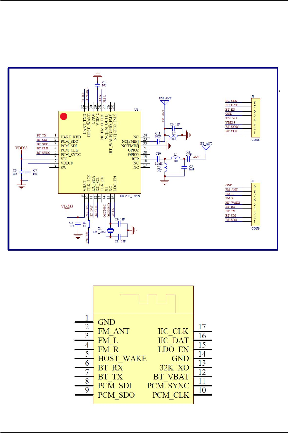
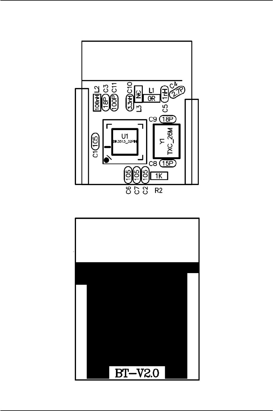
4.1. BT-V2.0 Schematic
4.2. BT-V2.0 Pin Assignment
AC410x family+BT-V2.0
User’s Manual
3/14/2014
9
Pin No. Name Functions Description
1 GND VSS GND
2 FM-ANT FM ANT
3 FM-L Analog FM left-channel Output
4 FM-R Analog FM right-channel Output
5 HOST-WAKE Output To wakeup host. Output to host.
6 BT-RX Input UART RX data input
7 BT-TX Output UART TX data output
8 PCM-SDI Input PCM data input
9 PCM-SDO Output PCM data output
10 PCM-CLK Input PCM data clk
11 PCM-SYNC Input PCM data sync
12 BT-VBAT Power Power supply input
13 32K-XO Input 32.768 kHz clock input
14 GND VSS Power GND
15 LDO-EN Input Request source clock active
16 IIC-DAT Input/Output I2C Data signal
17 IIC-CLK Input I2C Clock signal
4.3. BT-V2.0 outline:(mm)
AC410x family+BT-V2.0
User’s Manual
3/14/2014
10
4.4. BT-V2.0 PCB Location
Top Location:
Bottom Location:
AC410x family+BT-V2.0
User’s Manual
3/14/2014
12
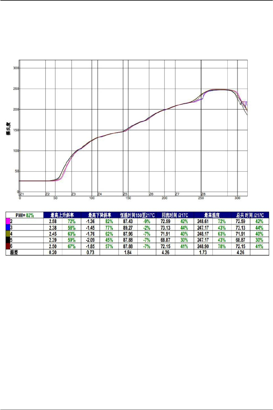
5. Recommended Reflow Temperature Profile
The module must go through 125℃ baking for at least 9 hours before SMT AND
IRreflow process.

AC410x family+BT-V2.0
User’s Manual
3/14/2014
13
6. Related recommended
● If you want to use the MIC function, in order to achieve the best sound effects,
please don't take MICAnd SPK is placed in the same plane, preferably vertically
placed
● Full metal shell will greatly shorten the Bluetooth transmission distance
● Bluetooth antenna below PCB plate not copper

AC410x family+BT-V2.0
User’s Manual
3/14/2014
14
7. Document History
Revision Date History
V1.0 2014.12.17
V1.1 2014.03.14 Delete the Application Reference Design

AC410x family+BT-V2.0
User’s Manual
3/14/2014
14
FCC Statement:
This equipment has been tested and found to comply with the limits for Part 15 of the FCC rules.
These limits are designed to provide reasonable protection against harmful interference in a
residential installation. This equipment generates, uses and can radiate radio frequency energy and,
if not installed and used in accordance with the instructions, may cause harmful interference to radio
communications.
However, there is no guarantee that interference will not occur in a particular installation. If this
equipment does cause harmful interference to radio or television reception, which can be
determined by turning the equipment off and on, the user is encouraged to try to correct the
interference by one or more of the following measures:
• Reorient or relocate the receiving antenna.
• Increase the separation between the equipment and receiver.
• Connect the equipment to an outlet on a circuit different from that to which the receiver
is connected.
This device complies with part 15 of the FCC rules. Operation is subject to the following two
conditions: (1) This device may not cause harmful interference, and (2) this device must accept any
interference received, including interference that may cause undesired operation.
Note: Modifications to this product will void the user’s authority to operate this equipment.
RF Radiation Exposure Statement:
1.This Transmitter must not be co‐located or operating in conjunction with any other antenna or
transmitter.
2.This equipment complies with FCC RF radiation exposure limits set forth for an uncontrolled
environment. This equipment should be installed and operated with a minimum distance of 20
centimeters between the radiator and your body.
FCC Information to OEM integrator
The OEM integrator has to be aware not to provide information to the end user regarding how to
install or remove this RF module in the user manual of the end product.
The user manual which is provided by OEM integrators for end users must include the following
information in a prominent location.
1.To comply with FCC RF exposure compliance requirements, the antenna used for this transmitter
must be installed to provide a separation distance of at least 20 cm from all persons and must not
be co ‐located or operating in conjunction with any other antenna or transmitter, except in
accordance with FCC multi‐transmitter product procedures.
2. Only those antennas with same type and lesser gain filed under this FCC ID number can be used
with this device.
3. The regulatory label on the final system must include the statement: “Contains FCC ID: 2ACP4-
SPBPT or using electronic labeling method as documented in KDB 784748.
4. The final system integrator must ensure there is no instruction provided in the user manual or
customer documentation indicating how to install or remove the transmitter module except such
device has implemented two‐ways authentication between module and the host system