SEOWON INTECH SWC-2100 VoIP CPE WIMAX User Manual Microsoft PowerPoint SWC 2100 User Guide
SEOWON INTECH CO., LTD. VoIP CPE WIMAX Microsoft PowerPoint SWC 2100 User Guide
Users Manual
SEOWON INTECH
SWC-2100(VoIP CPE)
User Guide

Contents
1. VoIP CPE Overview
1.1 Product Introduction ------------------------------------------------- 4
1.2 Packaging Contents ------------------------------------------------- 5
1.3 Description of Product Functions ---------------------------------- 6
1.4 Network Configuration ----------------------------------------------- 8
2. VoIP CPE Connection
2.1 WiMAX Wired Connection (CPE) --------------------------------- 10
2.2 WiMAX Wired PHONE Connection ----------------------------- 11
3. PC Configuration
3.1 Windows 98/ME Setup ---------------------------------------------- 13
3.2 Windows 2000 Setup ------------------------------------------------ 17
3.3 Windows XP Setup --------------------------------------------------- 21
4. VoIP CPE built-in Web Server Access
4.1 Web Server Access ---------------------------------------------------- 26
5. VoIP CPE WiMAX Setup
5.1. IP Address Setup ---------------------------------------------------- 27
5.2 WIMAX Modem Setup ---------------------------------------------- 28
6. VoIP CPE Setup
6.1 VoIP Setting ----------------------------------------------------------- 29

7. VoIP CPE LAN Setup
7.1 DHCP Server Setup ------------------------------------------------ 30
7.2 MAC Address Setup ------------------------------------------------ 31
7.3 LAN Status Information ------------------------------------------- 32
8. Application Support Setup
8.1 Firewall Setup ----------------------------------------------------- 33
8.2 Port Forwarding --------------------------------------------------- 34
8.3 VPN Pass through Setup ----------------------------------------- 35
9. Administrator Function Setup
9.1 Administrator Time Setup ---------------------------------------- 36
9.2 Administrator Password Setup ----------------------------------- 37
9.3 Firmware Upgrade ------------------------------------------------ 38
9.4 Administration Rebooting ---------------------------------------- 39
10.References
10.1 LAN CABLE Standard Materials ------------------------------ 40
10.2 IP Router PING Test Method ------------------------------------ 41
10.3 Product Specifications -------------------------------------------- 42
10.4 Troubleshooting(Actions to be taken when internet is disconnected) --
43
10.5 Product Warranty and Customer Support --------------------- 45

1. VoIP CPE Configuration and Connection
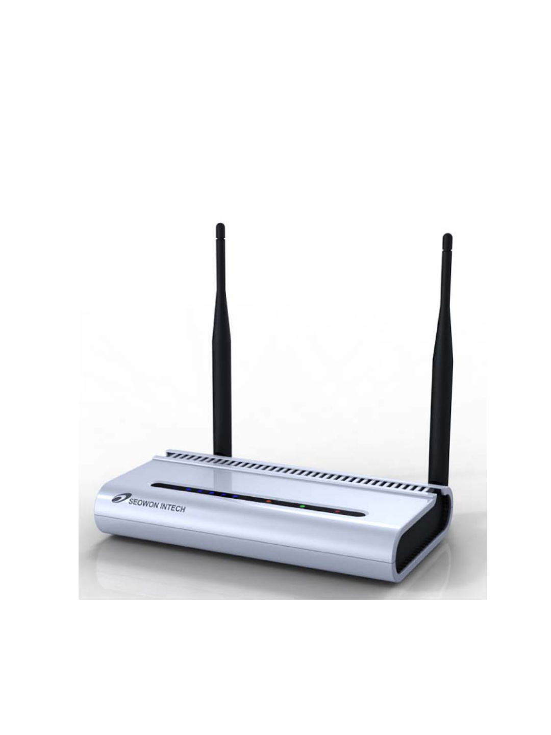
1.1 Product Introduction
This product receives external WiMAX signals to construct in-building infrastructure on WiMAX
network and is covered by Ethernet network internally. The product serves as a relay as well as a
USB Modem and an internet router.
But the product is purposed to supply to users, focusing on a relay part rather than a modem.
It is also a wired and wireless internet router which allows several systems to use one internet
address supplied by high-speed internet service provider.
◎Functional Features
Function Features
IEEE802.16e WiMAX
Support Wave1 = DL : 10Mbps / UL : 4Mbps
IEEE802.3u Ethernet Support 10/100Mbps wired LAN connectable
RJ-11 VoIP Support 1 x RJ-11 for Analog Telephone Service
LAN Port 1 Port 10/100Mbps Ethernet Switch built-in
Cable Auto Sense Straight (Direct) or Cross Cable auto sensing
NAT function Possible of max. 253 wired and connections and internet router*
Firewall function Manages basic firewall and IP/Port/based access
4
5
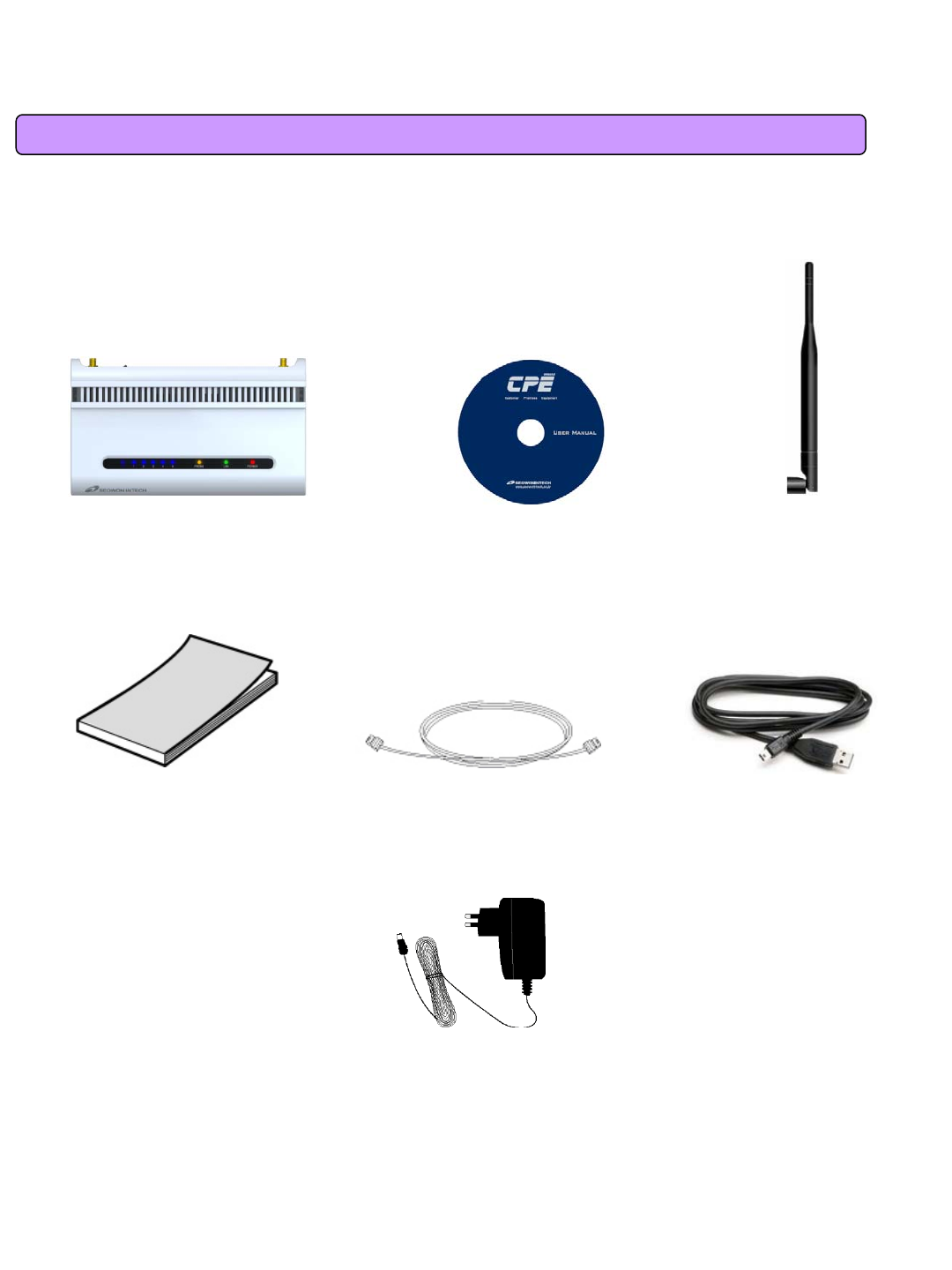
1.2 Packaging Contents
<Figure: Main Unit> <Figure: CD> <Figure: Antenna X 2>
<Figure: Quick Guide> <Figure: UTP Cable> <Figure: USB Cable>
<Figure: Adapter>
6
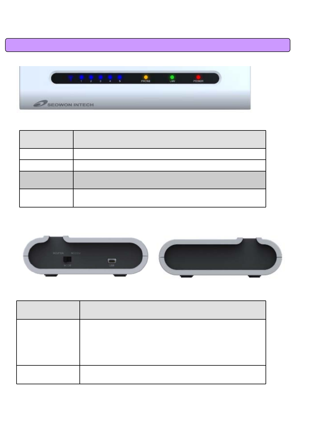
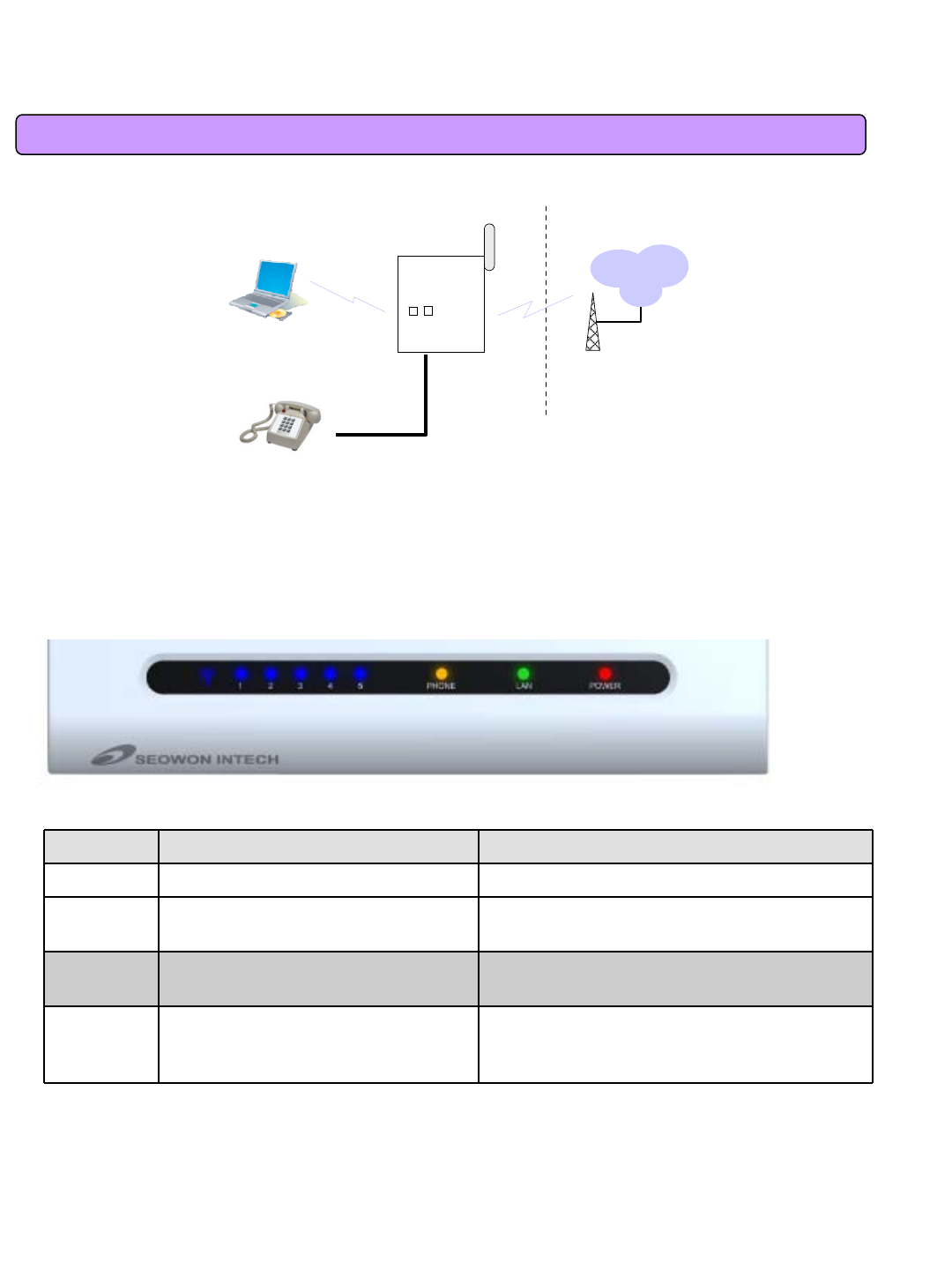
1.3 Description of Product Functions
<Figure: VoIP CPE Front LED part>
LED Indicator Function
PWR Power Supply status (On at Power ON)
LAN ON when connected to PC, Flashing at communication
PHONE ON when connected to Telephone, Flashing at communication
RSSI Representation WiMAX received signal strength indication(RSSI), on
when the mode was selected router.
<VoIP CPE Lateral side>
Description
Item Details
Mode Switch
-Router
-Modem
: Default Setting; Main function Mode;
Mode for WiMAX, general router function
: WiMAX Modem dedicated Mode; If VoIP CPE has no Power, you
can use WiMAX Modem function by using the USB power of
external PC.
USB Uses external PC power; Port used when using WiMAX Modem’s
sole function
SEOWONINTECH
7
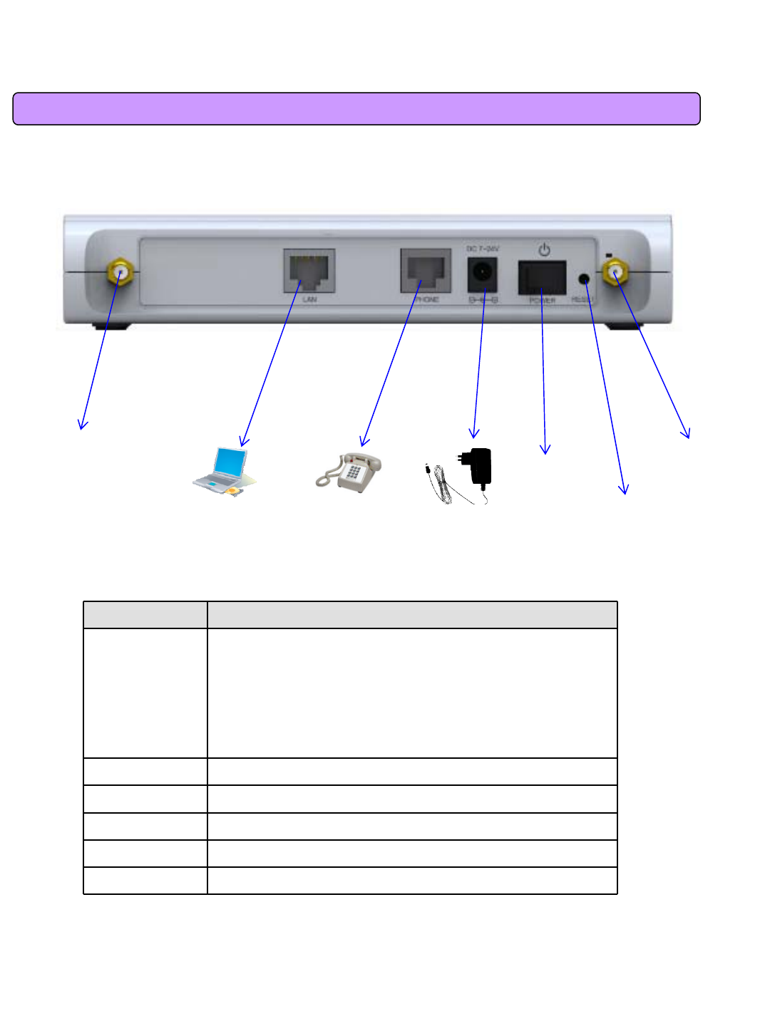
1.3 Description of Product Functions(Cont’)
VoIP CPE Rear Side
Description
Item Details
External
Antenna ANT1: WiMAX Diversity
ANT2: WiMAX Main
Separable external antenna
User external type antenna attachable
* Antenna Classification
-3: 2.3GHz
-5: 2.5GHz
Power S/W Power On/Off Switch (On/Off by pressing right or left)
DC IN Power Adapter connection (DC12V)
PHONE Telephone connection
LAN PC or Hub connection
Factory Reset Restore the VoIP CPE Factory Default
[Note] If you lost LOGIN password for router or IP address after change, use the Reset switch to restore its
original Factory Default settings.
WiMAX
Diversity
Antenna
WiMAX
Main
Antenna
Power
Switch
Hardware
Reset
PC Tele Phone Power Adapter
8
1.4 Network Configuration
PC
Gateway
Internet
Local Network External Network
WiMAX
<VoIP CPE Connection Example>
LED Normal Operation Actions to be taken at failure
PWR ON when connecting adapter Check for adapter power failure
LAN ON when cable is connected
normally Check cable connection and PC power supply
PHONE On when Phone cable is connected
normally Check cable connection and Telephone
WiMAX
RSSI
Representation WiMAX received
signal strength indication(RSSI), on
when the mode was selected router. Check the mode selected router
SEOWONINTECH
To Verify normal operation of router LEDs
You have to check if each LED of the router operates properly after connecting router, modem, and PC
with LAN cable as follows:.
Telephone

9
1.4 Network Configuration
If LED light is not in “normal operation”, check if there is any failure according to actions to be taken.
Install a router after connecting to network.
„If normal connection between router and PC is checked, you have to set up PC and router.
„PC setup is to control network option such as Win98/2000/XP to enable to use Internet on condition that
PC is connected to router. It is progressed by referring to Chapter II, depending on OS type.
Router setup is to connect a router to Internet, which is suitable for the Internet line type that is connected
to router. It is progressed by referring to Chapter III, depending on Internet type.
10
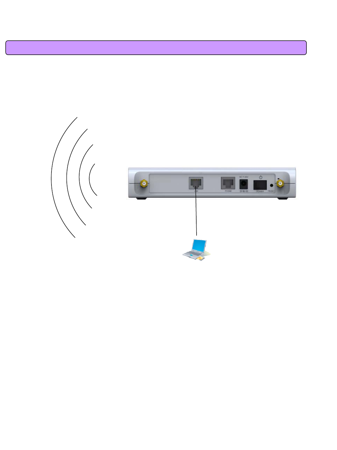
2.1 WiMAX Wired LAN Connection (CPE)
2. VoIP CPE Connection
PC
WiMAX
11
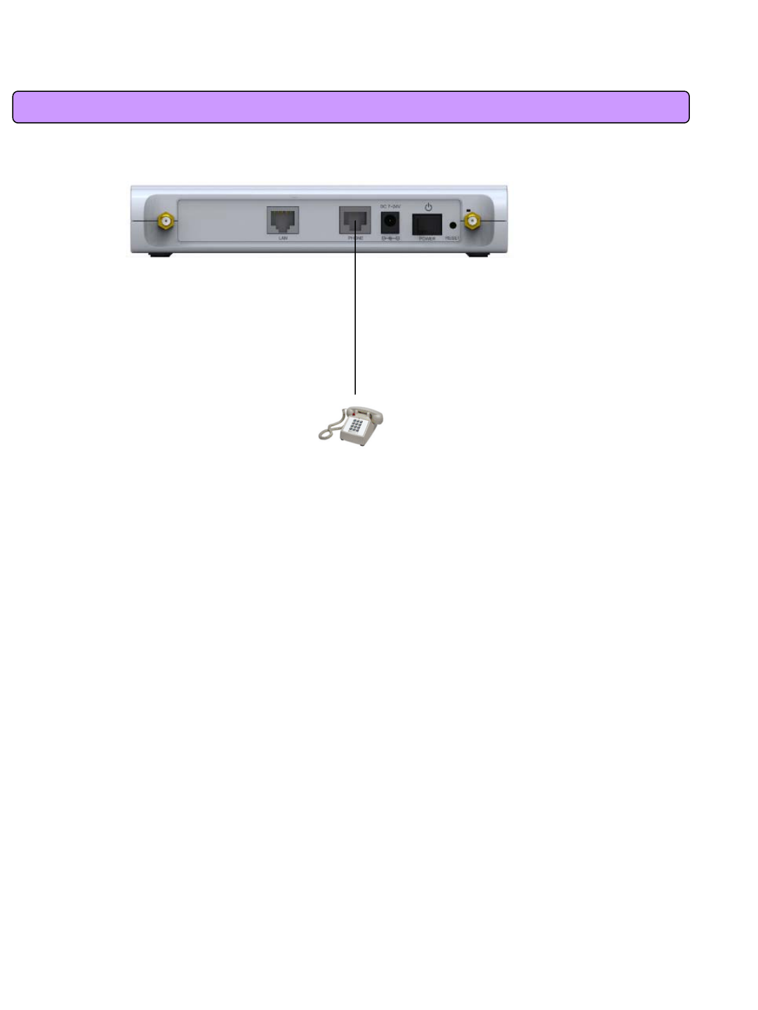
2.2 WiMAX Wired PHONE Connection
Telephone

12
3. PC Configuration
This chapter describes how to set up PC network environment by connecting to VoIP CPE according to
Windows operating system.
To use Internet under operating system such as Windows, the protocol called ‘TCP/IP’is required.
For normal use of VoIP CPE, you have to set up the TCP/IP protocol normally.
In general, the condition Windows is installed first in PC is the condition router can be used, in which no
separate TCP/IP setup is required.
13
3.1 Windows 98/ME Setup
This procedure is to restore your Windows 98/ME TCP/IP settings to default values. If Windows is installed
in your PC for the first time, there is no change and check if all values are normal as the following:
After completing the TCP/IP setup of your PC, connect PC and VoIP CPE with a LAN cable according to the
instructions of Chapter 2 (STEP II) and turn the VoIP CPE on before Windows setup in order to check if IP
address is being given automatically in the VoIP CPE.
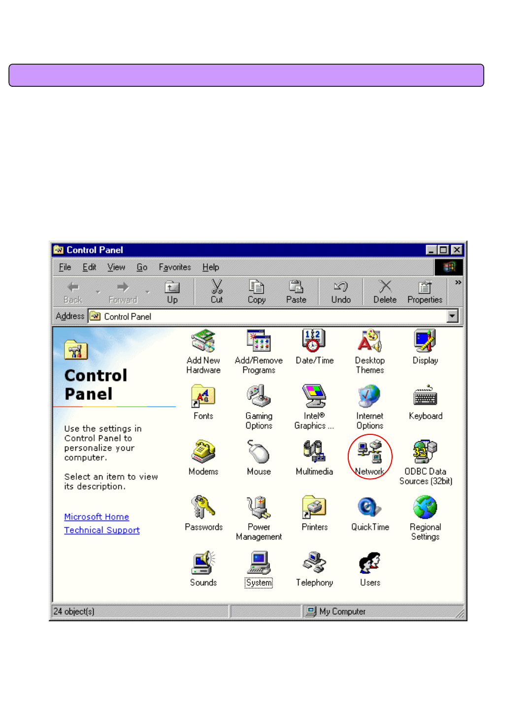
Click the Windows Start button and select Settings >> Control Panel on the menu.
Double-click the Network icon on the Control Panel window.
<Select Network Icon>
14
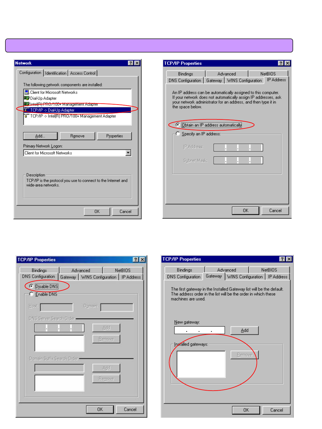
3.1 Windows 98/ME Setup
< Select TCP/IP > < Select Obtain an IP address automatically >
- Remove all gateways installed in Gateway. …
-Choose “Disable DNS”from DNS Configuration.
<Chosse ‘Disable DNS’> <Remove all Gateway items>
15
3.1 Windows 98/ME Setup
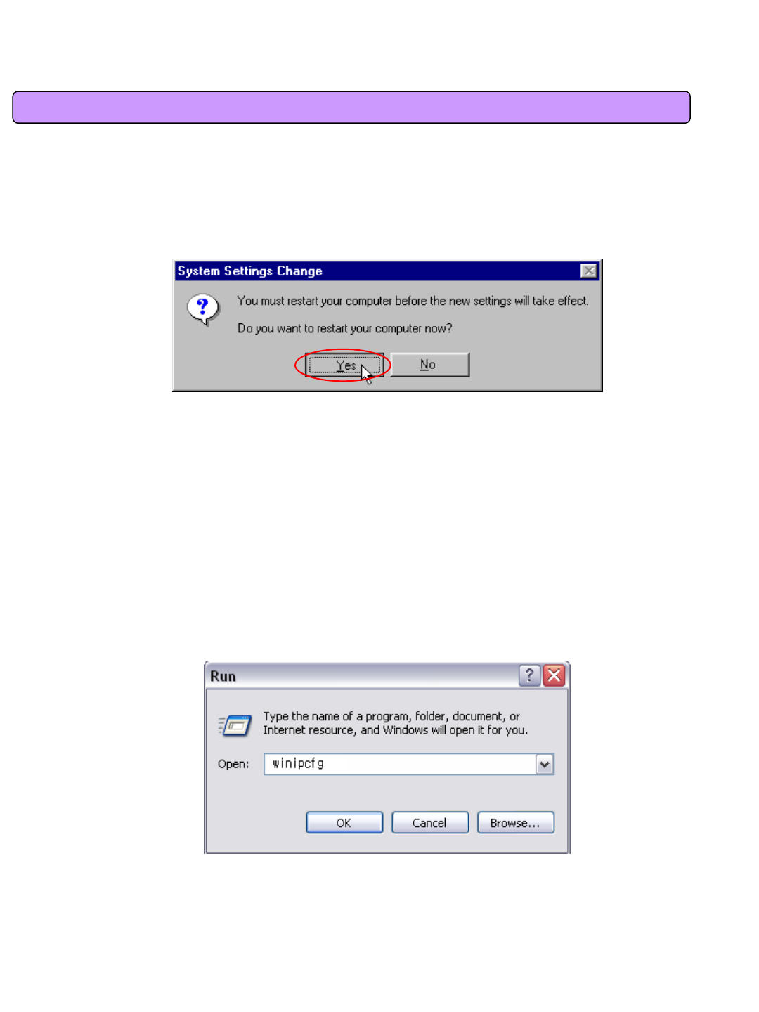
- When IP Address, Gateway, DNS Configuration setups are completed, click on ‘OK’to close the TCP/IP
Properties dialog box. When “Network”window is displayed, click ‘OK’again.
- In case of Windows 98, the system restarts automatically when network related setup is changed.
When the ‘Change System Setup’screen pops up, click ‘Yes’to restart Windows.
<Confirm System Restarting>
<Run winipcfg >
- When the PC is restarted, VoIP CPE assigns the IP address automatically.
For automatic assignment, PC and VoIP CPE should be connected by LAN cable.
If cable is not connected, connect a cable and then restart the PC.
- For automatic assignment of IP address, you can check it by using winipcfg program.
Click the Windows Start button, and then select Run menu and enter “winipcfg”in the
Open box, and click on ‘OK’button.
16
3.1 Windows 98/ME Setup
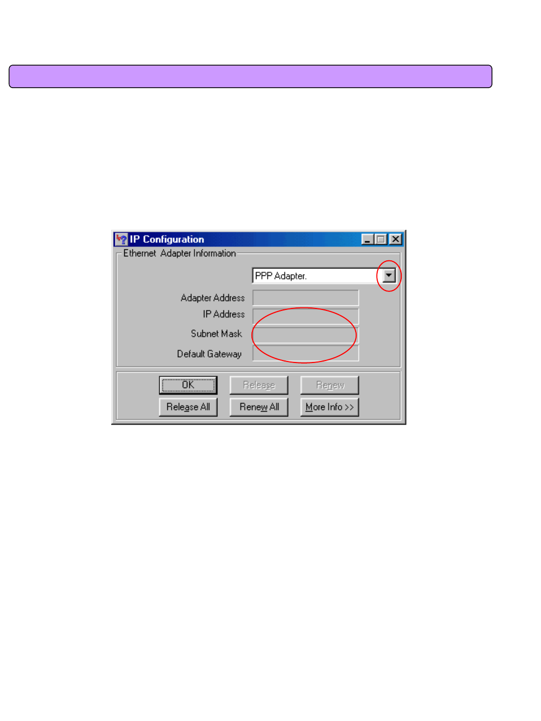
Select LAN card adapter used by connecting the router from the winipcfg IP Configuration window (Select NDIS
5.0 or the appropriate LAN card. Do not select PPP adapter) to check if the IP address of your PC is assigned to
the value between 192.168.1.10 and 192.168.1.150 automatically. If you cannot see other LAN card than PPP
adapter being used, you have to reinstall a LAN card driver. (Select LAN Card, click “Disconnect”and then “All
Create”or “All Update”button to check IP assignment.)
[Note] All PCs connected to VoIP CPE will get each of assigned IP addresses respectively.
00-52-00-01-19-A2
192.168.1.10
255.255.255.0
192.168.1.1
Select
Select LAN Card: Select NDIS 5.0 or the appropriate LAN card
Adapter Address: Different values on each adapter, ignorable
IP Address: 192.168.1.100 ~ 192.168.1.150
Subnet Mask: 255.255.255.0
Default Gateway: 192.168.1.1
[Note] If the IP address of PC is not assigned automatically, check the following and restart PC to check if the IP
address is assigned.
- Connect a LAN cable between PC and VoIP CPE
- Check TCP/IP setup details
To use Internet after completion of PC setup, refer to Chapter IV and set the WAN port of VoIP CPE to connect to
the Internet. Since Internet connection setup is made by VoIP CPE, you don’t need to set up in all PCs but do just
once.
< Check IP Address >
17
3.2 Windows 2000 Setup
This procedure is to restore Windows 2000’s TCP/IP setup to default values. If Windows is not
installed for the first time in PC or Internet is not operated properly, check all values are normal
according to the following.
After completing the TCP/IP setup of PC, to check if IP address is obtained from VoIP CPE
automatically, connect PC and VoIP CPE with a LAN cable according to the instructions of
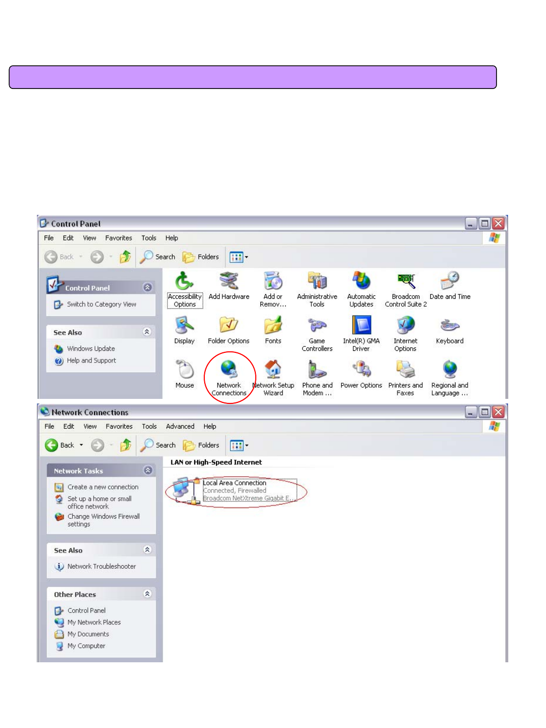
Chapter II and keep VoIP CPE turned on before Windows setting up. Click on the Windows Start
button, select Settings >> Control Panel on the menu and then double-click the “Network
Connections”icon.
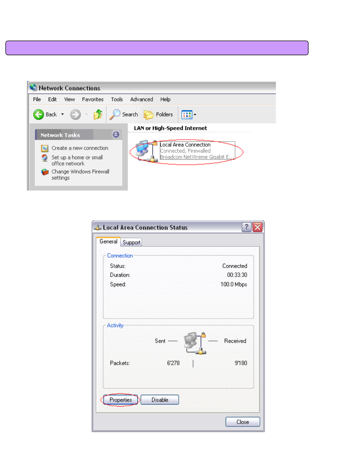
<Double-click the Local Area Connection >
- Click Properties from the Local Area Connection window.
- Double-click Internet Protocol (TCP/IP) from the Properties window.
18
3.2 Windows 2000 Setup
<Double-click TCP/IP>
- After completion of setup, click OK button and close all of Network Connections windows.
- When TCP/IP setup is completed, IP address is automatically assigned by VoIP CPE. For automatic assignment,
PC and VoIP CPE should be connected with a LAN cable. If it is not connected with a cable, connect the cable and
restart the PC.
<Select “Obtain an IP address automatically”“Obtain
DNS server address automatically”and click OK>
19
3.2 Windows 2000 Setup
- You can check the automatic IP address assignment by using the ipconfig command from Command Prompt.
- To run the Command Prompt, click the Start button on the lower left corner of Windows screen and click Run to
enter “cmd”in the Open box, and then click OK button.
When the Command Prompt runs, enter the “ipconfig”command to verify IP address, Subnet mask, and Gateway,
which are automatically assigned to PC.
[Note] All PCs connected to VoIP CPE will get each of assigned IP addresses respectively.
<Run cmd>
20
3.2 Windows 2000 Setup
IP Address: 192.168.1.100~150
Subnet Mask: 255.255.255.0
Default Gateway: 192.168.1.1
[Note] If IP address is not assigned normally, check the following and restart PC so as to check if the IP
address is assigned.
- LAN cable connection between PC and VoIP CPE
- Check TCP/IP setup details
- Whether or not to remove ADSL access program
To use Internet after completion of PC setup, refer to Chapter IV and set the WiMAX of VoIP CPE to connect
to the Internet. Since Internet connection setup is made by router, you don’t need to set up in all PCs but
do just once.
<Verify IP address>
21
3.3 Windows XP Setup
This procedure is to restore Windows XP’s TCP/IP setup to default values. If Windows is installed
for the first time in PC, there is no change and check all values are normal according to the
following.
After completing the TCP/IP setup of PC, to check if IP address is obtained from VoIP CPE
automatically, connect PC and VoIP CPE with a LAN cable according to the instructions of Chapter 2
and keep VoIP CPE turned on before Windows setting up.
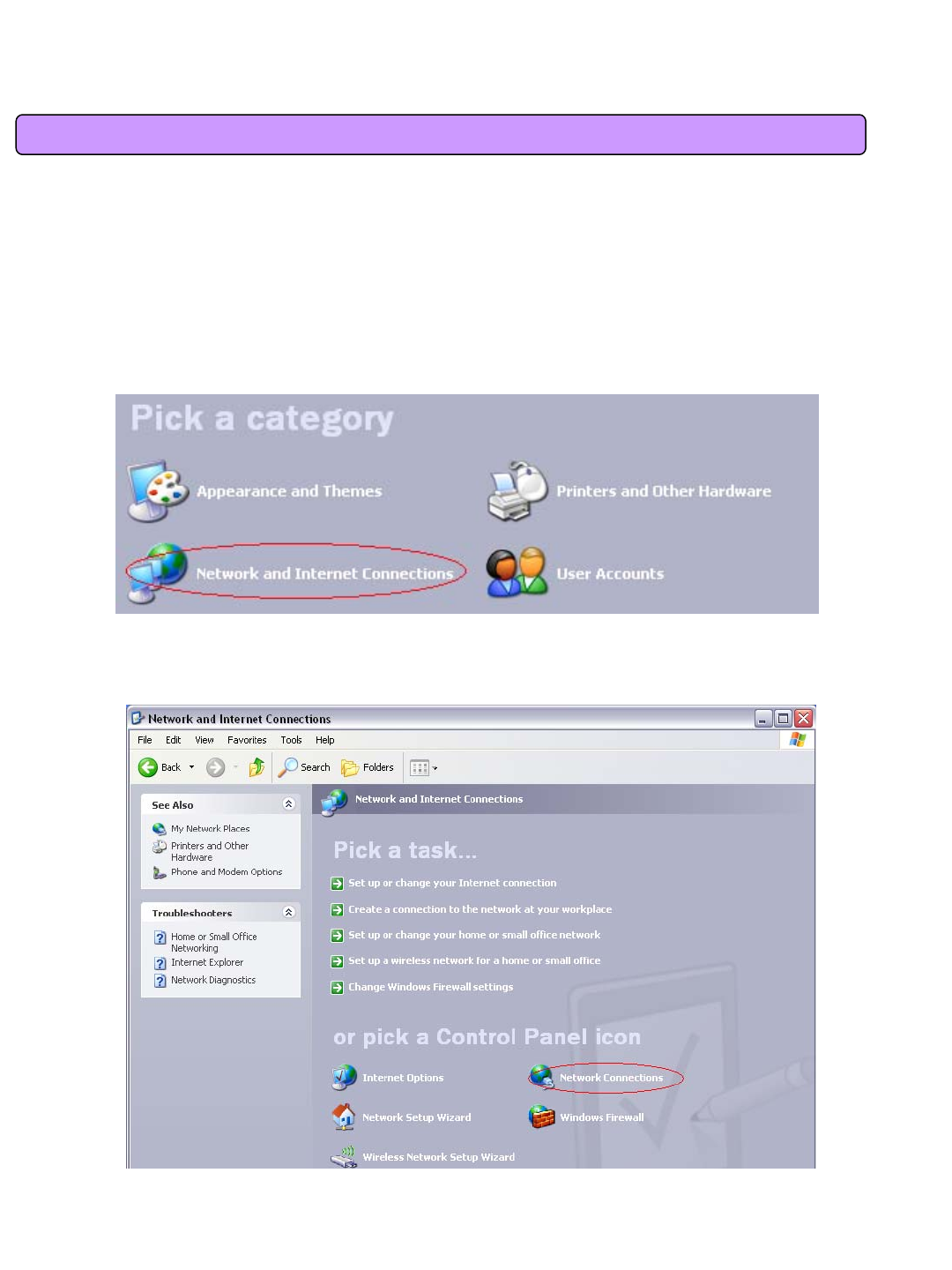
-Click on the Windows Start button, select Settings >> Control Panel on the menu.
-Double-click the “Network Connection”icon on the Control Panel.
<Double-click the Network and Internet Connections > …
<Double-click the Network Connection>
22
3.3 Windows XP Setup
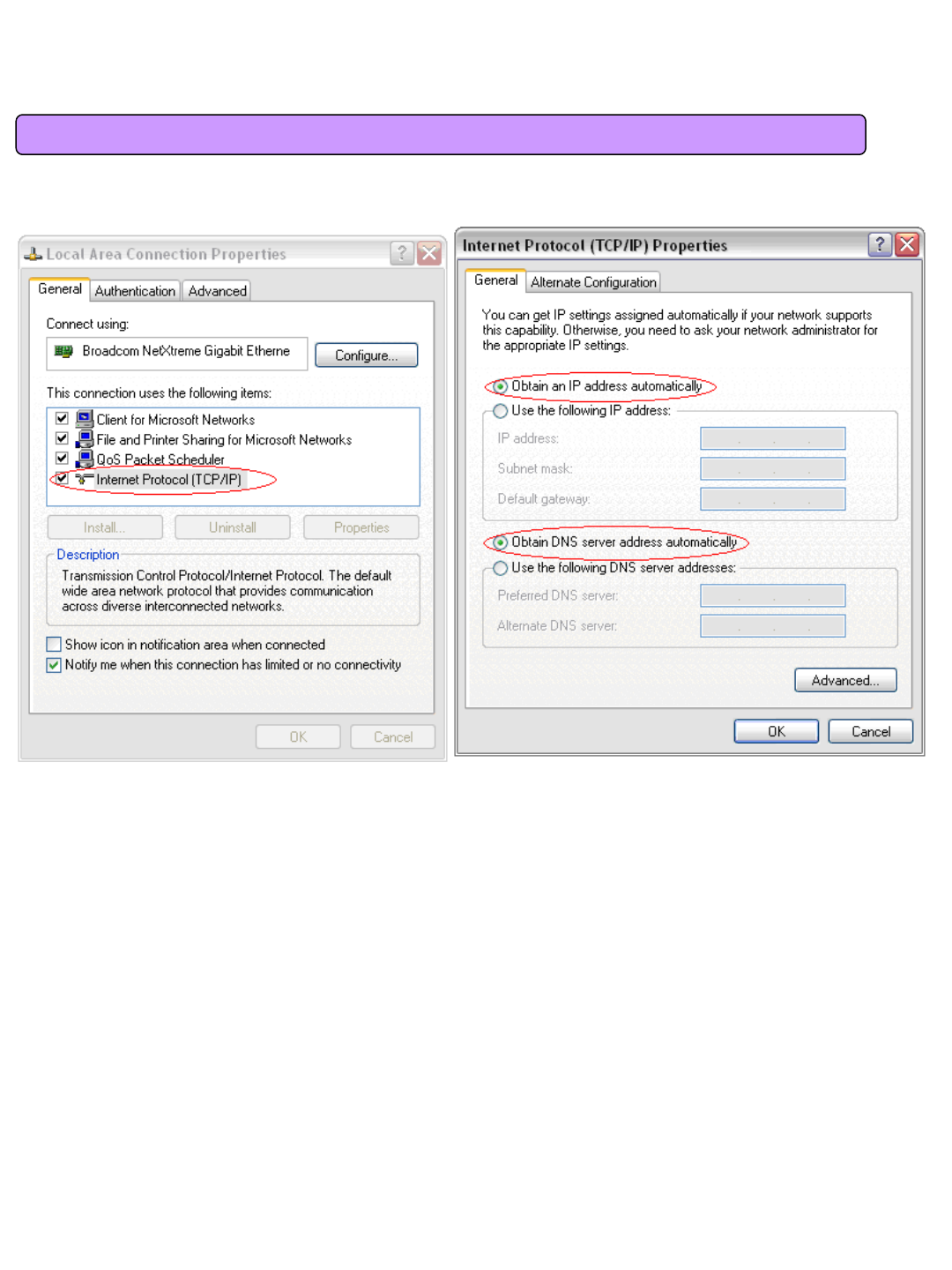
- Double-click the Local Area Connection from the Network Connection to select.
- Click Properties in the Local Area Connection Status to select.
<Double-click Properties>
<Double-click the Local Area Connection>
23
3.3 Windows XP Setup
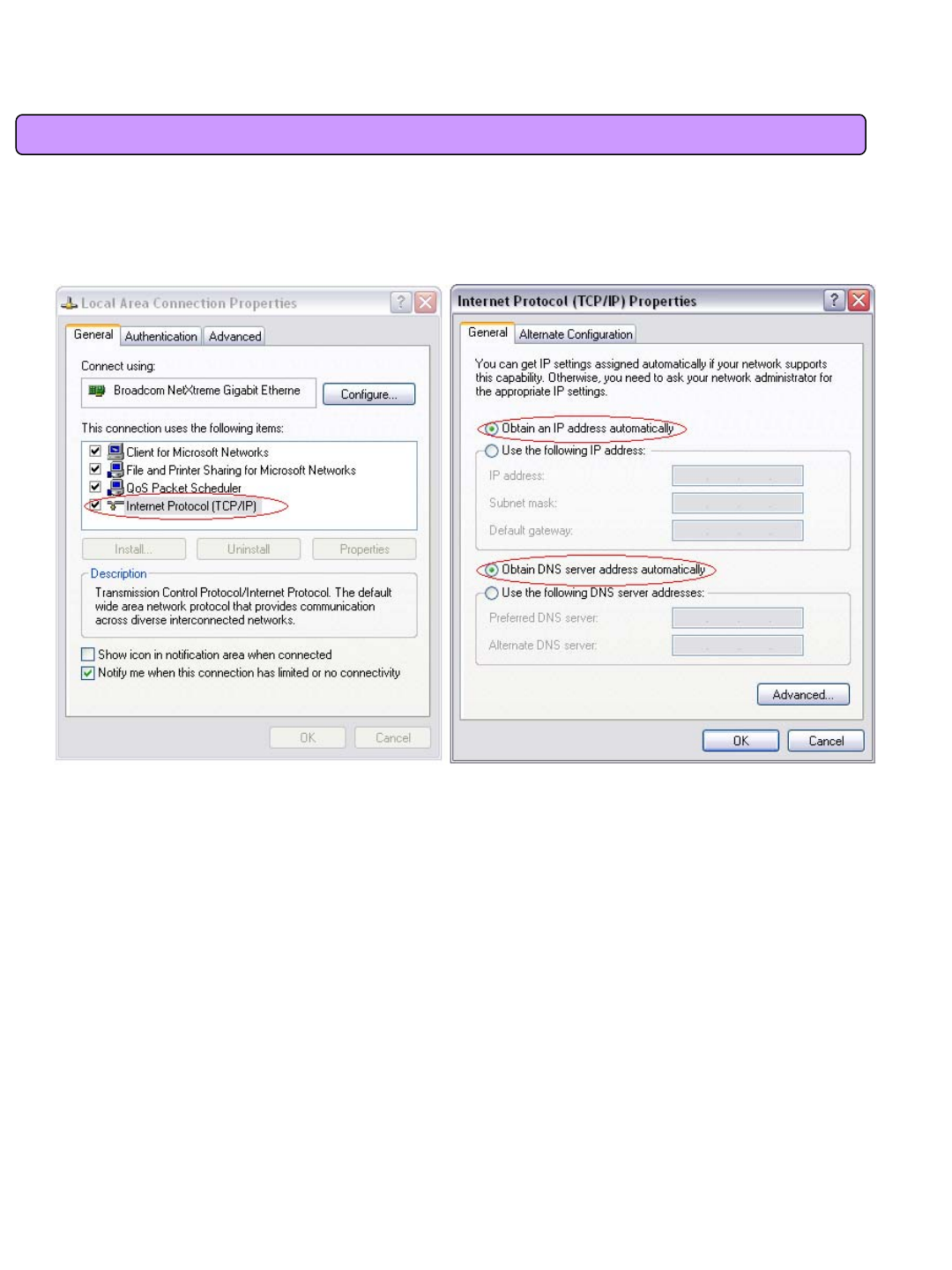
<Select the
‘Obtain an IP address automatically’,
‘Obtain a DNS Server address automatically’and
click OK>
- Double-click Internet Protocol (TCP/IP) and then select the Obtain an IP address automatically and
Obtain a DNS Server address automatically.
<Double-click TCP/IP >
- After completion of setup, click OK button and close all of Local Area Connection Properties windows.
- When TCP/IP setup is completed, IP address is automatically assigned by VoIP CPE. For automatic
assignment, PC and VoIP CPE should be connected with a LAN cable. If it is not connected with a cable,
connect the cable and restart the PC.
- You can check the automatic IP address assignment by using the ipconfig command from Command
Prompt.
24
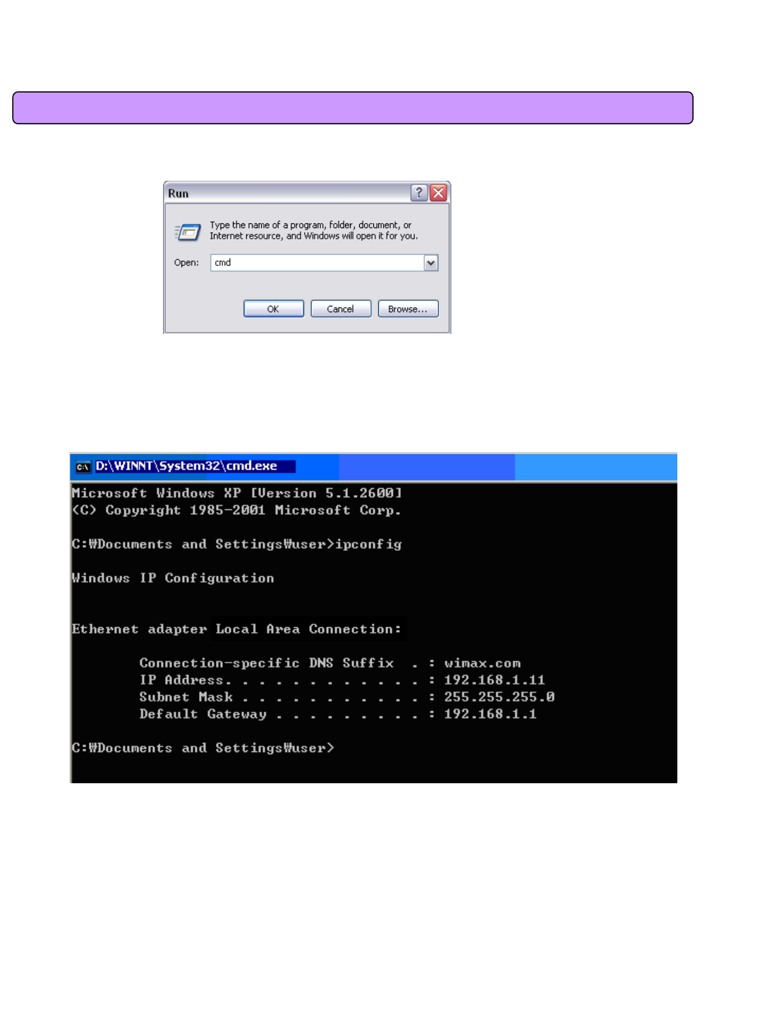
3.3 Windows XP Setup
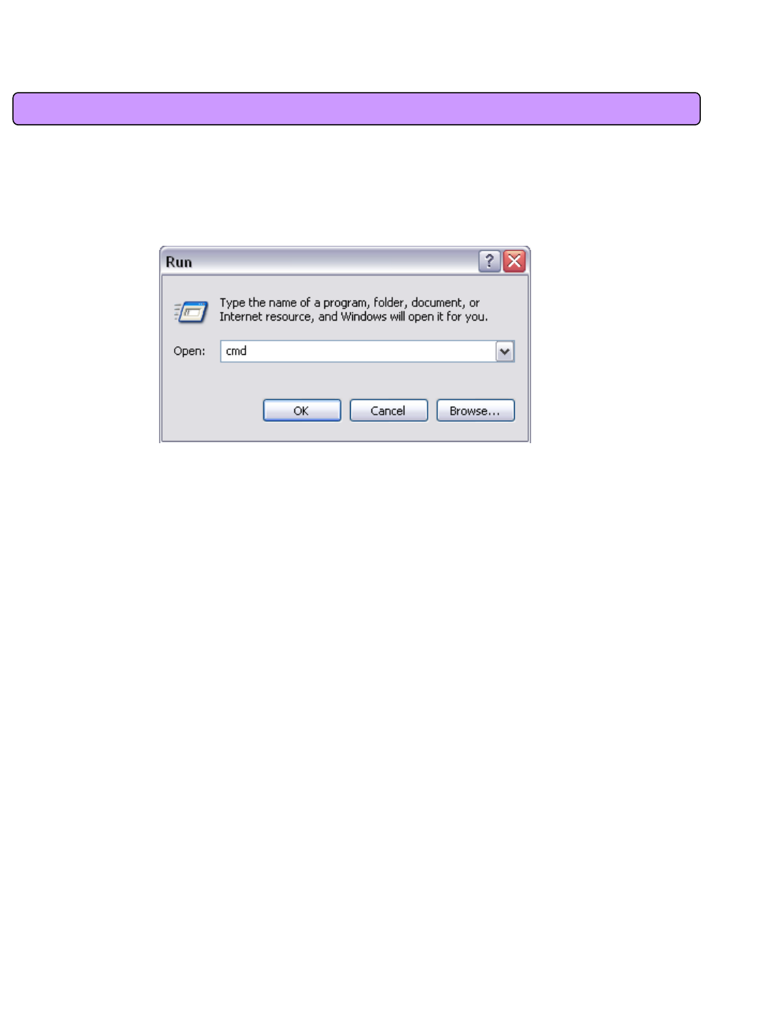
- To run the Command Prompt, click the Start button on the lower left corner of Windows screen and click
Run to enter “cmd”in the Open box, and then click OK button.
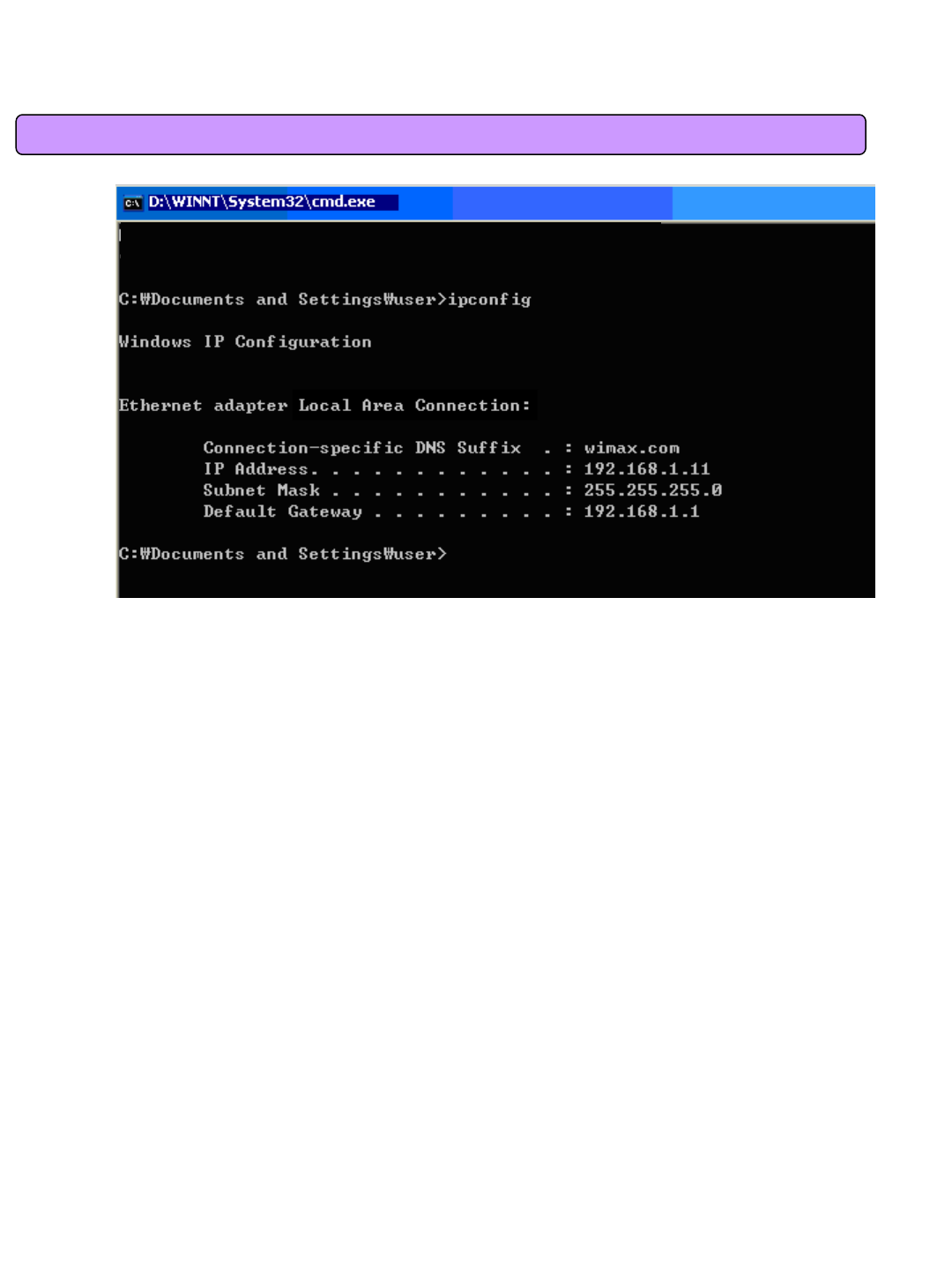
- When the Command Prompt runs, enter the “ipconfig”command to verify IP address, Subnet mask, and
Gateway, which are automatically assigned to PC.
[Note] All PCs connected to VoIP CPE will get each of assigned IP addresses respectively.
IP Address: 192.168.1. 100~150
Subnet Mask: 255.255.255.0
Default Gateway: 192.168.1.1
[Note] If IP address is not assigned normally, check the following and restart PC so as to check
if the IP address is assigned.
-LAN cable connection between PC and VoIP CPE
-Check TCP/IP setup details
<Run cmd>
<Verify IP address>

25
4. VoIP CPE Internet Connection
This chapter describes how to connect VoIP CPE to Internet. Internet connection setup is made by
accessing to internal web setup screen. Therefore, Internet connection setup can be done from one of PCs
connected to the VoIP CPE by executing just once.
To access to the web server built in the VoIP CPE, you have to set up PC normally.
For details how to set up PC, refer to Chapter III of this manual.
Internet connection setup is possible through internal web server in the VoIP CPE.
The Chapter IV describes how to proceed Internet setup by using this web server.
When completing the setting of PC and VoIP CPE according to the instructions from Chapter II to Chapter IV,
you can use Internet from the PC connected to VoIP CPE.
In case of the cable modem mode Internet service environment, proceed the Chapter II of this manual and
then turn off power to both modem and router. Turn the modem on and next the router on when linked after
about 1 minute, then they will be connected without any separatesetup.
- It may not connected immediately depending on user environment, and follow the instructions of this
Chapter IV.
26
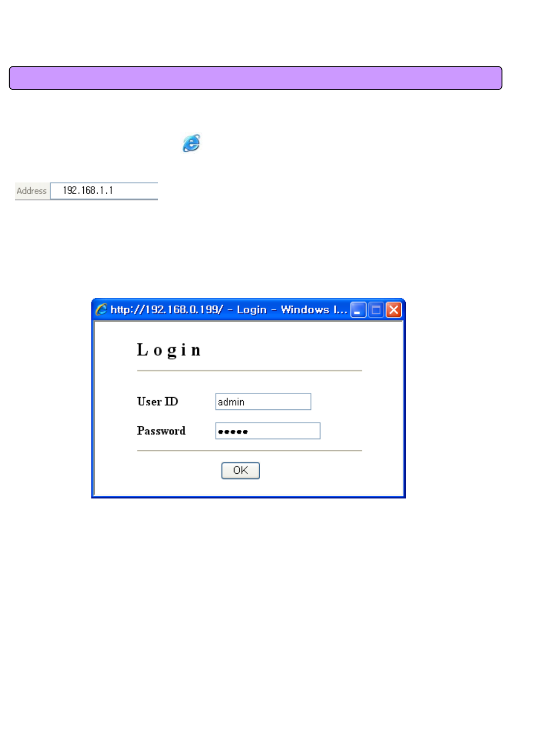
You can access to the web server built in the VoIP CPE, even in the environment not connected to Internet.
To access to the web server, run Internet Explorer and input 192.168.1.1, the address of VoIP CPE, in
the address box as shown below.
4.1 Access to the VoIP CPE Built-in Web Server
[Note] If PC is connected to the VoIP CPE normally but not connected to Internet, only inputting the
address of 192.168.1.1 in the address box correctly can lead to be connected to the VoIP CPE web server.
This function may not operate in specific environment.
Accessing to the…VoIP CPE, the following Login screen will be displayed.
The default user ID and password are admin, which you can change on the web server.
27
5. VoIP CPE WiMAX Connection and Setup
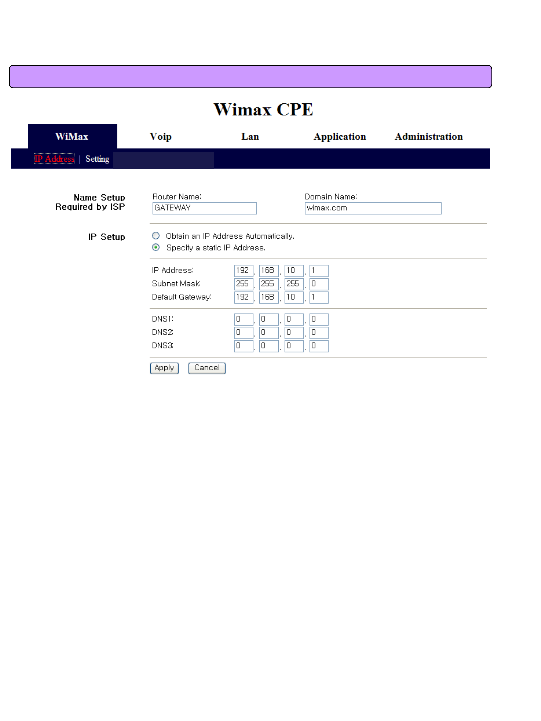
This screen is to set the mode assigning the IP address from the WiMAX modem. You can not only
assign the host name and domain name of VoIP CPE but also set the IP address to DHCP(Dynamic
IP) or Static IP address.
5.1 IP Address Setup
28
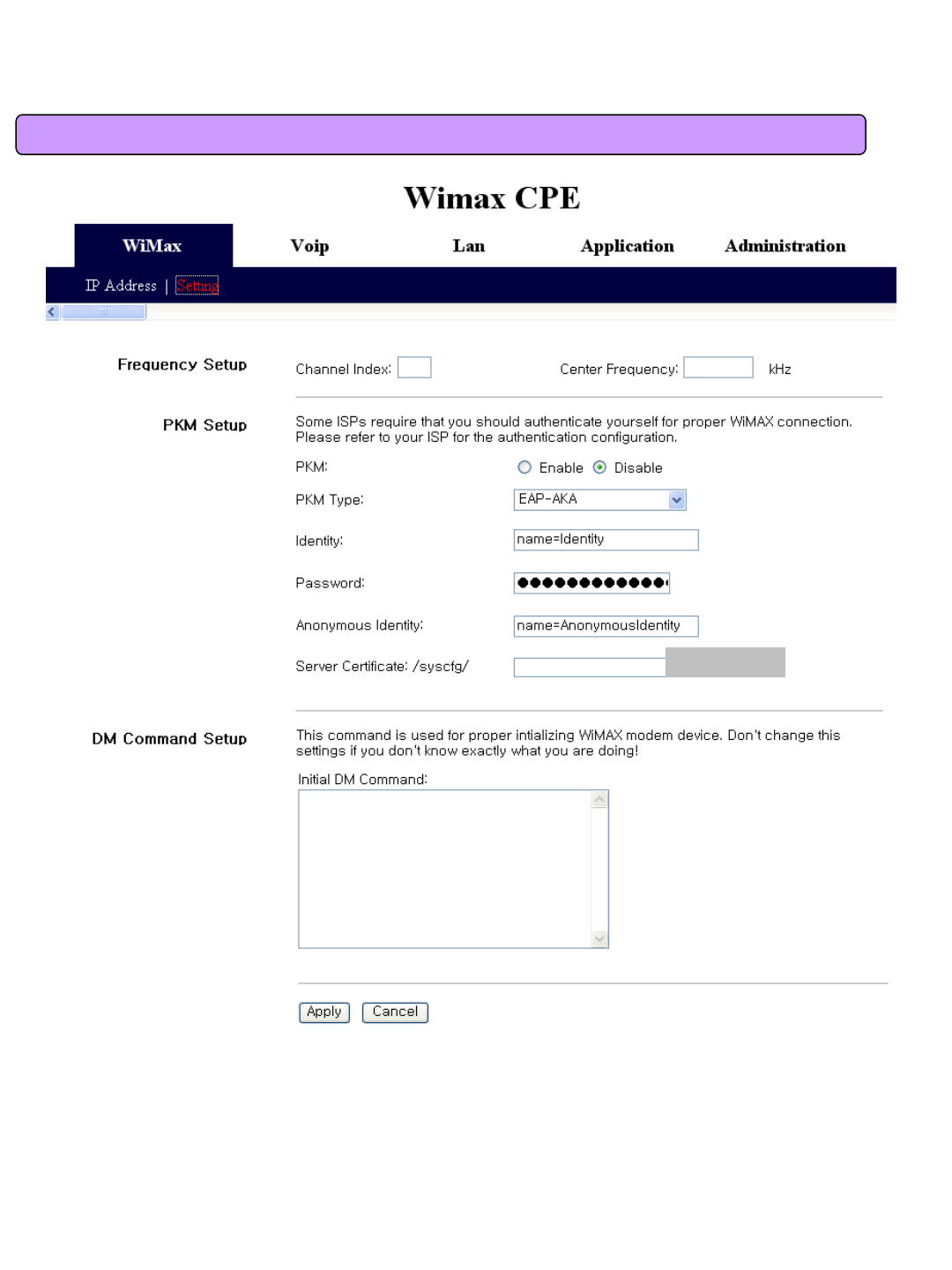
The screen is to perform various settings for WiMAX modem. You can assign whether or not to use
the PKM Authentication on the top and accordingly set the PKM Authentication mode, ID/Password,
anonymous ID, and ISP Certificate in the VoIP CPE.
At the bottom, you can assign to perform customized command at initial boot of WiMAX modem. It
is used when any particular setup is required for base station (BS) by the corresponding ISP.
5.2 WiMAX Modem Setup
Browse
29
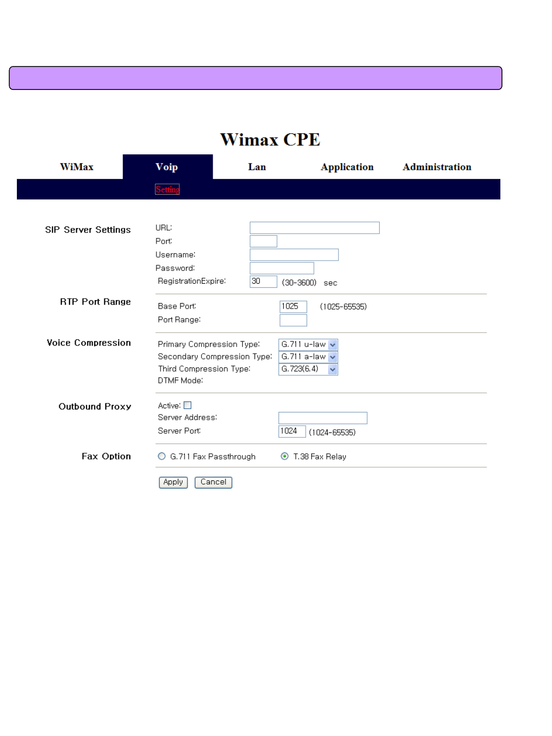
This screen is to perform all kinds of set up related VoIP. In first, you can assign SIP URL, Port,
Username, Password, Registration Expire. Secondly, can select RTP Port Range. Thirdly, set up the
Voice Compression type, Primary, Secondary, Third compression Type. In the following section, you
can set up ‘Outbound Proxy’ . In last item, can select Fax Option.
6.1 VoIP Setting
6. VoIP CPE Setup
30
7. VoIP CPE LAN Setup
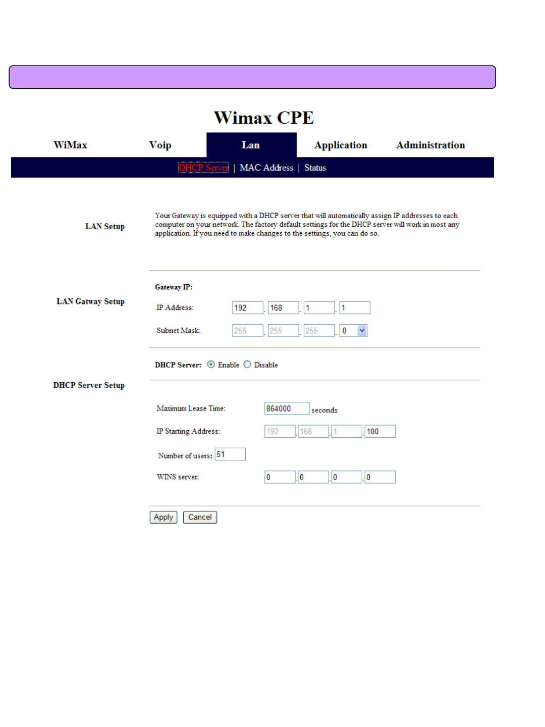
This screen is to perform all kinds of setup related internal LAN.
First of all, you can assign the IP address of gateway and subnet mask to be used in the LAN that
VoIP CPE manages. If you use the system by linking with external router, some cases may need
setup change, otherwise you can use default value.
The following describes setting up whether or not to use DHCP and detailed information.
By using DHCP, you can decide whether or not to give the IP address automatically to each PC
connected to VoIP CPE, and additionally set up the expiration date of IP address, DNS Relay(you
have to set the DNS in the IP Address tap of WiMax part(5.1 IP Address Setup)), the range of IP
address, and IP address of WINS Server.
7.1 DHCP Server Setup
31
This screen is to change MAC address used for internal LAN connection. In most of cases you can
use default setup.
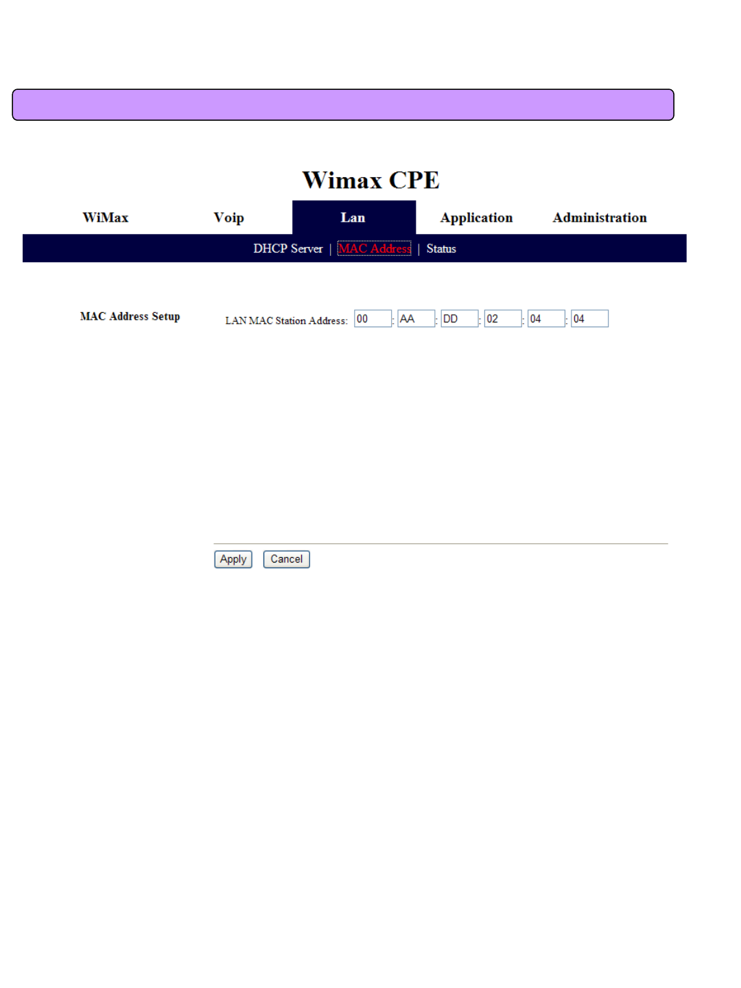
7.2 MAC Address Setup
32
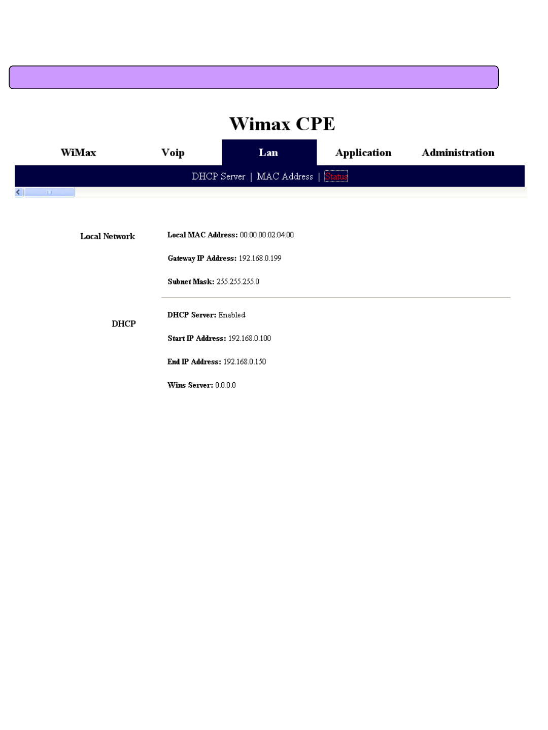
This screen displays all sorts of status information on internalLAN.
7.3 LAN Status Information
33
8. Application Support Setup
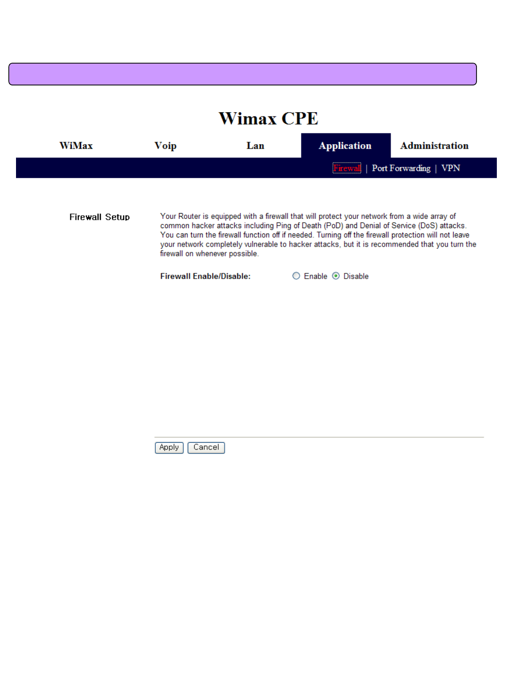
This screen is to set whether or not to use firewall. Using firewall enables to set VoIP CPE to being
not affected by hacking from the outside, including Ping Flooding or DoS. Internal LAN PCs are
usually isolated/protected from external Internet even though they do not use firewall, but it is
preferable to use firewall to be ON as possible. Default value is set to using firewall.
8.1 Firewall Setup
34
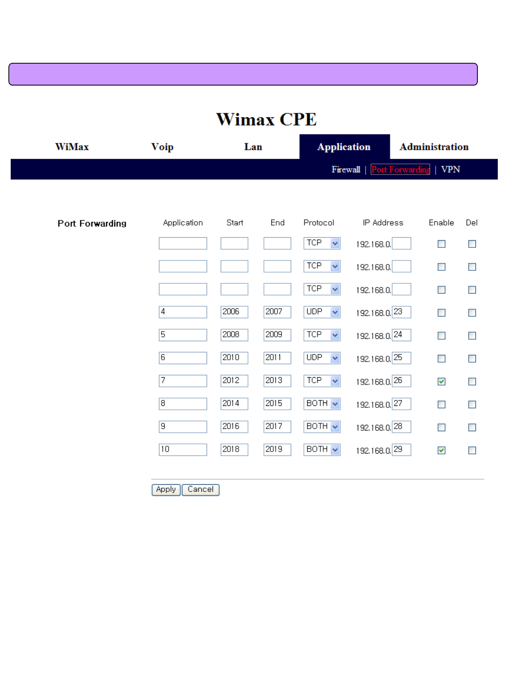
Port Forwarding function is used to forward incoming packets of specific TCP/IP port from outside
to the assigned PC. If you have to use programs, such as VoIP and P2P, or have to operate servers,
such as HTTP and FTP, in a PC of internal LAN, packets from outside may be forwarded.
8.2 Port Forwarding
35
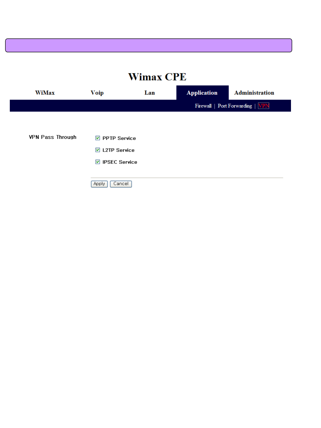
VPN (Virtual Private Network) function is used to get access to security network installed in a
company or organization via Internet network.
If there is a VPN Server outside and one has access to the VPN Server via Internet network by using
VoIP CPE, this screen shows to activate security protocol supported by the appropriate VPN Server.
Supportable protocols include IPSec, PPTP, and L2TP.
8.3 VPN Pass through Setup
36
9. Administrator Function Setup
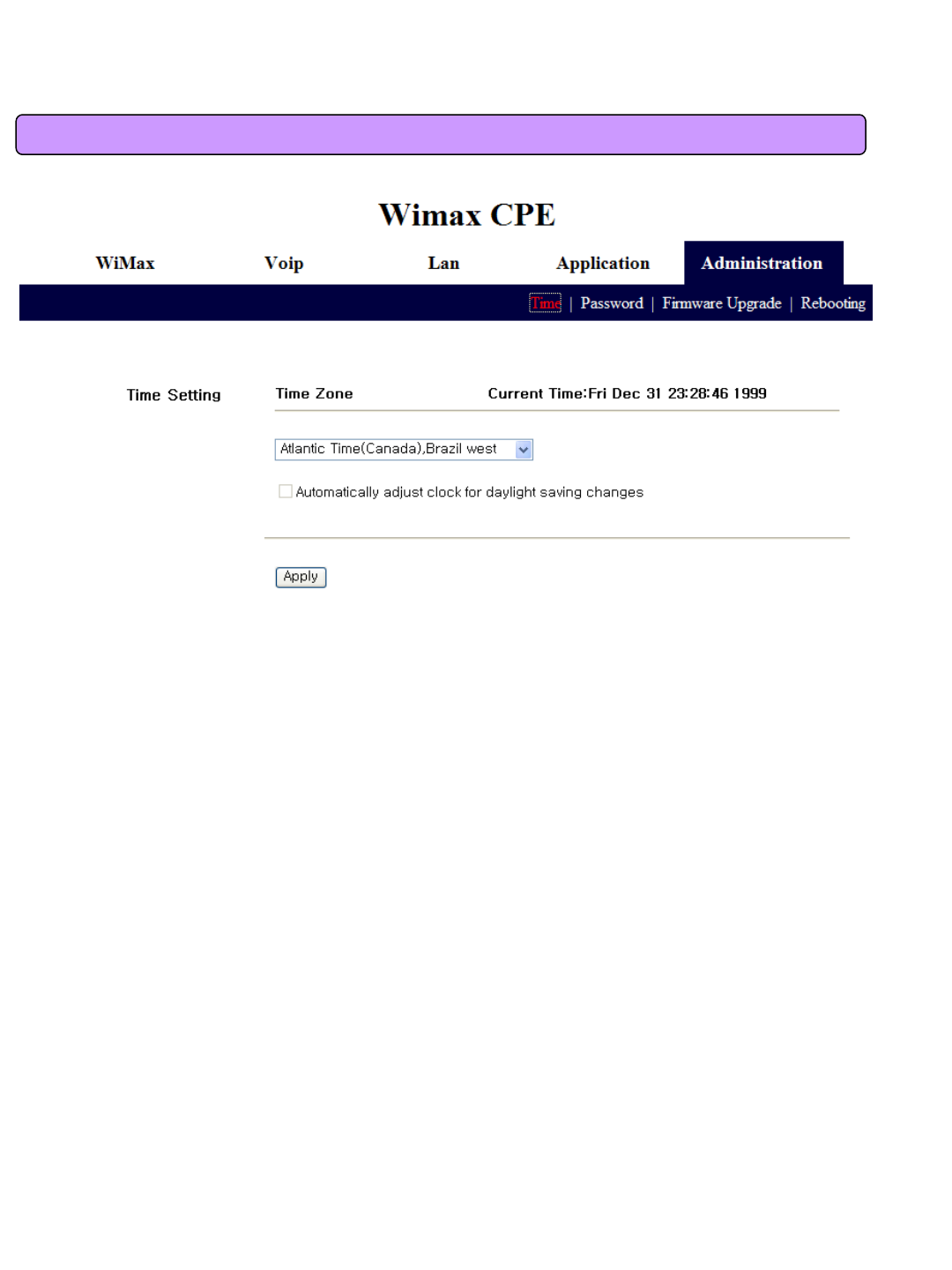
9.1 Administrator Time Server
The ‘Time’ function is to set up time of the VoIP CPE system. Please select your time zone.
37
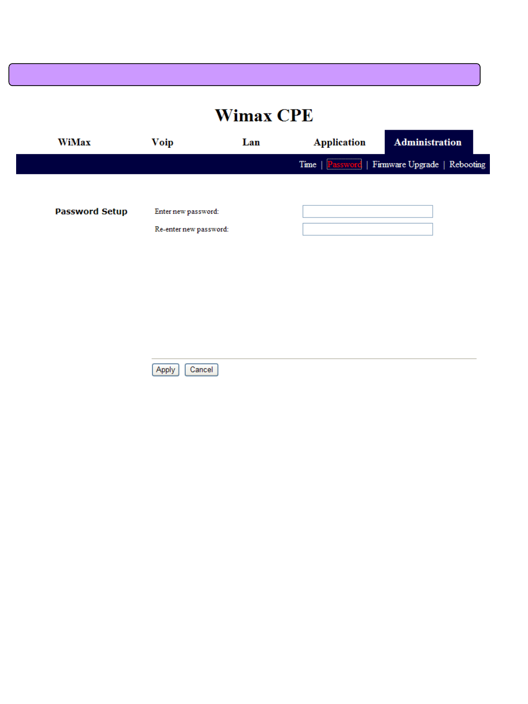
9.2 Administrator Password Setup
This screen is to set up Password to be given to Administrator who manages all setups of VoIP CPE.
Default password is “admin”and by changing the default password he can input and use the
password set up every time he/she gains first access to web interface.
38
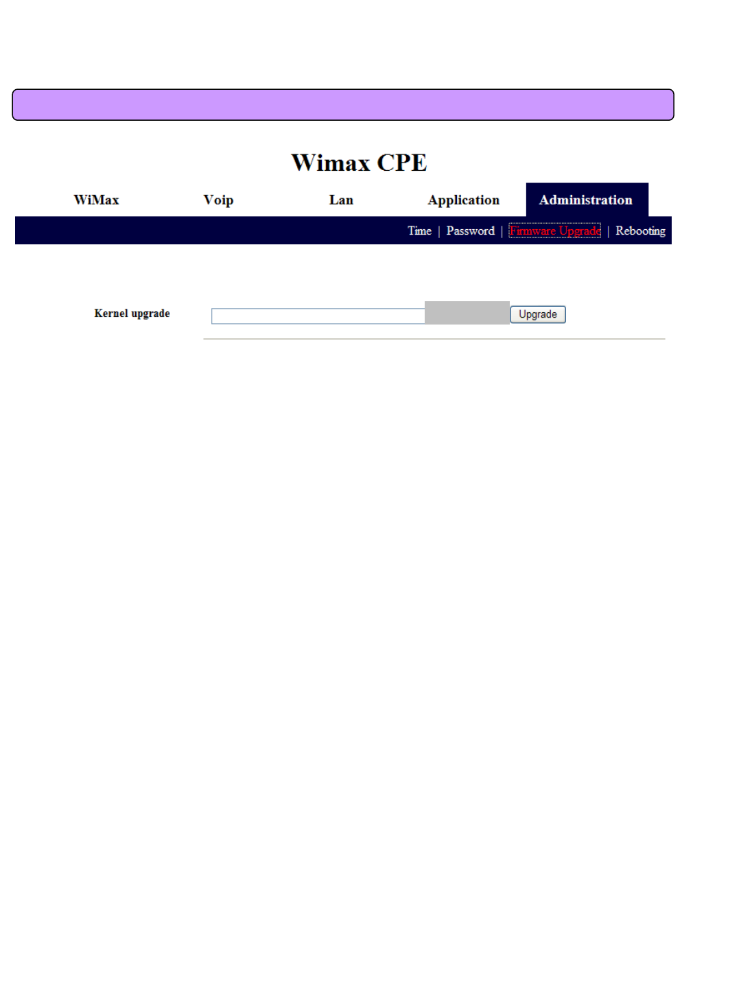
9.3 Administrator Firmware Upgrade
The screen is used for Firmware Upgrade. If there is a Firmware Upgrade file, press the Browse
button to select and press the Upgrade Now button to start Firmware transmission and Upgrade. It
takes about 2-3 minutes for Firmware Upgrade. And please pay attention because interruption
during upgrade may cause damage to or malfunction of VoIP CPE. When Firmware Upgrade is
made properly, red letters in the upper part of the screen will be changed to a blue message that
Upgrade is completed. Reboot to apply upgraded firmware, like reset to factory default.
Browse
39
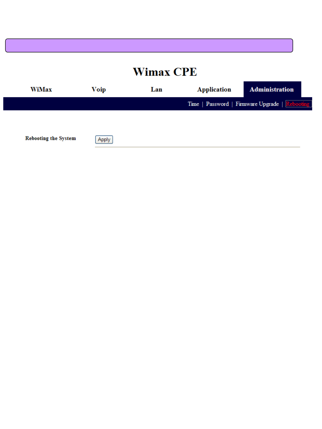
9.4 Administrator Rebooting
The Reboot tab is used for rebooting the VoIP CPE via the web-based configuration page. To apply
any changes, you should reset the VoIP CPE using ‘Apply’ button.
40
10. References
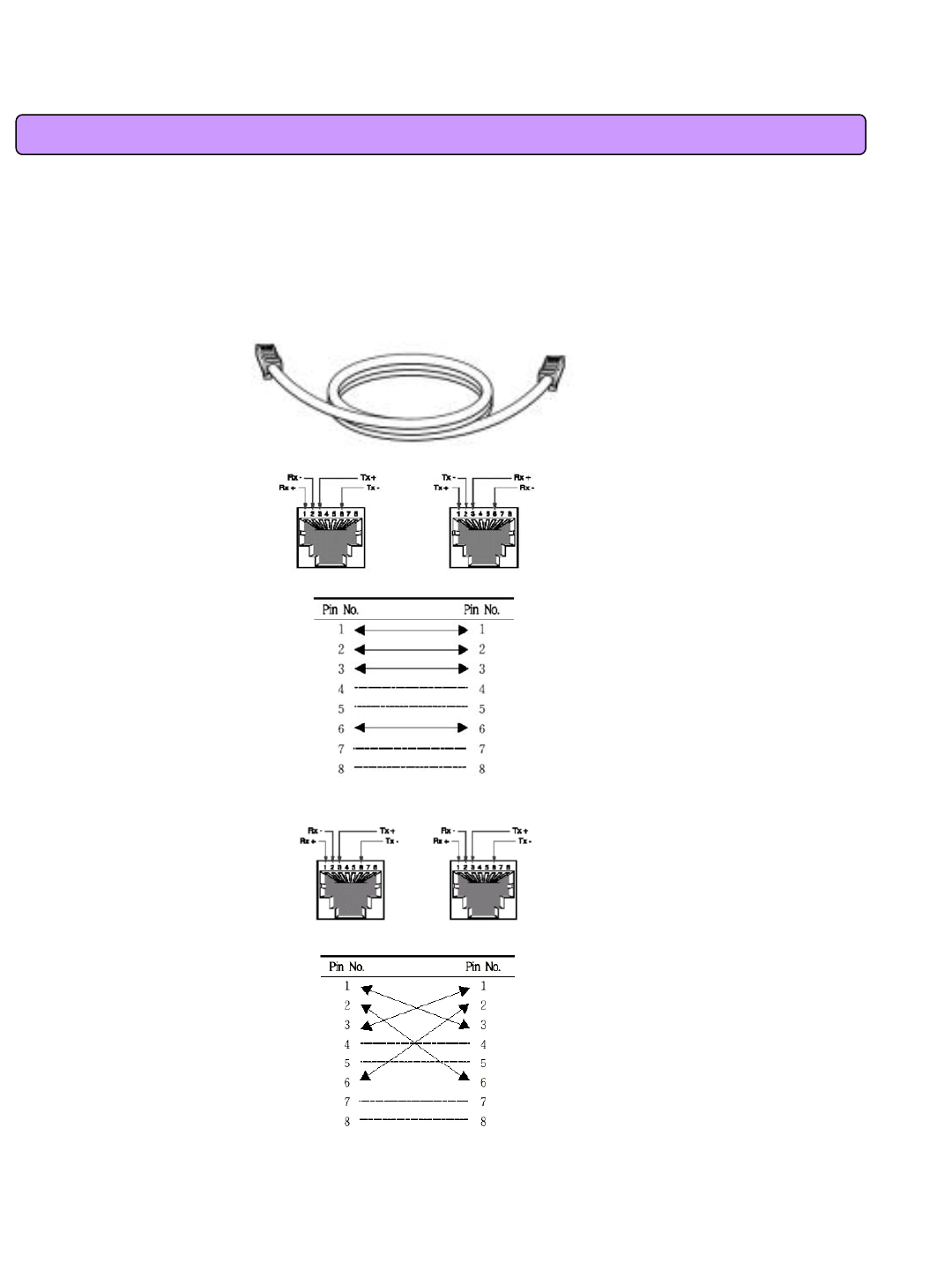
10.1 LAN CABLE Standards
LAN Cable includes straight cable (direct cable) and cross cable.
VoIP CPE has Cable Auto Sense feature, so either of the two can be used.
However, it is not possible of normal communication if you use the cable that does not maintain the
#1-2 and 3-6 twisted pairs according to the regulations. Always manufacture or purchase
regulation cables to use.
<Structure of Direct Cable > <Structure of Cross Cable>
41
10.2 IP Router PING Test Method
PING Test through router in the PC shows whether PC is normally connected to IP router or not. You
must check if the IP address of your PC is normal before PING Test.
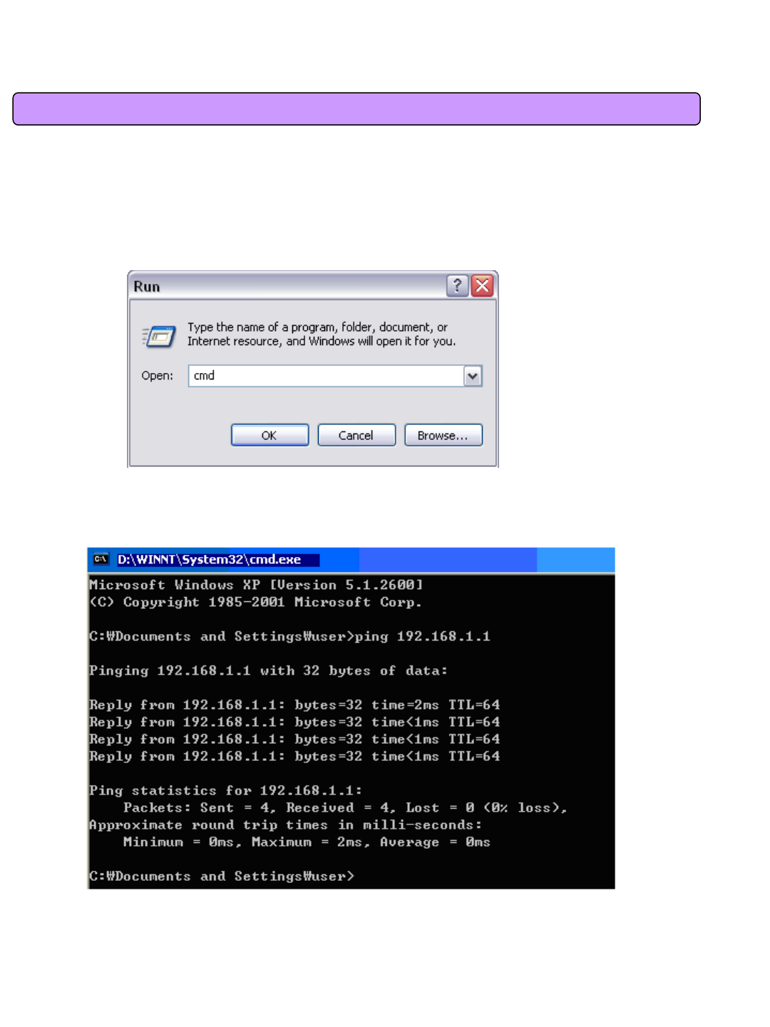
To perform a PING Test, run MS-DOS in Win98/ME, while Command Prompt in Windows 2000/XP.
To do this, click the “Start”button at the lower left on the Windows screen and select “Run”.
In the Open dialog box, enter “command”in case of Windows 98/ME, while “cmd”in Windows
2000/XP, and then click OK button to run MS-DOS or Command Prompt.
<Run “command”or “cmd”>
Enter “ping 192.168.1.1”command in MS-DOS or the Command Prompt window.
<Running the Ping 192.168.1.1 command and its result >
If four messages “Reply from….”appear as shown in the above figure, you can verify normal
connection between IP router and PC so that there may be no problem in communication.

42
10.3 Product Specification
Parameter Description Parameter Description
WiMAX System
Profile IEEE 802.16e, Wave 2
compliant Receiver
Noise Figure Under 7dB @ High Gain Mode
Multiple Access OFDMA RF Sensitivity -88dBm @QPSK1/2
Frequency
Band 2.3GHz / 2.5GHz UICC UICC Support(1.8/3.0/5.0V)
Maximum RF
Output 23dBm(200mW) SAR Limits Comply with FCC regulation
Antenna Enternal 2 ANT (1 ANT Gain
= 5dBi) Power Host Power 3.3V
Service Only data Power
Consumption Under 1W
Channel
Bandwidth 8.75 or 10MHz for 2.3GHz
5 or 10MHz for 2.5GHz TX / RX
Configuration SISO(1Tx, 1Rx) / MISO(1Tx, 2Rx)
Modulation DL : QPSK, 16-QAM, 64-
QAM
UL : QPSK, 16-QAM Transfer Rate Wave1 = DL : 10Mbps / UL : 4Mbps
Wave2 = DL : 20Mbps / UL : 6Mbps
Interface to
Host Mini PCI full size Authentication
and Security PKM V2-EAP/EAP-AKA/EAP Client

43
10.4 Troubleshooting(Actions to be taken when internet is disconnected)
1. Check the status of external type modem.
: Check if Link lamps of cable, modem is turned ON.
2. Check the LED status of VoIP CPE.
1) Check if POWER LED is turned ON.
2) Check if LEDs of WiMAX are turned ON.
3) LAN port, check if the lamp of the port connected to PC is turned ON.
3. Check the IP address of PC.
1) In case of Windows 98/ME, click [Start] -> [Run] and enter the [winipcfg] command to
pop up the [IP Address] window, and then check the [IP Address].
2) In case of Windows 2000/XP, run [Command Prompt] and enter the [ipconfig] command
to check the [IP address].
4. If IP Address is not normal –Set the IP Address of PC manually.
If IP Address is normal –Go to 5.
1) In case of Windows 98/ME
① Execute [Run -> Control Panel -> Network] and then click Properties of [TCP/IP] for LAN
card.
② Check [Use the assigned IP address], enter [192.168.1.100] for [IP Address] and
[255.255.255.0] for [Subnet Mask].
③ Select [Gateway] and enter [192.168.1.1] for [New Gateway], and then click on [Add]
button.
④ Select [DNS Configuration], check [Use DNS], enter any name in [Host], enter [DNS
Server Address to search], and click [Add] button.
⑤ Click [OK], and click [OK] again on the [Network Properties] window, and then click [OK]
from the [Change System Setup] window to reboot the PC.
2) In case of Windows 2000
① Execute [Start -> Control Panel -> Network and Dial-UP Connections], double-click [Local
Area Connection], and click [Properties].
Click Properties of [Internet Protocol (TCP/IP)] among Components.
② Click [Use the following IP address].
③ Enter [192.168.1.100] for [IP Address], [255.255.255.0] for [Subnet Mask], and
[192.168.1.1] for [Default Gateway].
④ Click [Use the following DNS Server Address].
⑤ For [Basic Setup DNS Server],enter communication company server of each
country.
⑥ Click [OK] button. Click [OK] again in the [Local Area Connection Properties] window.

44
10.4 Troubleshooting(Actions to be taken when internet is disconnected)
3) In case of Windows XP
① Execute [Start -> Control Panel -> Network and Internet Connection], double-click
[Local Area Connection], and click [Properties]. Click Properties of [Internet Protocol
(TCP/IP)] among Components.
② Click [Use the follwing IP address].
③ Enter [192.168.10.100] for [IP Address], [255.255.255.0] for [Subnet Mask], and
[192.168.1.1] for [Default Gateway].
④ Click [Use the following DNS Server Address].
⑤ For [Basic Setup DNS Server],enter communication company server of each country.
⑥ Click [OK] button. Click [OK] again in the [Local Area Connection Properties] window.
5. Run [MS-DOS] or [Command Prompt] and then perform PING Test with [192.168.1.1]. A
message [Reply from 192.168.1.1: bytes=32 time=1ms TTL=64] should appear when running
[ping 192.168.1.1] command. If the result of Ping test may not come properly, please contact
the Customer Support Center.

45
10.5 Product Warranty and Customer Support
Product Warranty
Product Name: Gateway Modem Model Name: SWC-2000
This product comes with a one-year warranty and its compensation will be based on the following:
Contents of Warranty Rules
1. Equipment for Warranty: VoIP CPE
2. Warranty Period: 1 year
3. Free repair service
- If a defect or failure of the product occurs within the warranty period
4. Charged repair service
- If a defect or failure of the product occurs after the expiration of the warranty period
- If a defect or failure of the product occurs due to a natural disaster such as fire, flood,
and lightening
- If a defect or failure of the product occurs due to any alteration or repair work
- If a defect or failure of the product occurs due to other consumer faults
SEOWONINTECH.CO.,LTD.
R&D Center 689-47, Kumjung-Dong, Kunpo-City, Kyunggi-Do,
435-862, Korea
Tel : 82-31-428-9531 | Fax : 82-31-428-9598
e-mail : wimax@seowonintech.co.kr
http://www.seowonintech.co.kr
Regulatory Notices
Caution: The WiMAX device has been tested for compliance with FCC RF exposure
limits. The WiMAX device should not be used with external antennas that are
not approved for use with this device. Use of this device in any other
configuration may exceed the FCC RF exposure compliance limits.
To comply with FCC RF exposure compliance requirements, a separation distance of at
least 20 cm must be maintained between the antenna of this device and all persons.
This equipment generates, uses, and can radiate radio frequency energy and, if not
installed and used in accordance with the instructions, may cause harmful interference to
radio communication. There is no guarantee that interference will not occur in a particular
installation
This equipment has been tested and found to comply with the limits for a Class B digital
device, pursuant to part 15 of the FCC Rules. These limits are designed to provide
reasonable protection against harmful interference in a residential installation. This
equipment generates, uses and can radiate radio frequency energy and, if not installed
and used in accordance with the instructions, may cause harmful interference to radio
communications. However, there is no guarantee that interference will not occur in a
particular installation. If this equipment does cause harmful interference to radio or
television reception, which can be determined by turning the equipment off and on, the
user is encouraged to try to correct the interference by one or more of the following
measures:
▪ Reorient or relocate the receiving antenna.
▪ Increase the separation between the equipment and receiver.
▪ Connect the equipment into an outlet on a circuit different from that to which the receiver
is connected.
▪ Consult the dealer or an experienced radio/TV technician for help.
Caution: Any changes or modifications not expressly approved by Sprint could void the
user’s authority to use the equipment.