SEOWON INTECH SWC-5100 WIMAX CPE User Manual
SEOWON INTECH CO., LTD. WIMAX CPE
UserManual.wiki
>
SEOWON INTECH
>
SWC 5100 User Manual
Manual
Navigation menu
Upload a User Manual
Namespaces
Wiki Guide
HTML
PDF
Info
Views
User Manual
Discussion / Help
Navigation
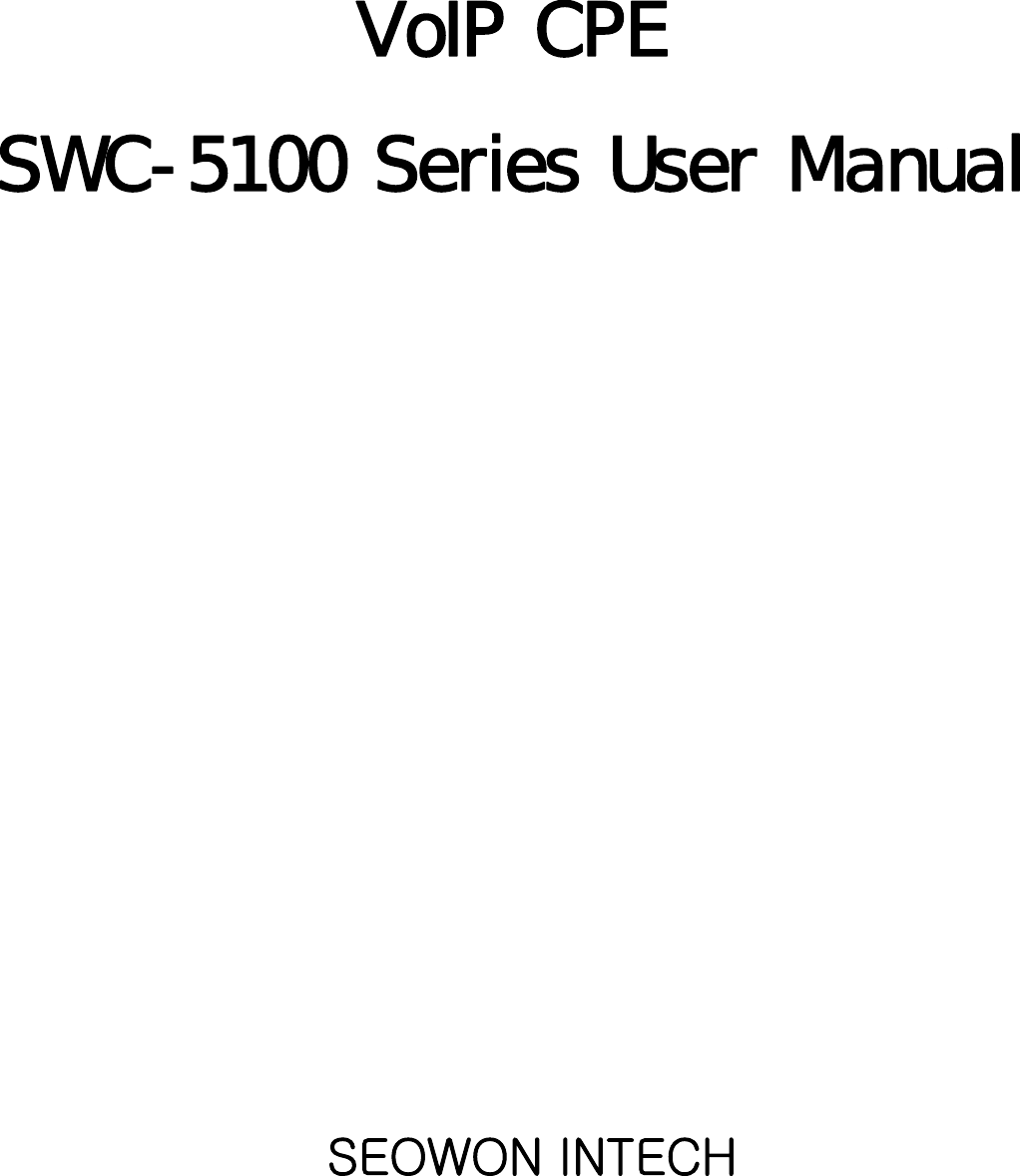
![Introduction to the Product Rear Side InformationAntenna1WiMAX DiversityAntenna2WiMAXMainPowerItem DetailsExternal Antenna Antenna1 : WiMAX DiversityAntenna2 : WiMAX MainDiversityMain SwitchHardwareResetPC TelePhone Power AdapterSeparable external antennaUser external type antenna attachable* Antenna Classification- 2.3G : M23- 2.5G : M25- 3.5G : M35LAN PC or Hub connectionPHONETl h tiPHONE Telephone connectionDC 12V Power Adapter connection (DC 12V 2.0A )POWER Power On/Off Switch (Switch between On/Off by pressing right or left) RESET Restore the VoIP CPE Factory Default 4[Note] If you lost LOGIN password forrouterorIP address afterchange, use the Resetswitch to restore its original Factory Default settings.](https://usermanual.wiki/SEOWON-INTECH/SWC-5100/User-Guide-1221131-Page-4.png)
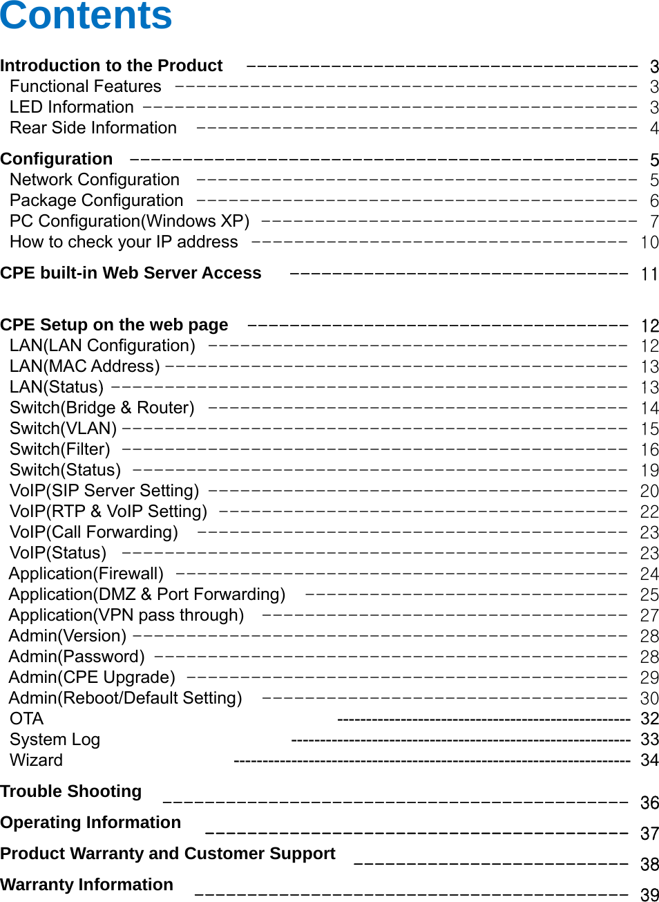
![ConfigurationHow to check your IP address• To run the Command Prompt, click the Start button at the lower left corner of theWindows screen. Click Run, then enter “cmd” in the Open box, and click OK.• When the Command Prompt window opens, enter the “ipconfig” command to verify theIP address, Subnet mask, and Gateway, which are automatically assigned to PC.<Run cmd>[Note] All PCs connected to CPE will receive their own assigned IP address.[Note]IfanIPaddressisnotassignedcheckthefollowingandthenrestartthePCand<Verify IP address>10[Note]IfanIPaddressisnotassigned,checkthefollowing,andthenrestartthePCandcheck whether an IP address is assigned.LAN cable connection between PC and CPECheck TCP/IP setup details](https://usermanual.wiki/SEOWON-INTECH/SWC-5100/User-Guide-1221131-Page-10.png)
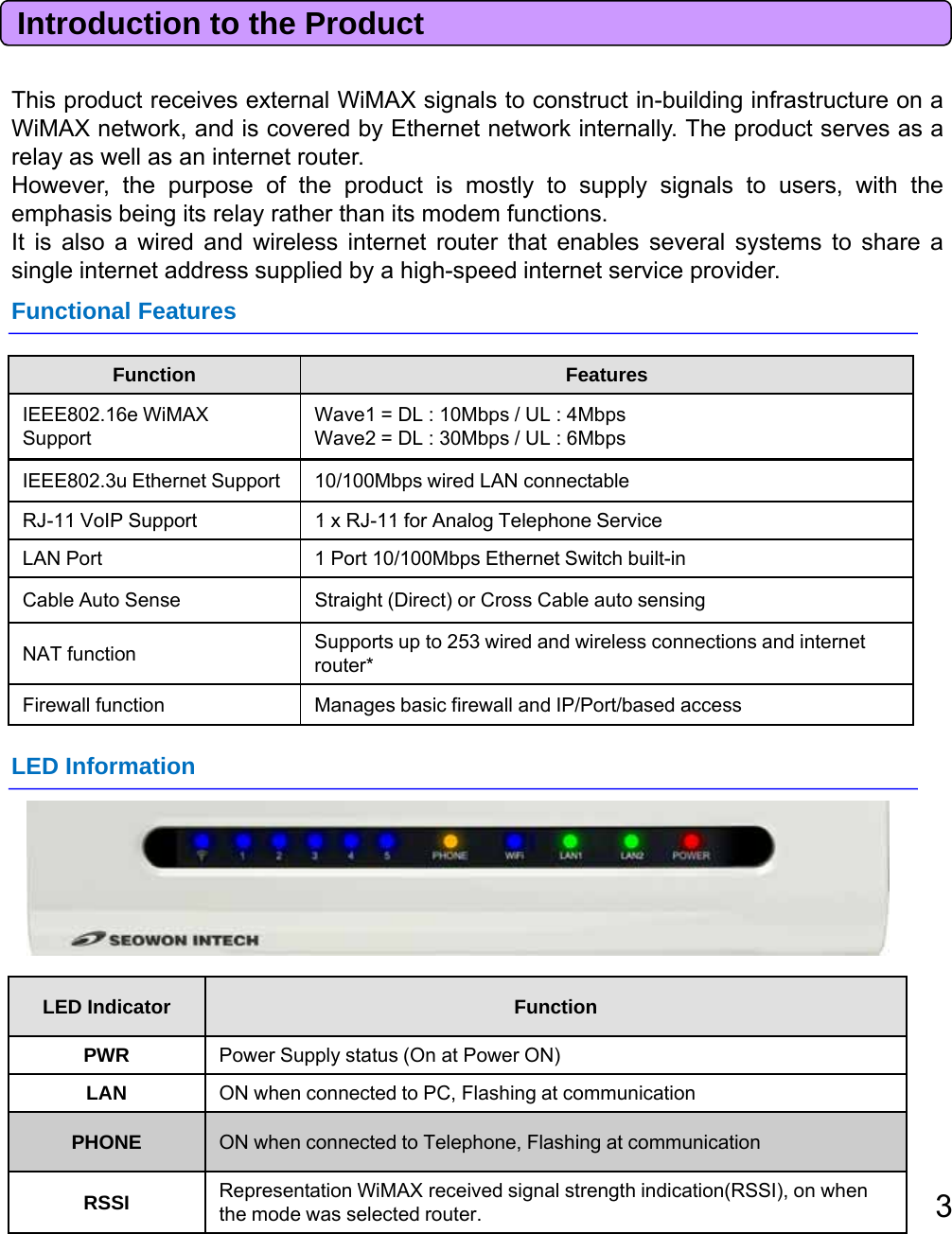
![ThWEBGUIidtCPEdiittttCPE Built-in Web Server AccessTheWEBGUIisusedto manage aCPEandviewits currentstatus.You can access the web server that is built into the CPE, even when not connected to theInternet.To access the web server, open Internet Explorer or your Browser and type “192.168.1.1”,which is the IP address of CPE, in the address bar, as shown below:[Note] If the PC is connected to the CPE but is not connected to the Internet, enteringthe IP address of 192.168.1.1 in the address box will connect the PC to the CPE webserver. This function may not operate in some environments.ID / Password = admin / adminUpon accessing the CPE, the following Login screen will be displayed.The default user ID and password are admin, which you can change on the web server.[Note] If you have no input activity for 1 hour, your web connection is terminated. In thisCase, please login again through the login page.11](https://usermanual.wiki/SEOWON-INTECH/SWC-5100/User-Guide-1221131-Page-11.png)
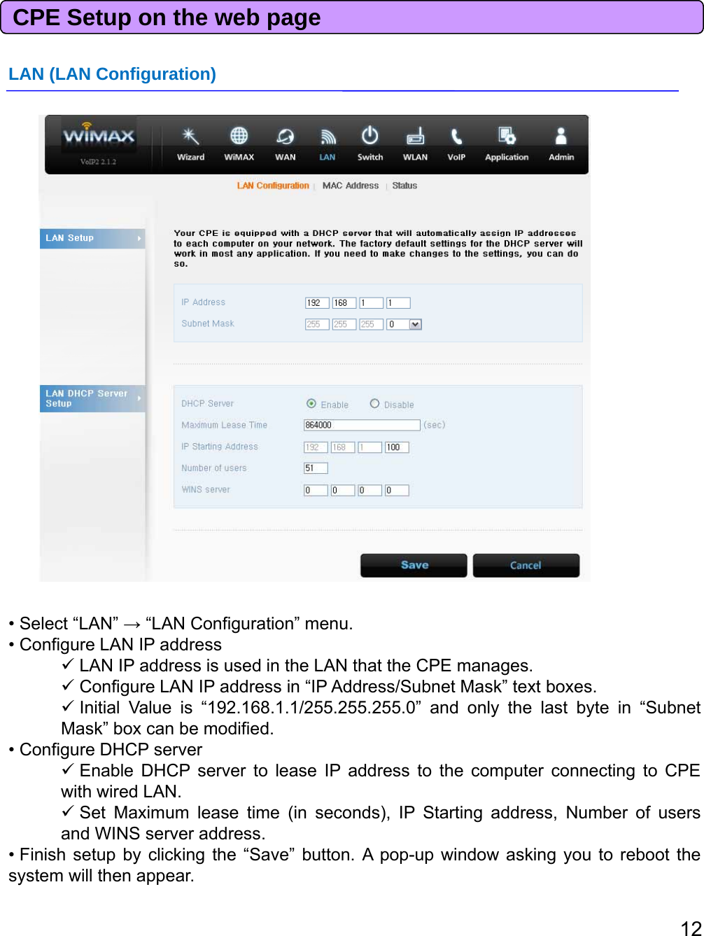
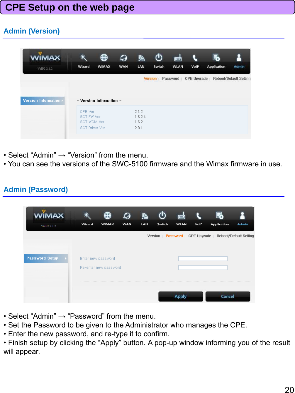
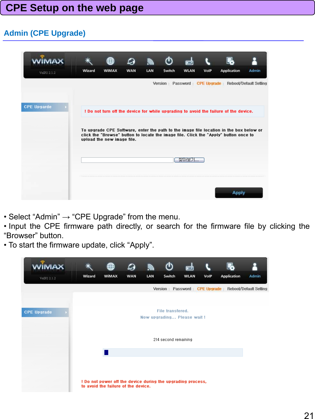
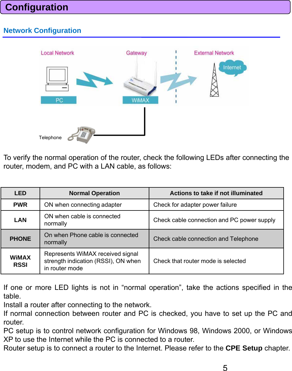
![CPE Setup on the web page• This will take several minutes, and time will vary according to the environment.• In some case, a pop-up window asking to rebuild the system will be opened due to aversion difference. If this occurs, click “Yes” to rebuild the system.• CPE is rebooted automatically after the upgrade process is complete.[Caution] To avoid failure of the CPE, do not power off the CPE during the upgradingprocess.Admin (Reboot/Default Setting)• Select “Admin” →“Reboot/Default Setting” from the menu.• Select “Reboot” to reboot the CPE.• Select “Reset to all default settings” to reboot the CPE and initialize CPE configuration.• To reboot the CPE, click “Apply”.• The CPE is rebooted automatically. This takes about 40 seconds.22](https://usermanual.wiki/SEOWON-INTECH/SWC-5100/User-Guide-1221131-Page-22.png)
![Trouble ShootingActions to be taken when internet is disconnected1. Check the status of external type modem.Check that the Link lamps of cable, modem are illuminated.2. Check the LED status of CPE.Check that the POWER LED is illuminated.Check if the LEDs of WiMAX are illuminated.ForLAN port, check that the lamp of the port connected to the PC is illuminated.3. Check the IP address of PC.For Windows 98/MEClick [Start] -> [Run] and enter the [winipcfg] command to open the [IP Address]window, and then check the [IP Address].For Windows 2000/XPR[C dPt]dtth[i fi ]dthkth[IPdd ]Run[CommandPrompt]andenterthe[ipconfig]commandtocheckthe[IPaddress].4. If IP Address is not normal – Set the IP Address of the PC manually.For Windows 98/ME1.Execute [Run -> Control Panel -> Network], and then click Properties of [TCP/IP] forLAN card.2.Check [Use the assigned IP address], enter [192.168.1.100] for [IP Address] and[2552552550]for[SubnetMask][255.255.255.0]for[SubnetMask].3.Select [Gateway] and enter [192.168.1.1] for [New Gateway], and then click [Add].4.Select [DNS Configuration], check [Use DNS], enter any name for [Host], enter[DNS Server Address to search], and click [Add].5.Click [OK], click [OK] again in the [Network Properties] window, and then click [OK]from the [Change System Setup] window to reboot the PC.24](https://usermanual.wiki/SEOWON-INTECH/SWC-5100/User-Guide-1221131-Page-24.png)
![Trouble ShootingFWi d2000ForWindows20001.Execute [Start -> Control Panel -> Network and Dial-UP Connections], double-click[Local Area Connection], and click [Properties].2.Click Properties of [Internet Protocol (TCP/IP)] among Components.3.Click [Use the following IP address].4.Enter [192.168.1.100] for [IP Address], [255.255.255.0] for [Subnet Mask], and[192.168.1.1] for [Default Gateway].5Click[UsethefollowingDNSServerAddress]5.Click[UsethefollowingDNSServerAddress].6.For [Basic Setup DNS Server], enter the communication company server of eachcountry.7.Click [OK]. Click [OK] again in the [Local Area Connection Properties] window.For Windows XP1.[Start -> Control Panel -> Network and Internet Connection], double-click [Local AreaConnection]andclick[Properties]ClickPropertiesof[InternetProtocol(TCP/IP)]Connection],andclick[Properties].ClickPropertiesof[InternetProtocol(TCP/IP)]among Components.2.Click [Use the following IP address].3.Enter [192.168.10.100] for [IP Address], [255.255.255.0] for [Subnet Mask], and[192.168.1.1] for [Default Gateway].4.Click [Use the following DNS Server Address].5.For [Basic Setup DNS Server], enter the communication company server of eachcountrycountry.6.Click [OK]. Click [OK] again in the [Local Area Connection Properties] window.For MAC OS1.Execute [“apple” icon -> System setup -> Internet & Network -> Network -> Ethernet].2.Select “manual” for IP Configuration.3.Enter [192.168.1.100] for [IP Address], [255.255.255.0] for [Subnet Mask], and[192.168.1.1]for[Router].[968]o[oue]4.For [DNS Server], enter the communication company server of each country.5.Click [Apply].5. Run [MS-DOS] or [Command Prompt] and then perform PING Test with[192.168.1.1]A message [Reply from 192.168.1.1: bytes=32 time=1ms TTL=64] should appear whenrunning[ping192.168.1.1]command. If the result of the Pingtest does not arrive25g[p g]gproperly, please contact the Customer Support Center.](https://usermanual.wiki/SEOWON-INTECH/SWC-5100/User-Guide-1221131-Page-25.png)