SEOWON INTECH SWC-5100W WIMAX CPE With 802.11b/g WLAN User Manual V7MSWC 5100W
SEOWON INTECH CO., LTD. WIMAX CPE With 802.11b/g WLAN V7MSWC 5100W
Manual
XXXTFPXPOJOUFDIDPLS5&-
&/+0:6#*26*5064%3&".

*OUSPEVDUJPOUPUIF1SPEVDU
'VODUJPOBM'FBUVSFT
-&%*OGPSNBUJPO
3FBS4JEF*OGPSNBUJPO
$POGJHVSBUJPO
/FUXPSL$POGJHVSBUJPO
1BDLBHF$POUFOUT
1$$POGJHVSBUJPO8JOEPXT91
)PXUPDIFDLZPVS*1BEESFTT
$1&#VJMUJO8FC4FSWFS"DDFTT
$1&4FUVQPOUIFXFCQBHF
-"/-"/$POGJHVSBUJPO
-"/4UBUVT
4XJUDI4UBUVT
7P*14UBUVT
"QQMJDBUJPO'JSFXBMM
"QQMJDBUJPO%.;1PSU'PSXBSEJOH
"QQMJDBUJPO71/QBTTUISPVHI
"ENJO7FSTJPO
"ENJO1BTTXPSE
"ENJO$1&6QHSBEF
"ENJO3FCPPU%FGBVMU4FUUJOH
8J[BSE4FUUJOH
5SPVCMF4IPPUJOH
0QFSBUJOH*OGPSNBUJPO
1SPEVDU8BSSBOUZBOE$VTUPNFS4VQQPSU
8BSSBOUZ*OGPSNBUJPO
$POUFOUT
01
*OUSPEVDUJPOUPUIF1SPEVDU
This product receives external WiMAX signals to construct in-building infrastructure on a WiMAX
network, and is covered by Ethernet network internally. The product serves as a relay as well as
an internet router.
However, the purpose of the product is mostly to supply signals to users, with the emphasis
being its relay rather than its modem functions.
It is also a wired and wireless internet router that enables several systems to share a single
internet address supplied by a high-speed internet service provider.
Function Features
IEEE802.16e WiMAX Support Wave1 = DL : 10Mbps / UL : 4Mbps
Wave2 = DL : 30Mbps / UL : 6Mbps
IEEE802.3u Ethernet Support 10/100Mbps wired LAN connectable
RJ-11 VoIP Support 1 x RJ-11 for Analog Telephone Service
LAN Port 1 Port 10/100Mbps Ethernet Switch built-in
Cable Auto Sense Straight (Direct) or Cross Cable auto sensing
NAT function Supports up to 253 wired and wireless connections and internet router*
Firewall function Manages basic firewall and IP/Port/based access
02
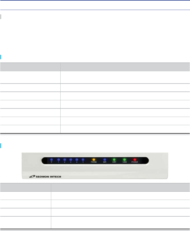
LED Indicator Function
PWR Power Supply status (On at Power ON)
LAN ON when connected to PC, Flashing at communication
PHONE ON when connected to Telephone, Flashing at communication
RSSI Representation WiMAX received signal strength indication(RSSI),
on when the mode was selected router.
Functional Features
LED Information
*OUSPEVDUJPOUPUIF1SPEVDU
03
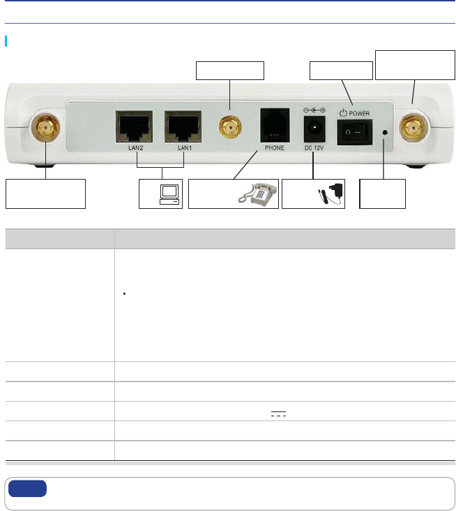
Rear Side Information
If you lost LOGIN password for router or IP address after change, use the Reset
switch to restore its original Factory Default settings.
Note
Antenna1
WiMAX Diversity
Antenna3 WiFi
Hardware
Reset
Power Switch
PC Power
Adapter
Item Details
External Antenna
Antenna1 : WiMAX Diversity
Antenna2 : WiMAX Main
Separable external antenna
User external type antenna attachable
* Antenna Classification
- 2.3G : M23
- 2.5G : M25
- 3.5G : M35
- WiFi : WiFi(Optional)
LAN PC or Hub connection
PHONE Telephone connection
DC 12V Power Adapter connection (DC 12V 2.0A)
POWER Power On/Off Switch (Switch between On/Off by pressing right or left)
RESET Restore the VoIP CPE Factory Default
Antenna1
WiMAX Diversity
TelePhone
To verify the normal operation of the router, check the following LEDs after connecting the router,
modem, and PC with a LAN cable, as follows:
LED Normal Operation Actions to take if not illuminated
PWR ON when connecting adapter Check for adapter power failure
LAN ON when cable is connected normally Check cable connection and PC power supply
PHONE On when Phone cable is connected
normally Check cable connection and Telephone
WiMAX RSSI
Represents WiMAX received signal
strength indication (RSSI), ON when in
router mode
Check that router mode is selected
$POGJHVSBUJPO
If one or more LED lights is not in “normal operation”, take the actions specified in the table.
Install a router after connecting to the network.
If normal connection between router and PC is checked, you have to set up the PC and router.
PC setup is to control network configuration for Windows 98, Windows 2000, or Windows XP to
use the Internet while the PC is connected to a router.
Router setup is to connect a router to the Internet. Please refer to the CPE Setup chapter.
04
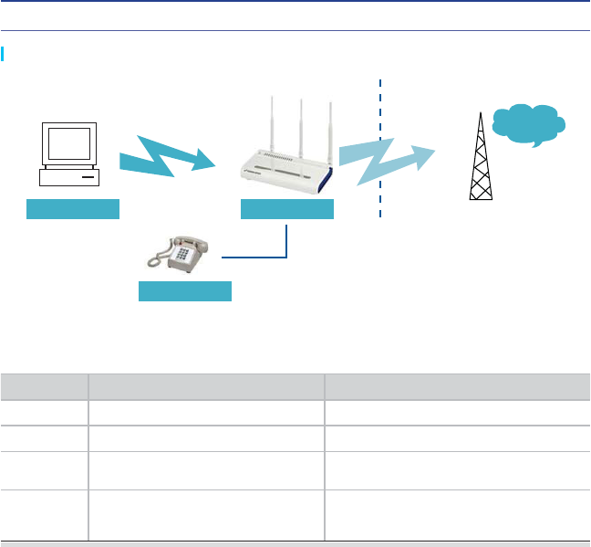
Network Configuration
Local Network External NetworkGateway
PC WiMAX
Internet
Telephone
$POGJHVSBUJPO
05
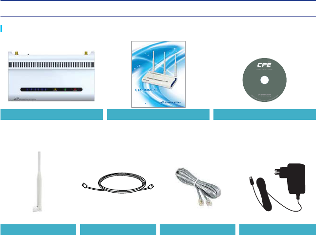
Package Contents
Main Unit User Manual CD
Antenna X 3
XXXTFPXPOJOUFDIDPLS5&-
&/+0:6#*26*5064%3&".
Adapter Telephone CableUTP Cable
06
$POGJHVSBUJPO
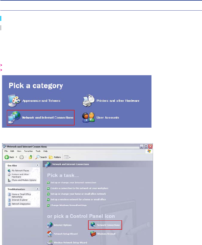
PC Configuration (Windows XP)
Click the Windows Start button, and select Settings >> Control Panel from the menu.
Double-click the “Network Connection” icon in the Control Panel.
This procedure is used to restore Windows XP’s TCP/IP setup to the default values. If Windows
has just been installed for the first time on the PC, no changes should be required, but you
should check to confirm that all values are normal according to the following.
After completing the TCP/IP setup of the PC, connect PC and CPE with a LAN cable and turn
CPE on before Windows starts up to determine whether an IP address is obtained from CPE
automatically.
Double-click the Network and Internet Connections
Double-click the Network Connection
$POGJHVSBUJPO
07
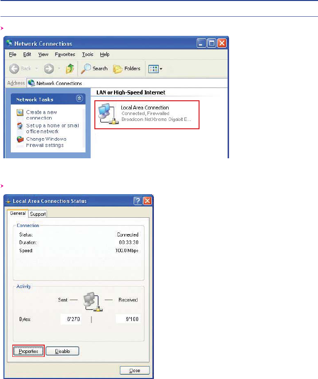
Double-click the Local Area Connection from the Network Connection list to select it.
Click “Properties” in the Local Area Connection Status window.
Double-click the Local Area Connection
Click Properties
08
$POGJHVSBUJPO
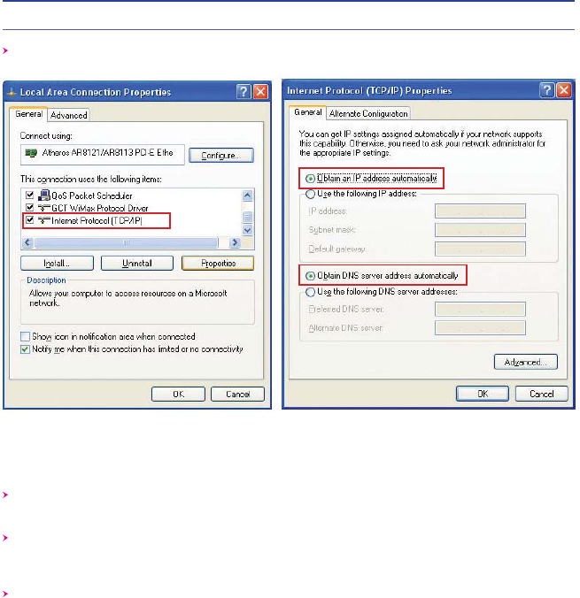
Double-click Internet Protocol (TCP/IP) to open its Properties window, and then select
“Obtain an IP address automatically” and “Obtain a DNS Server address automatically”.
After completing setup, click OK and close all of the Local Area Connection Properties
windows.
When TCP/IP setup is completed, an IP address is automatically assigned by CPE.
For automatic assignment, the PC and the CPE should be connected with a LAN cable.
If they are not connected with a cable, connect them with a LAN cable and restart the PC.
You can check the automatic IP address assignment by using the ipconfig command from the
Command Prompt.
Double-click TCP/IP Select the ‘Obtain an IP address automatically’ ,
‘Obtain a DNS Server address automatically’ and
click OK
$POGJHVSBUJPO
09
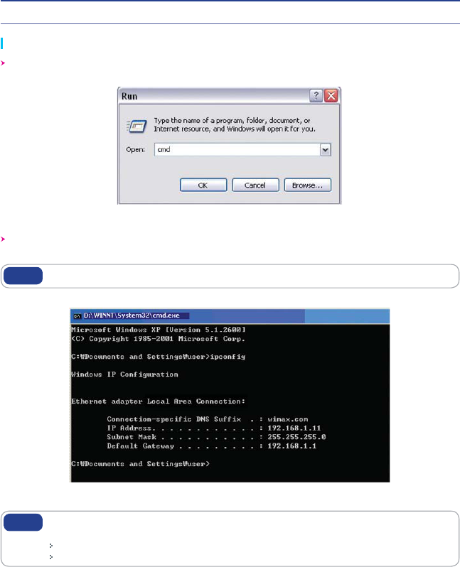
To run the Command Prompt, click the Start button at the lower left corner of the Windows
screen. Click Run, then enter “cmd” in the Open box, and click OK.
When the Command Prompt window opens, enter the “ipconfig” command to verify the IP
address, Subnet mask, and Gateway, which are automatically assigned to PC.
All PCs connected to CPE will receive their own assigned IP address.
Note
Run cmd
Verify IP address
If an IP address is not assigned, check the following, and then restart the PC and
check whether an IP address is assigned.
LAN cable connection between PC and CPE
Check TCP/IP setup details
Note
How to check your IP address
10
$1&#VJMUJO8FC4FSWFS"DDFTT
The WEB GUI is used to manage a CPE and view its current status.
You can access the web server that is built into the CPE, even when not connected to the
Internet.
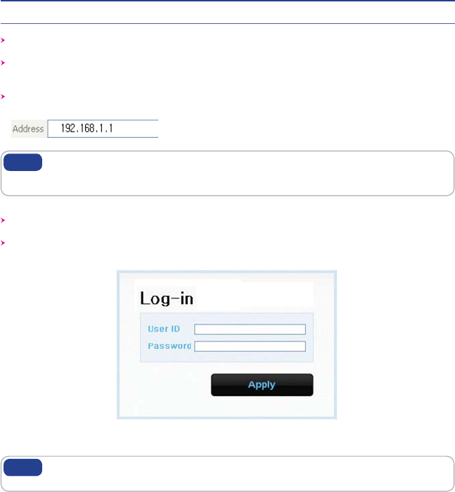
To access the web server, open Internet Explorer or your Browser and type “192.168.1.1”,
which is the IP address of CPE, in the address bar, as shown below:
If the PC is connected to the CPE but is not connected to the Internet, entering the
IP address of 192.168.1.1 in the address box will connect the PC to the CPE web
server. This function may not operate in some environments.
Note
Upon accessing the CPE, the following Login screen will be displayed.
The default user ID and password are admin, which you can change on the web server.
If you have no input activity for 1 hour, your web connection is terminated. In this
Case, please login again through the login page.
Note
ID / Password = admin / admin
$1&4FUVQPOUIFXFCQBHF
11
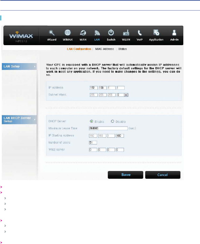
LAN (LAN Configuration)
Select “LAN” → “LAN Configuration” menu.
Configure LAN IP address
LAN IP address is used in the LAN that the CPE manages.
Configure LAN IP address in “IP Address/Subnet Mask” text boxes.
Initial Value is “192.168.1.1/255.255.255.0” and only the last byte in “Subnet Mask” box can
be modified.
Configure DHCP server
Enable DHCP server to lease IP address to the computer connecting to CPE with wired LAN.
Set Maximum lease time (in seconds), IP Starting address, Number of users and WINS
server address.
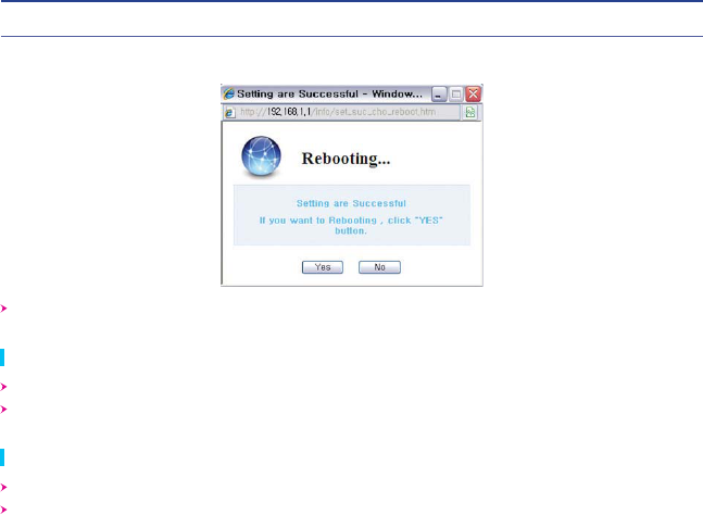
Finish setup by clicking the “Save” button. A pop-up window asking you to reboot the system
will then appear.
12
$1&4FUVQPOUIFXFCQBHF
If you have finished CPE setup and want to reboot the CPE, click “Yes” to reboot the CPE.
LAN (Status)
Select “LAN” → "Status" from the menu.
You can see the details of the LAN configuration.
Switch (Status)
Select “Switch” → “Status” from the menu.
You can see the various configurations related to Switch configuration, such as Switch mode
and several filters.
$1&4FUVQPOUIFXFCQBHF
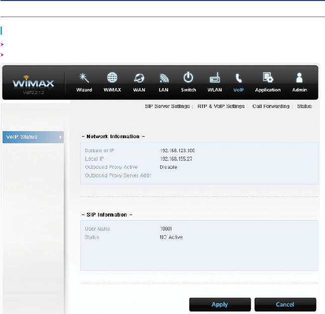
VoIP (Status)
Select “VoIP” → “Status” from the menu.
You can see the various configuration related VoIP configuration.
13
$1&4FUVQPOUIFXFCQBHF
14
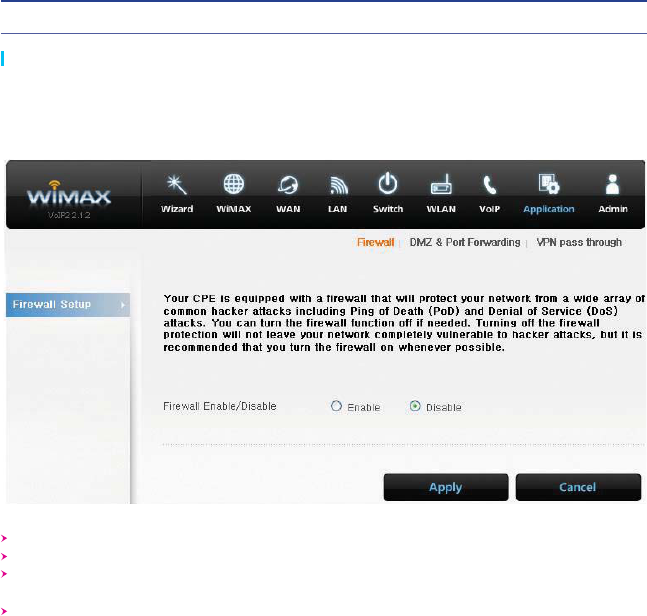
Application (Firewall)
Firewall enables you to set the CPE so that it is not affected by external hacking attempts,
including Ping Flooding or DoS. Internal LAN PCs are usually isolated/protected from external
Internet attacks even when a firewall is not used, but it is still preferable to set the firewall to ON
as much as possible. By default, the firewall is set to ON.
Select “Application” → “Firewall” from the menu.
If you want to use the Firewall function, check the “Enable” checkbox.
Finish setup by clicking the “Apply” button. A pop-up window informing you of the result will
appear.
Changed configuration is applied immediately.
15
$1&4FUVQPOUIFXFCQBHF
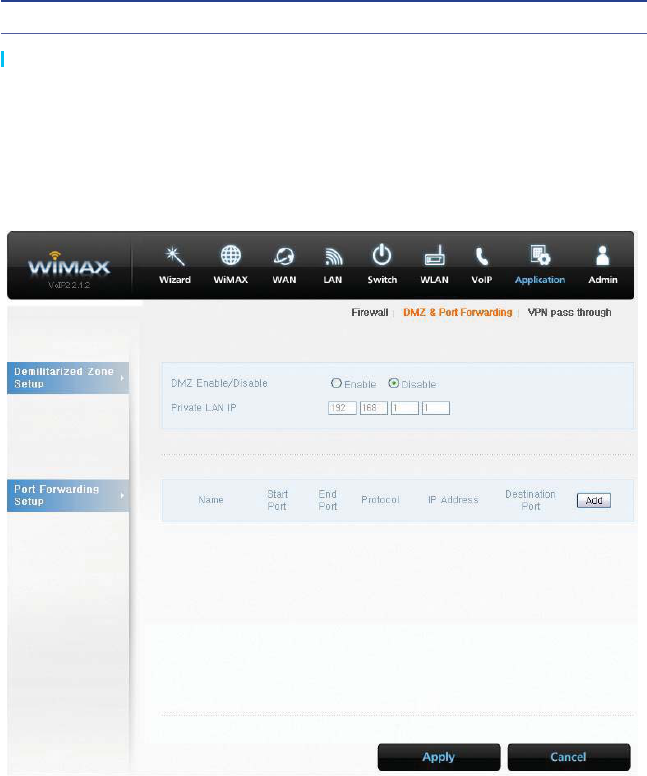
Application (DMZ & Port Forwarding)
The DMZ feature allows you to specify one computer on your network to be placed outside
of the NAT firewall. This may be necessary if the NAT feature is causing problems with an
application, such as a game or video conferencing application. Use this feature on a temporary
basis, as the computer in the DMZ is not protected from attacks by hackers.
The Port Forwarding function is used to forward incoming packets of specific TCP/IP port from
outside to the assigned PC. This function is useful if you have to use VoIP or P2P applications,
or have to operate HTTP or FTP servers from a PC in the internal LAN.
16
$1&4FUVQPOUIFXFCQBHF
Select “Application” → “DMZ & Port Forwarding” from the menu.
Configure DMZ
Select whether or not to enable the DMZ function.
Set the IP address to have all ports opened in “Private LAN IP” content.
Finish setup by clicking the “Apply” button. A pop-up window informing you of the result will
appear.
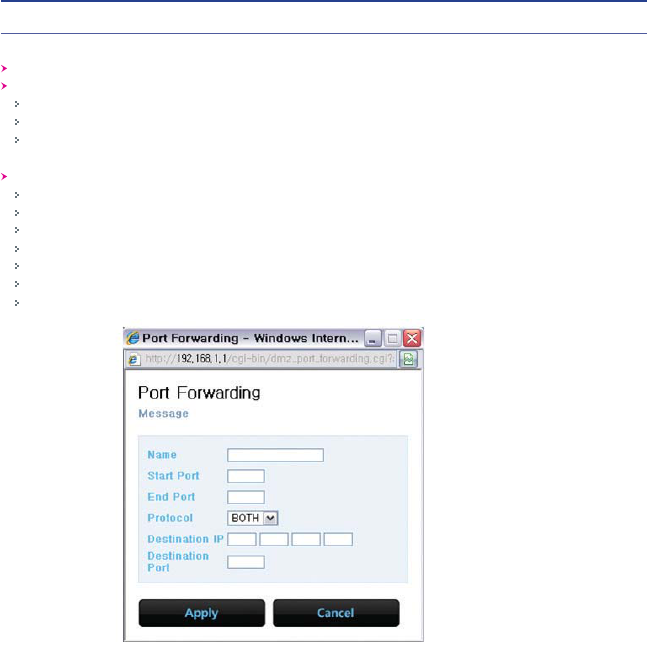
Configure Port Forwarding
The port forwarding function can be configured when DMZ is disabled.
To add Port Forwarding, click “Add”. You will then see the pop-up window for Port Forwarding.
Enter the information for Port Forwarding.
Click “Apply”.
The pop-up window will close, and added Port Forwarding is shown.
To modify/delete the existing Port Forwarding list, use the “Edit”/”Delete” button.
Changed configuration is applied immediately.
$1&4FUVQPOUIFXFCQBHF
17
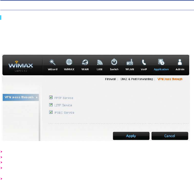
Application (VPN pass through)
The VPN (Virtual Private Network) function is used to obtain access to a security network
installed in a company or an organization via the Internet network.
If there is a VPN Server outside, and one has access to the VPN Server via the Internet
network by using CPE, this screen shows how to activate the security protocol supported by the
appropriate VPN Server.
Select “Application” → “VPN pass through” from the menu.
SWC-5x00 supports 3 types of service: PPTP, L2TP and IPSEC.
Select the type(s) of VPN pass-through to use with the checkboxes.
Finish setup by clicking the “Apply” button. A pop-up window informing you of the result will
appear.
Changed configuration is applied immediately.
$1&4FUVQPOUIFXFCQBHF
18
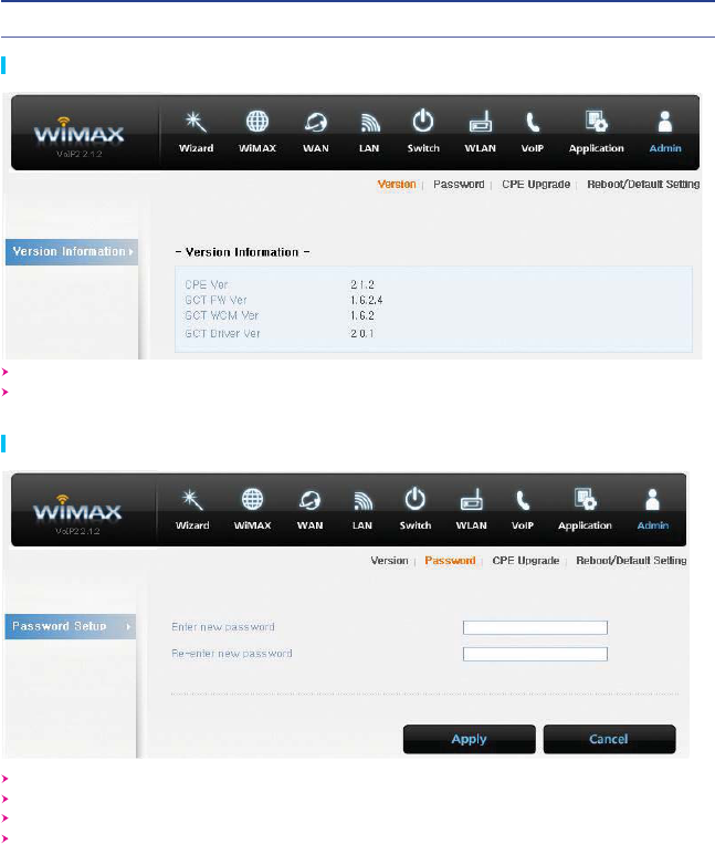
Admin (Version)
Select “Admin” → “Version” from the menu.
You can see the versions of the SWC-5x00 firmware and the Wimax firmware in use.
Select “Admin” → “Password” from the menu.
Set the Password to be given to the Administrator who manages the CPE.
Enter the new password, and re-type it to confirm.
Finish setup by clicking the “Apply” button. A pop-up window informing you of the result will
appear.
Admin (Password)
$1&4FUVQPOUIFXFCQBHF
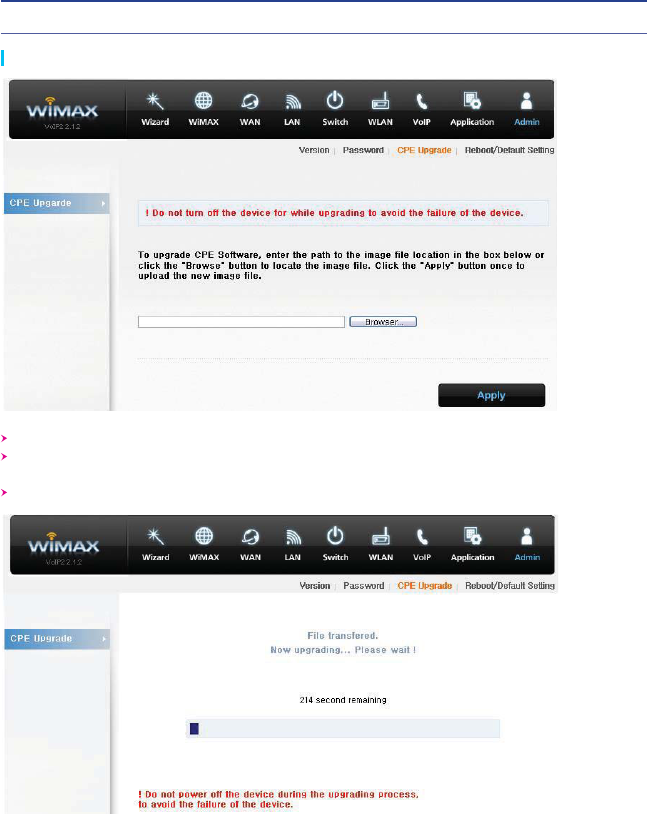
Admin (CPE Upgrade)
Select “Admin” → “CPE Upgrade” from the menu.
Input the CPE firmware path directly, or search for the firmware file by clicking the “Browser”
button.
To start the firmware update, click “Apply”.
19
$1&4FUVQPOUIFXFCQBHF
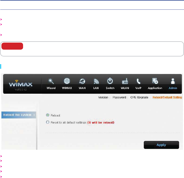
Admin (Reboot/Default Setting)
This will take several minutes, and time will vary according to the environment.
In some case, a pop-up window asking to rebuild the system will be opened due to a version
difference. If this occurs, click “Yes” to rebuild the system.
CPE is rebooted automatically after the upgrade process is complete.
To avoid failure of the CPE, do not power off the CPE during the upgrading
process.
Caution
Select “Admin” → “Reboot/Default Setting” from the menu.
Select “Reboot” to reboot the CPE.
Select “Reset to all default settings” to reboot the CPE and initialize CPE configuration.
To reboot the CPE, click “Apply”.
The CPE is rebooted automatically. This takes about 40 seconds.
20
$1&4FUVQPOUIFXFCQBHF
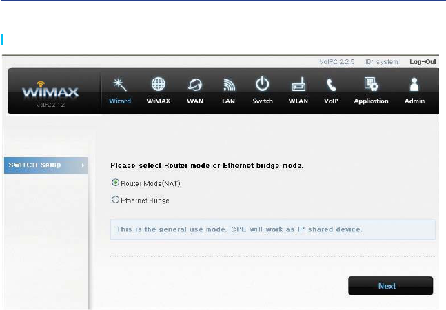
Wizard Setting
Wizard Setup is an easy tool to setup CPE. Wizard Setup take place in the following sequence:
Wizard Start → Switch mode setup → Wimax IP setup → Wimax authentication setup → Wimax
CA Certification setup → LAN IP setup → WiFi setup → Password setup → Wizard Finish.
21

22
5SPVCMF4IPPUJOH
Actions to be taken when internet is disconnected
1. Check the status of external type modem.
Check that the Link lamps of cable, modem are illuminated.
2. Check the LED status of CPE.
Check that the POWER LED is illuminated.
Check if the LEDs of WiMAX are illuminated.
For LAN port, check that the lamp of the port connected to the PC is illuminated.
3. Check the IP address of PC.
For Windows 98/ME
Click [Start] -> [Run] and enter the [winipcfg] command to open the [IP Address] window, and
then check the [IP Address].
For Windows 2000/XP
Run [Command Prompt] and enter the [ipconfig] command to check the [IP address].
4. If IP Address is not normal – Set the IP Address of the PC manually.
For Windows 98/ME
1) Execute [Run -> Control Panel -> Network], and then click Properties of [TCP/IP] for LAN
card.
2) Check [Use the assigned IP address], enter [192.168.1.100] for [IP Address] and
[255.255.255.0] for [Subnet Mask].
3) Select [Gateway] and enter [192.168.1.1] for [New Gateway], and then click [Add].
4) Select [DNS Configuration], check [Use DNS], enter any name for [Host], enter [DNS
Server Address to search], and click [Add].
5) Click [OK], click [OK] again in the [Network Properties] window, and then click [OK] from
the [Change System Setup] window to reboot the PC.

23
5SPVCMF4IPPUJOH
For Windows 2000
1) Execute [Start >> Control Panel >> Network and Dial-UP Connections],
double-click [Local Area Connection], and click [Properties].
2) Click Properties of [Internet Protocol (TCP/IP)] among Components.
3) Click [Use the following IP address].
4) Enter [192.168.1.100] for [IP Address], [255.255.255.0] for [Subnet Mask],
and [192.168.1.1] for [Default Gateway].
5) Click [Use the following DNS Server Address].
6) For [Basic Setup DNS Server], enter the communication company server of each country.
7) Click [OK]. Click [OK] again in the [Local Area Connection Properties] window.
For Windows XP
1) [Start >> Control Panel >> Network and Internet Connection],
double-click [Local Area Connection], and click [Properties].
Click Properties of [Internet Protocol (TCP/IP)] among Components.
2) Click [Use the following IP address].
3) Enter [192.168.10.100] for [IP Address], [255.255.255.0] for [Subnet Mask],
and [192.168.1.1] for [Default Gateway].
4) Click [Use the following DNS Server Address].
5) For [Basic Setup DNS Server], enter the communication company server of each country.
6) Click [OK]. Click [OK] again in the [Local Area Connection Properties] window.
For MAC OS
1) Execute [“apple” icon >> System setup >> Internet & Network >> Network >> Ethernet].
2) Select “manual” for IP Configuration.
3) Enter [192.168.1.100] for [IP Address], [255.255.255.0] for [Subnet Mask],
and [192.168.1.1] for [Router].
4) For [DNS Server], enter the communication company server of each country.
5) Click [Apply].
5. Run [MS-DOS] or [Command Prompt] and then perform PING Test with [192.168.1.1]
A message [Reply from 192.168.1.1: bytes=32 time=1ms TTL=64] should appear when
running [ping 192.168.1.1] command. If the result of the Ping test does not arrive properly,
please contact the Customer Support Center.

24
0QFSBUJOH*OGPSNBUJPO
Temperature Range and power rating for the SWC-5x00W
Operating temperature for the units is 0Ⳅ ~ 40Ⳅ
Power Rating AC for the SWC-5x00W
110-240V ~ 50/60Hz 0.6A Max
7KLVGHYLFHFRPSOLHVZLWKSDUWRI)&&5XOHV2SHUDWLRQLVVXEMHFWWRWKHIROORZLQJWZRFRQGLWLRQV
7KLVGHYLFHPD\QRWFDXVHKDUPIXOLQWHUIHUHQFHDQG
7KLVGHYLFHPXVWDFFHSWDQ\LQWHUIHUHQFHUHFHLYHG,QFOXGLQJLQWHUIHUHQFHWKDW
PD\FDXVHXQGHVLUHGRSHUDWLRQ
0RGLILFDWLRQVQRWH[SUHVVO\DSSURYHGE\WKHSDUW\UHVSRQVLEOHIRUFRPSOLDQFHFRXOGYRLG
WKHXVHU¶VDXWKRULW\WRRSHUDWHWKHHTXLSPHQW
7KLVHTXLSPHQWKDVEHHQWHVWHGDQGIRXQGWRFRPSO\ZLWKWKHOLPLWVIRUD&ODVV%GLJLWDOGHYLFH
3XUVXDQWWRSDUWRIWKH)&&5XOHV7KHVHOLPLWVDUHGHVLJQHGWRSURYLGHUHDVRQDEOHSURWHFWLRQ
DJDLQVWKDUPIXOLQWHUIHUHQFHLQDUHVLGHQWLDOLQVWDOODWLRQ7KLVHTXLSPHQWJHQHUDWHVXVHVDQG
FDQUDGLDWHUDGLR)UHTXHQF\HQHUJ\DQGLIQRWLQVWDOOHGDQGXVHGLQDFFRUGDQFHZLWKWKHLQVWUXFWLRQV
PD\FDXVHKDUPIXOLQWHUIHUHQFHWRUDGLRFRPPXQLFDWLRQV+RZHYHUWKHUHLVQRJXDUDQWHHWKDW
LQWHUIHUHQFHZLOOQRWRFFXULQDSDUWLFXODULQVWDOODWLRQ,IWKLVHTXLSPHQWGRHVFDXVHKDUPIXOLQWHUIHUHQFH
WRUDGLRRUWHOHYLVLRQUHFHSWLRQZKLFKFDQEHGHWHUPLQHGE\WXUQLQJWKHHTXLSPHQWRIIDQGRQ
WKHXVHULVHQFRXUDJHGWRWU\WRFRUUHFWWKHLQWHUIHUHQFHE\RQHRUPRUHRIWKHIROORZLQJPHDVXUHV
ƒ5HRULHQWRUUHORFDWHWKHUHFHLYLQJDQWHQQD
ƒ,QFUHDVHWKHVHSDUDWLRQEHWZHHQWKHHTXLSPHQWDQGUHFHLYHU
ƒ&RQQHFWWKHHTXLSPHQWLQWRDQRXWOHWRQDFLUFXLWGLIIHUHQWIURPWKDWWRZKLFKWKHUHFHLYHULVFRQQHFWHG
'XULQJWUDQVPLWWHURSHUDWLRQLQRUGHUWRPHHW5)0D[LPXPSHUPLVVLEOH([SRVXUH6DIHW\
*XLGHOLQHVDPLQLPXPGLVWDQFHRIFPVKDOOEHPDLQWDLQHGEDWZHHQDQWHQQDDQGSHUVRQQHO
&(
+HUHE\6(2:21,17(&+/7'GHFODUHVWKDWWKLVPRGHOVLVLQFRPSOLDQFHZLWKWKHHVVHQWLDO
UHTXLUHPHQWVDQGRWKHUUHOHYDQWSURYLVLRQVRIGLUHFWLYH(&

25
1SPEVDU8BSSBOUZBOE$VTUPNFS4VQQPSU
Product Warranty
Product Name: Gateway Modem Model Name: SWC-5x00W
This product comes with a one-year warranty, which is described in the following:
Contents of Warranty Rules
1. Equipment for Warranty: SWC-5x00W
2. Warranty Period : 1 year
3. Free Repair Service or Replacement
If a defect or failure of the product occurs within the warranty period.
4. Warranty does not cover the following.
If a defect or failure of the product occurs after the expiration of the warranty period.
If a defect or failure of the product occurs due to a natural disaster, such as fire, flood,
and lightning.
If a defect or failure of the product occurs due to any unauthorized alteration or repair to the
product.
If a defect or failure of the product occurs due to other actions of the consumer.
26
8BSSBOUZ*OGPSNBUJPO
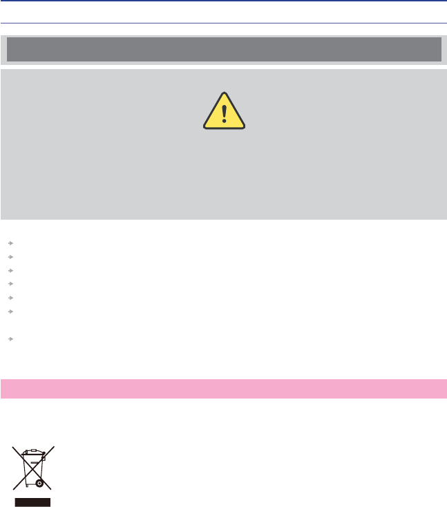
Safety Precaution
When minor injury or product damage can
occur from violation of the following directions.
Caution
Do not put any object on the product.
Avoid heating devices.
Never disassemble, repair or redesign the product.
Be careful not to let any alien particle get inside the product.
Do not leave the Product near a magnet or direct magnetic field.
If you use the product at a location where static electricity is severe, it can cause malfunction
to the product.
Do not put any metallic object (coin, hair pin) or flammable object inside the product or drop
the product.
WEEE Notice
The purpose of this Directive is, as a first priority, the prevention of WEEE, and in addition,
to promote the reuse, recycling and other forms of recovery of such wastes so as to reduce
disposal.
The WEEE logo on the product or on its box indicates that this product must
not be disposed of or dumped with your other household waste.
You are liable to dispose of all your electronic or electrical waste equipment
by relocating over to the specified collection point for recycling of such
hazardous waste.
27
8BSSBOUZ*OGPSNBUJPO
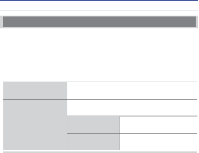
Quality Warranty
This product is manufactured through strict quality control and inspection process.
In case of a problem in normal condition, the product will be repaired free of charge during
the warranty period.
If the service applies to "charged After-sale Service type" during the warranty period,
service fee will be charged.
When requesting for repair, you must provide the warranty.
Keep the warranty in a safe location because it is not reissued.
1.
2.
3.
4.
5.
Purchase date
Quality warranty period
Seller
Telephone number
Consumer
1(one) year
Name
Address
Telephone number
E-mail
In the following cases, service fee can be charged as charged After-sale Service type.
- In case of issue due to inappropriate use.
- In case of issue after repair by uncertified service center.
- In case of issue after disassembling Product by consumer.
- In case of problem by natural disaster such as fire, earthquake etc.