SEOWON INTECH SWU11 WiMAX Modem User Manual
SEOWON INTECH CO., LTD. WiMAX Modem Users Manual
UserManual.wiki
>
SEOWON INTECH
>
SWU11 User Manual
Users Manual
Navigation menu
Upload a User Manual
Namespaces
Wiki Guide
HTML
PDF
Info
Views
User Manual
Discussion / Help
Navigation
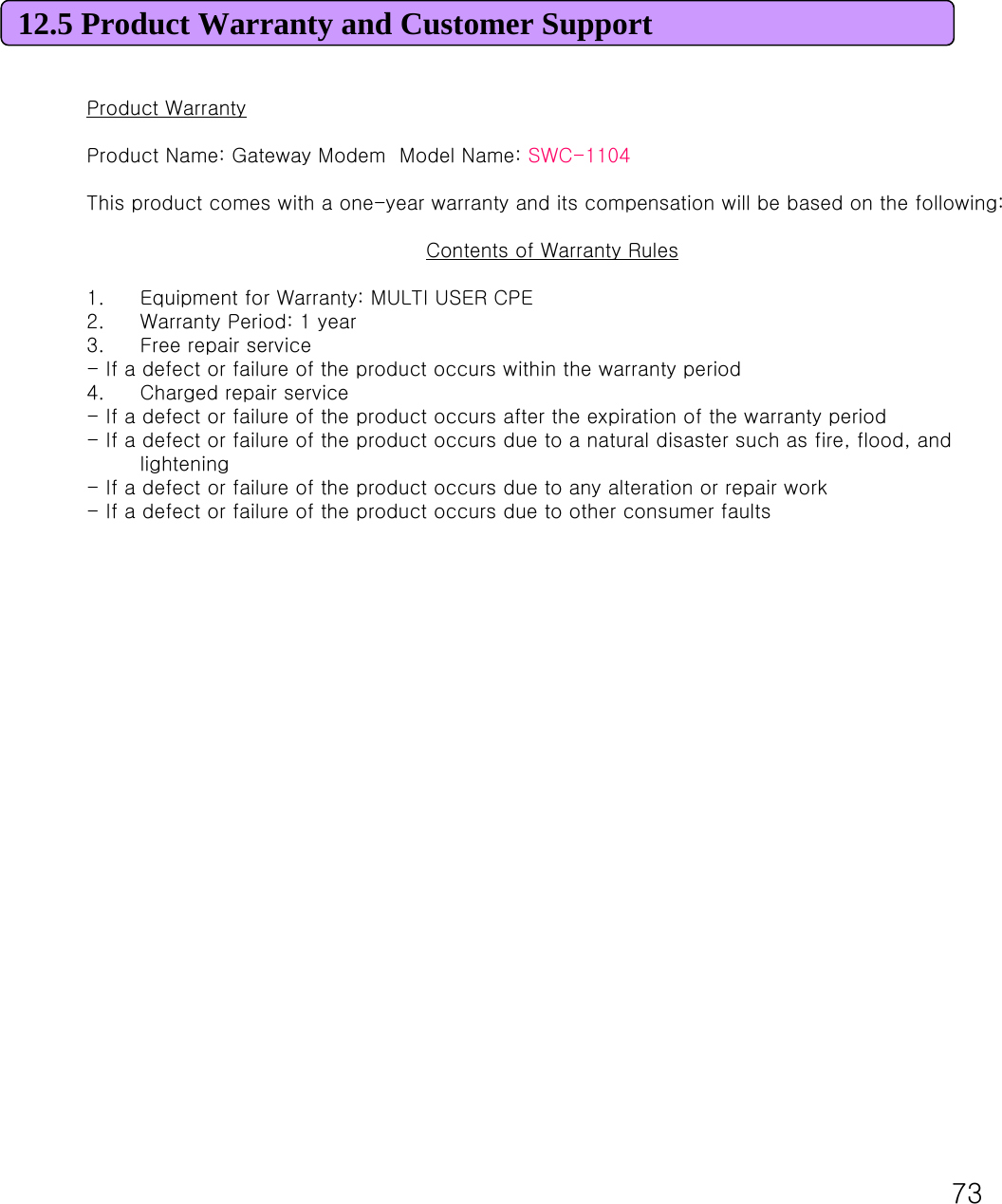
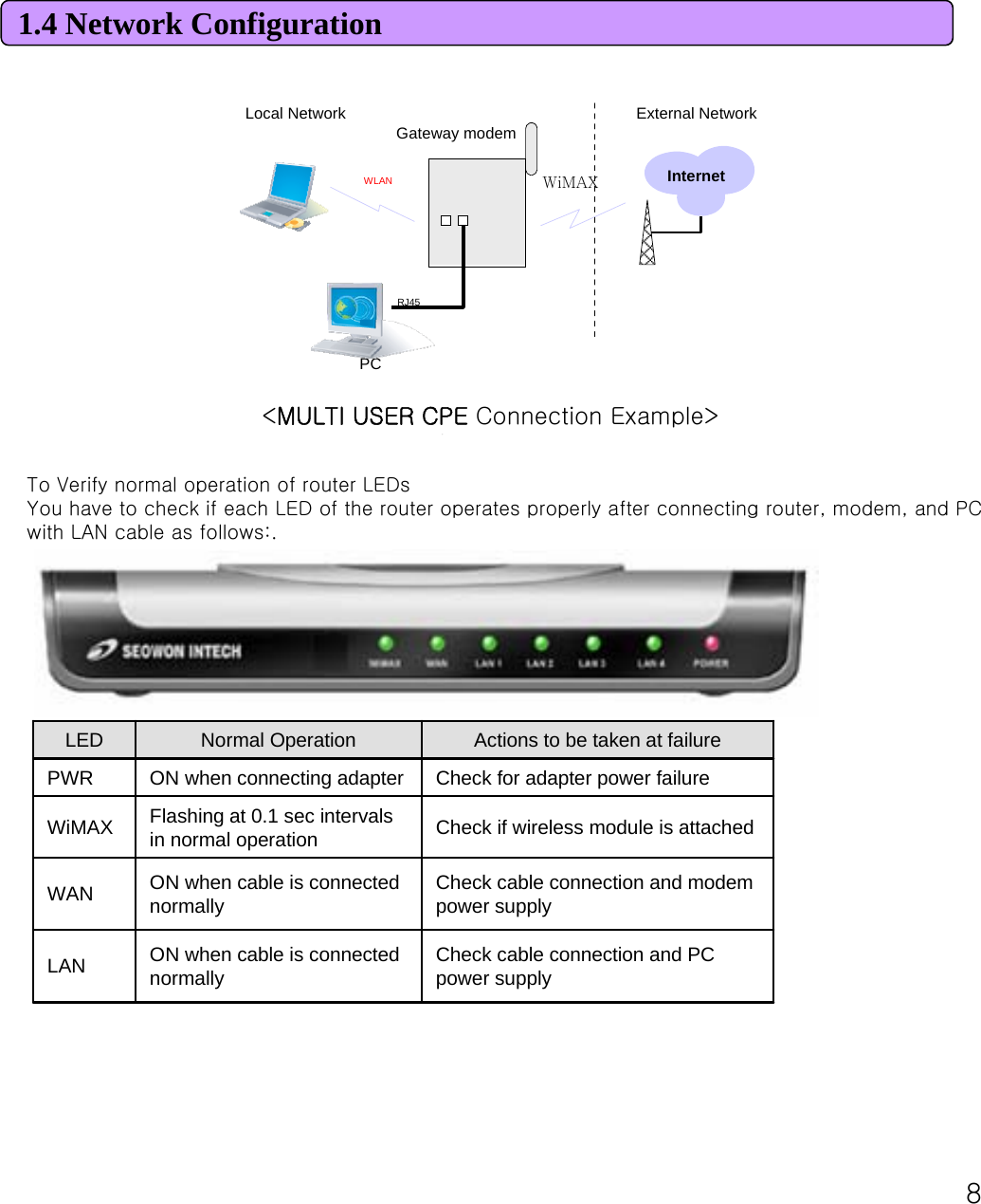
![71.3 Description of Product FunctionMULTI USER CPE Rear SideDescriptionSystem ResetRESETPC or Hub connectionLAN 1~4External modem connection portWAN Power Adapter connection (DC 7.5V ~ 24V)DC IN Power On/Off Switch (On/Off by pressing right or left) Power S/WANT1: WiMAX DiversityANT2: WiMAX MainSeparable external antennaUser external type antenna attachable* Antenna Classification-5: 2.5GHzExternal AntennaDetailsItem[Note] If you lost LOGIN password for router or IP address after change, use the Reset switch to restore its original Factory Default settings.](https://usermanual.wiki/SEOWON-INTECH/SWU11/User-Guide-947970-Page-7.png)
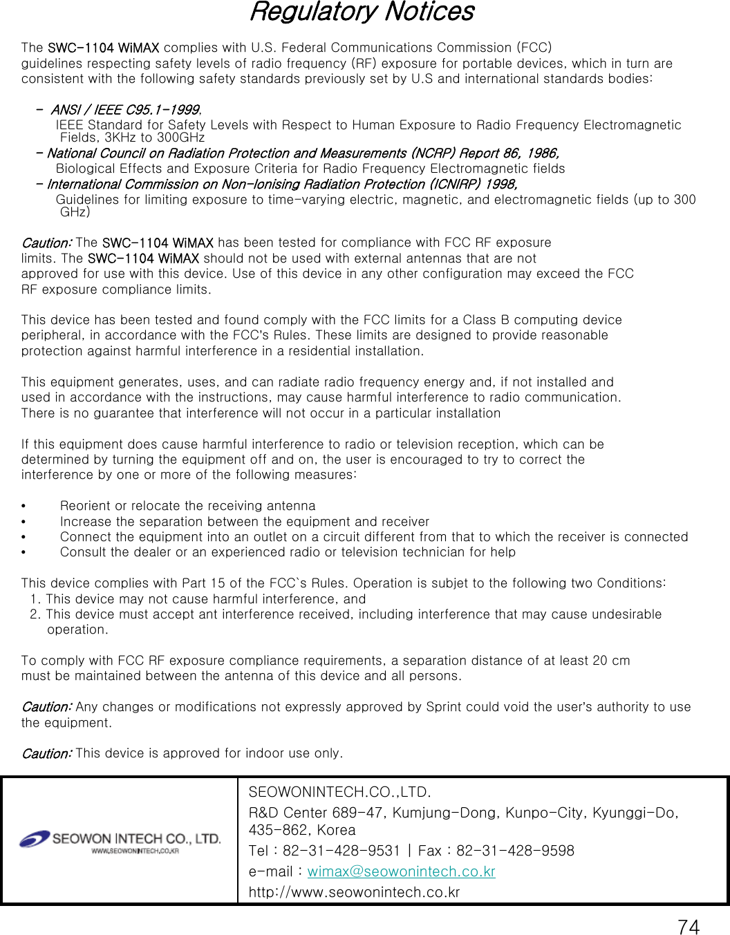
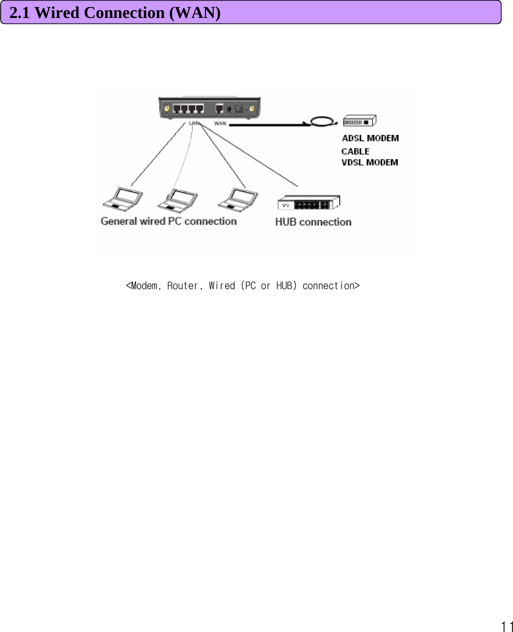
![102. Multi User CPE Connection2.1 Wired Connection (WAN)1) Connecting Power AdapterConnect Power Adapter to AC terminal and then connect DC connector.When turning the power switch on, only Power LED keeps lighting up and all other lamps are turned ON for about 1 second and then OFF.When booting is completed, WiMAX lamps of MULTI USER CPE are flashing at about 0.1 secintervals.Always use the rated adapter of the product for a router. If not, it may cause malfunction and damage.2) Connecting ModemConnect the LAN terminal of modem (varies depending on modem) and the WAN terminal of MULTIUSER CPE.(In case of LAN mode Internet service, there is no modem but a LAN line from wall outlet. Connect the LAN line of wall outlet to the WAN terminal.)In case of internal modem, contact to the Internet service provider so as to replace it with an external type modem.When LAN line is normally connected, the WAN lamp is ON, and flashing if there is any communication.3) Connecting PCConnect the LAN card of PC or the LAN port of motherboard to the router LAN 1~4.When connected normally, the appropriate LAN lamp is turned ON. 4) Connecting Hub- To connect more than 4 PCs, do through Hub. - Connect the LAN port of HUB and one of the router LAN 1~4. - If connected normally, the LAN lamp and the lamp of the port connected to HUB are turned ON. [Note] * If connected to the UP-LINK of HUB, you cannot use the next port to UP-LINK. * HUB and router connect to one port only. They cannot be used for more than 2 connections. * Since this product has the cable auto sensing function, direct (straight) and cross cables can be freely used when connecting LAN or WAN port.](https://usermanual.wiki/SEOWON-INTECH/SWU11/User-Guide-947970-Page-10.png)

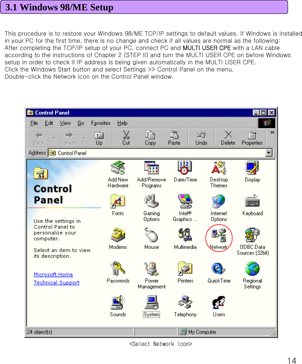
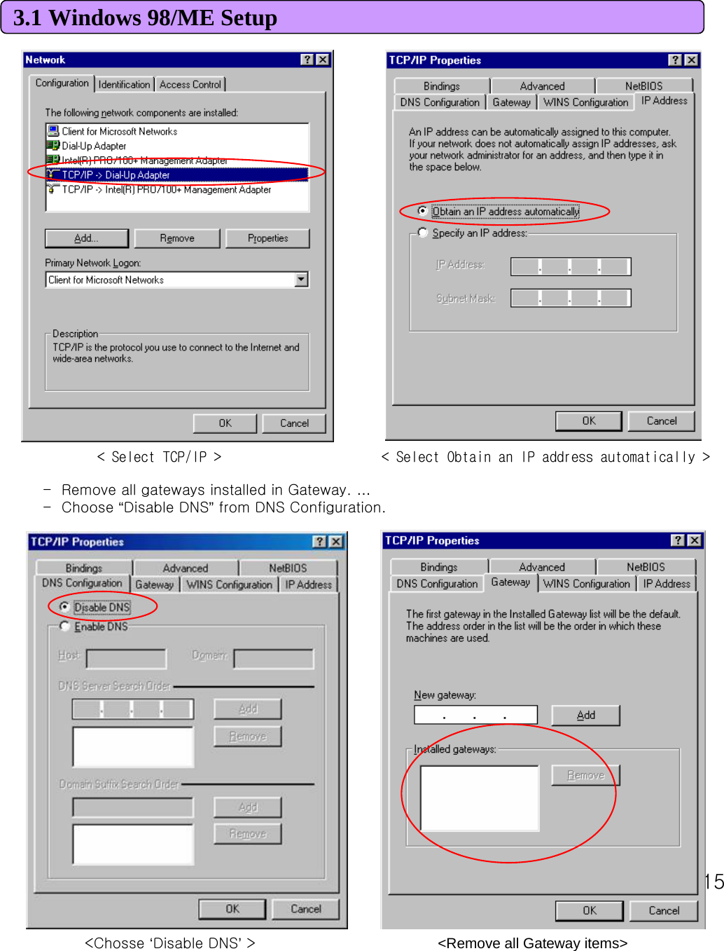
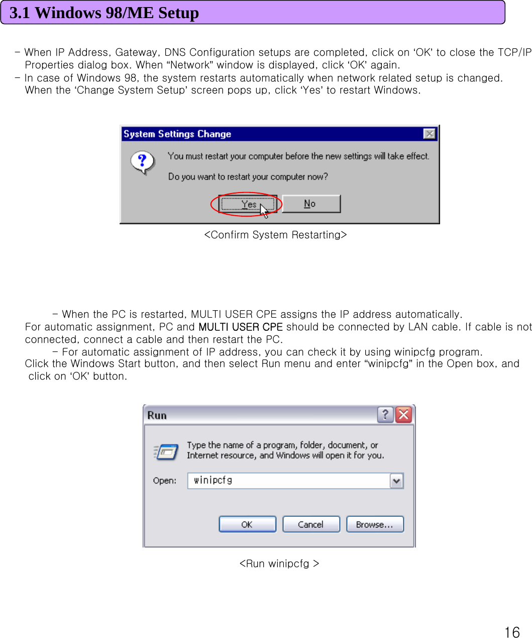
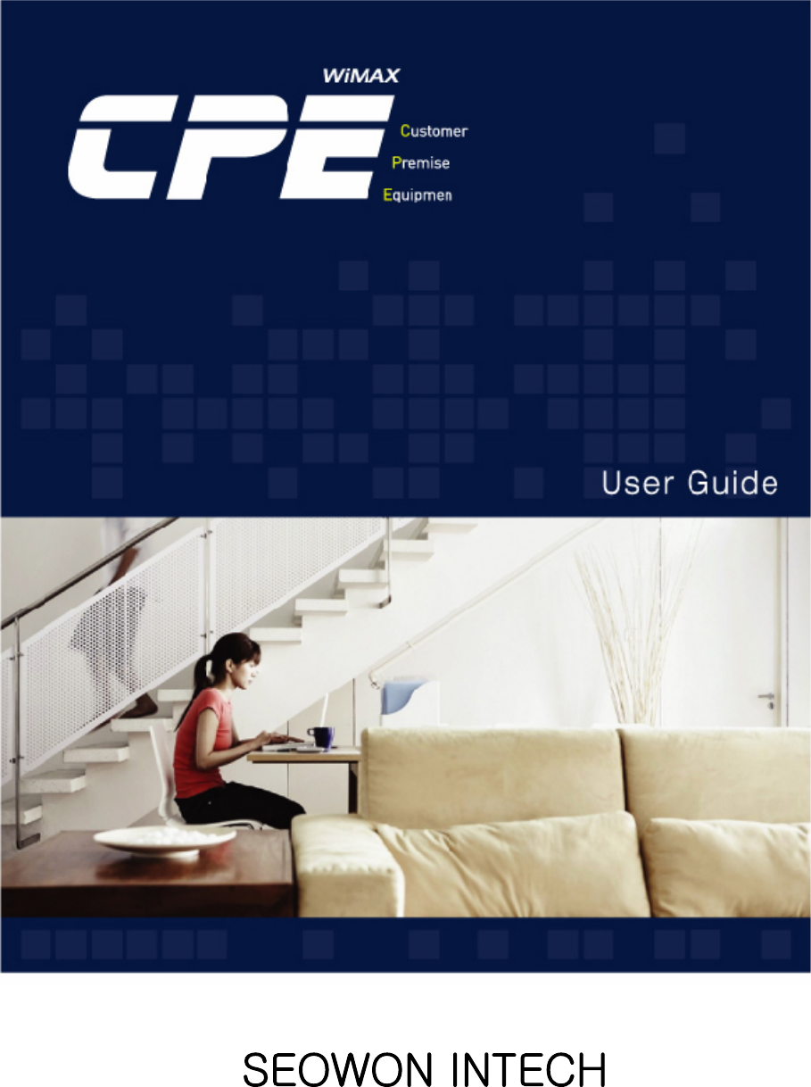
![173.1 Windows 98/ME SetupSelect LAN card adapter used by connecting the router from the winipcfg IP Configuration window (Select NDIS 5.0 or the appropriate LAN card. Do not select PPP adapter) to check if the IP address of your PC is assigned to the value between 192.168.1.10 and 192.168.1.60 automatically. If you cannot see other LAN card than PPP adapter being used, you have to reinstall a LAN card driver. (Select LAN Card, click “Disconnect”and then “All Create”or “All Update”button to check IP assignment.) [Note] All PCs connected to MULTI USER CPE will get each of assigned IP addresses respectively. 00-52-00-01-19-A2192.168.1.10255.255.255.0192.168.1.1SelectSelect LAN Card: Select NDIS 5.0 or the appropriate LAN cardAdapter Address: Different values on each adapter, ignorableIP Address: 192.168.1.10 ~ 192.168.1.60Subnet Mask: 255.255.255.0Default Gateway: 192.168.1.1[Note] If the IP address of PC is not assigned automatically, check the following and restart PC to check if the IP address is assigned. - Connect a LAN cable between PC and MULTI USER CPE- Check TCP/IP setup detailsTo use Internet after completion of PC setup, refer to Chapter IV and set the WAN port of MULTI USER CPE to connect to the Internet. Since Internet connection setup is made by MULTI USER CPE, you don’t need to set up in all PCs but do just once. < Check IP Address >](https://usermanual.wiki/SEOWON-INTECH/SWU11/User-Guide-947970-Page-17.png)
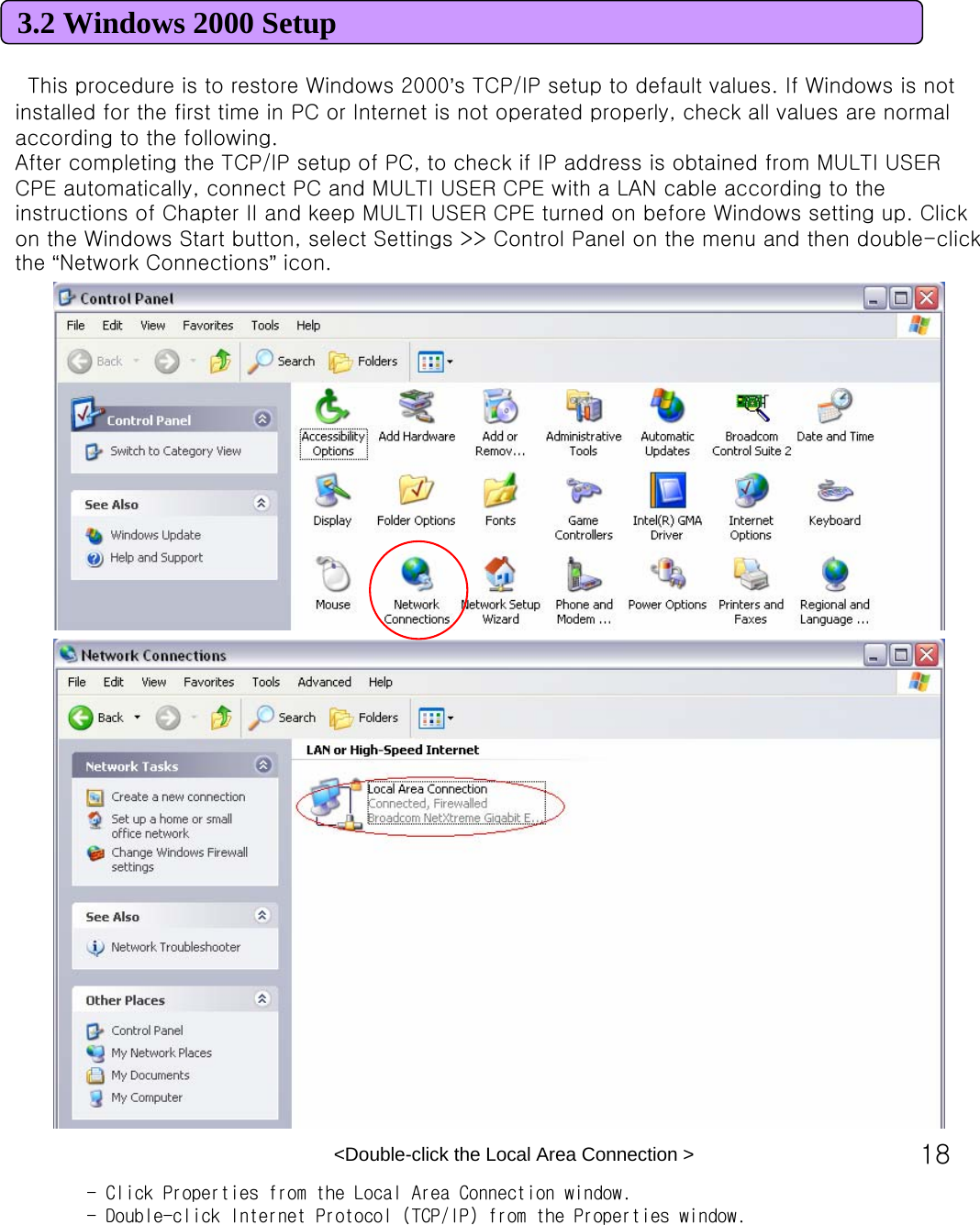
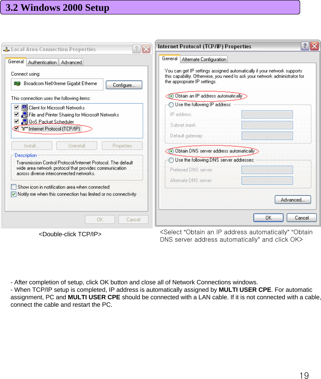
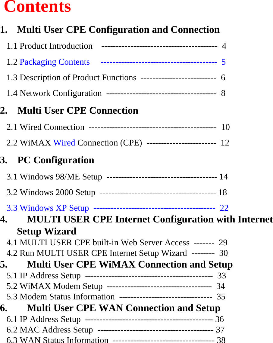
![203.2 Windows 2000 Setup- You can check the automatic IP address assignment by using the ipconfig command from Command Prompt.- To run the Command Prompt, click the Start button on the lower left corner of Windows screen and click Run to enter “cmd”in the Open box, and then click OK button. When the Command Prompt runs, enter the “ipconfig”command to verify IP address, Subnet mask, and Gateway, which are automatically assigned to PC.[Note] All PCs connected to MULTI USER CPE will get each of assigned IP addresses respectively.<Run cmd>](https://usermanual.wiki/SEOWON-INTECH/SWU11/User-Guide-947970-Page-20.png)
![213.2 Windows 2000 SetupIP Address: 192.168.1.10~60 Subnet Mask: 255.255.255.0 Default Gateway: 192.168.1.1 [Note] If IP address is not assigned normally, check the following and restart PC so as to check if the IP address is assigned.- LAN cable connection between PC and MULTI USER CPE- Check TCP/IP setup details- Whether or not to remove ADSL access programTo use Internet after completion of PC setup, refer to Chapter IV and set the WAN port of MULTI USER CPEto connect to the Internet. Since Internet connection setup is made by router, you don’t need to set up in all PCs but do just once. <Verify IP address>](https://usermanual.wiki/SEOWON-INTECH/SWU11/User-Guide-947970-Page-21.png)
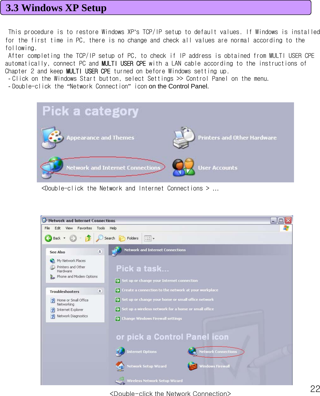
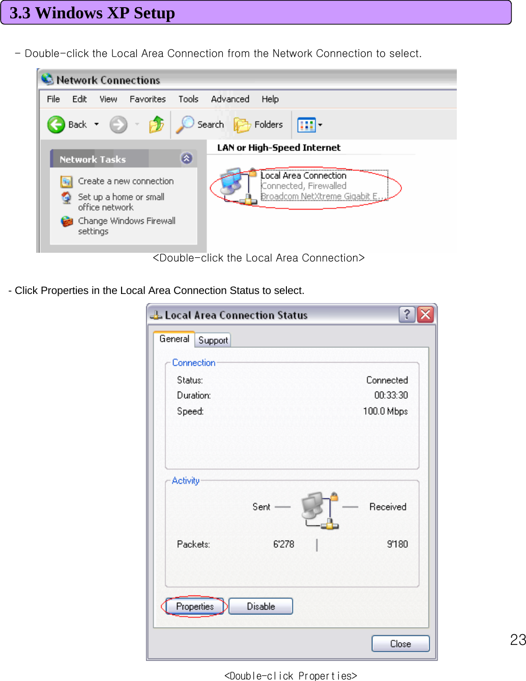
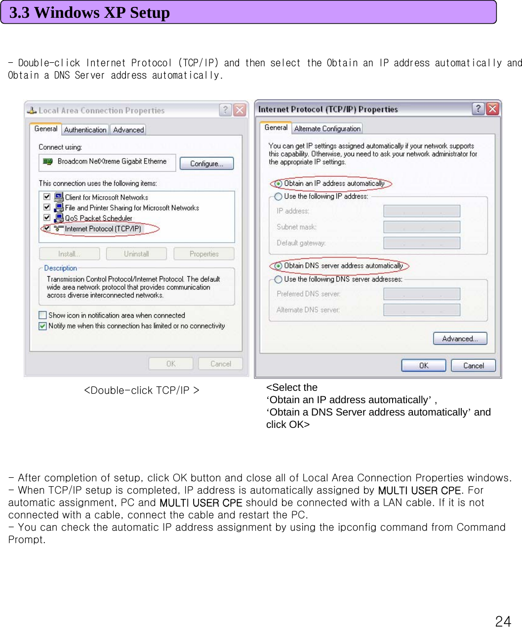
![253.3 Windows XP Setup- To run the Command Prompt, click the Start button on the lower left corner of Windows screen and click Run to enter “cmd”in the Open box, and then click OK button. - When the Command Prompt runs, enter the “ipconfig”command to verify IP address, Subnet mask, and Gateway, which are automatically assigned to PC. [Note] All PCs connected to MULTI USER CPE will get each of assigned IP addresses respectively. IP Address: 192.168.1.10 ~ 60Subnet Mask: 255.255.255.0 Default Gateway: 192.168.1.1 [Note] If IP address is not assigned normally, check the following and restart PC so as to check if the IP address is assigned. -LAN cable connection between PC and MULTI USER CPE-Check TCP/IP setup details-Whether or not to remove ADSL access program (Broadband Connection icon)<Run cmd><Verify IP address>](https://usermanual.wiki/SEOWON-INTECH/SWU11/User-Guide-947970-Page-25.png)
![263.3 Windows XP SetupTo use Internet after completion of PC setup, refer to Chapter IV and set the WAN port of MULTI USER CPEto connect to the Internet. Since Internet connection setup is made by router, you don’t need to set up in all PCs but do just once. [Note] How to remove Internet access program when using ADSL.(Windows 98/ME, 2000) In case of PPPoE connection mode, automatic running of access program while on Internet Explorer can cause no appearance of setup screen. In this case, always delete the connection icon that executes the program automatically.For users of PPPoE mode ADSL, if the access program is not removed from the Add/Remove Programs or it is hard to find the program, click Tools on Internet Explorer >> Internet Option >> Connection and then “remove”the icon of ADSL and VPN (Virtual Private Network) Connection. <In case ADSL connection icon exists> <All telephone line icons are removed>](https://usermanual.wiki/SEOWON-INTECH/SWU11/User-Guide-947970-Page-26.png)
![273.3 Windows XP Setup[Note] How to remove the Windows XP broadband connection when using ADSL.Double-click the Start on Desktop –Control Panel –Network Connections to pop up. From the Network Connections window, right-click on the icon added in Broadband to “delete”. If not deleted, right-click on “Disconnect”and “delete”the icon. <PPPoE connection icon in Broadband>](https://usermanual.wiki/SEOWON-INTECH/SWU11/User-Guide-947970-Page-27.png)
![29You can access to the web server built in the MULTI USER CPE, even in the environment not connected to Internet.To access to the web server, run Internet Explorer and input 192.168.1.1, the address of MULTI USER CPE, in the address box as shown below. 4.1 Access to the Multi User CPE Built-in Web Server[Note] If PC is connected to the MULTI USER CPE normally but not connected to Internet, only inputting the address of 192.168.1.1 in the address box correctly can lead to be connected to the MULTI USER CPE web server. This function may not operate in specific environment. Accessing to the…MULTI USER CPE, the following Login screen will be displayed. The default user ID and password are admin, which you can change on the web server.](https://usermanual.wiki/SEOWON-INTECH/SWU11/User-Guide-947970-Page-29.png)
![5911. WCM11.1 Software Installation•Caution before Installtion. -Connect the USB modem to your PC before installing the software. When the modem is connected. “New Hardware Detect”window appears. Then User may ignore this window or click “Cancel”button. - If you have previous WCM Version, uninstall it first (See figure below)•Connect the USB Modem to your PC before installing the software.1) Please insert WiMAX modem CD into CDROM Drive. When the Setup Menu Screen appears. Click SEOWON WCM Execution to install Driver and WCM 2) Click [SEOWON WCM] to continue. Click [Next] button](https://usermanual.wiki/SEOWON-INTECH/SWU11/User-Guide-947970-Page-59.png)
![6011. WCM11.1 Software InstallationInstall Driver. Wait for 1~2 minite. Click [Next] button.2) Verification : Select [Start] –[Control] –[System] –[Hardware] –[Window device Manager].You may verify the driver in device manager.(See figure below)Clicik [Install] button. Click [Finish] button.](https://usermanual.wiki/SEOWON-INTECH/SWU11/User-Guide-947970-Page-60.png)
![6111. WCM11.2 How to use WCM1) Running WCM. - To start WiMAX Connection manager. Select [Start] > [Program] > [SEOWON] > [SEOWON WIMAX] > [SEOWON WIMAX CM] - Click icon. 2) Display Window. - Main Screen User can see the antenna icon about Antenna sensitivity, button about Connection / Disconnection / Menu / Help Icon.Connected](https://usermanual.wiki/SEOWON-INTECH/SWU11/User-Guide-947970-Page-61.png)
![6211. WCM11.2 How to use WCM-Help MenuClick [Help Menu] then popup menu appears. 1) Contact Us2) Seowonintech Info : User can see to the seowonintech Homepage3) Engineer Mode : Appear Engineer mode.](https://usermanual.wiki/SEOWON-INTECH/SWU11/User-Guide-947970-Page-62.png)
![6311. WCM11.2 How to use WCM- Main ScreenClick [MENU] then popup menu appears. 1) Connection : When user clicks this button, user can connect to internet byAuto and Windows start* Auto Connection : When WCM is launched, internet is connected Automatically* Window Start Connection : When Windows OS is launched, WCM is executedAutomatically.2) Connection Info : Click [Connection Info] in MENU. User can see Connection / Network / Program Information.](https://usermanual.wiki/SEOWON-INTECH/SWU11/User-Guide-947970-Page-63.png)
![6411. WCM11.2 How to use WCM- Switch from Main Display into Tray IconClick [ _ ] Icon in Main Display, WCM will be running in Tray mode. - Switch from Tray Icon into Main DisplayClick [ x ] Icon in Main, WCM will be moving to Tray mode.and In Tray, Click WCM Icon, Main Display will be appearedConnectedConnectedConnected](https://usermanual.wiki/SEOWON-INTECH/SWU11/User-Guide-947970-Page-64.png)
![6511. WCM11.2 How to use WCM3) WiMAX Connection - Click [Connected] in Main Screenand then “Connecting”Message will appearWhen WiMAX is connected successfully following figure will appearIP obtaining…Connected](https://usermanual.wiki/SEOWON-INTECH/SWU11/User-Guide-947970-Page-65.png)
![6611. WCM11.2 How to use WCM4) WiMAX Disconnection - If Click [Disconnected] button in Main Screen, the state of WCMis Stand-by modeStand byConnected](https://usermanual.wiki/SEOWON-INTECH/SWU11/User-Guide-947970-Page-66.png)
![6711. WCM11.2 How to use WCM5) WiMAX Exit - If Click [Disconnected] button in Main Screen, the state of WCMis Stand-by modeProgram exit in Main Screen. Click [Exit] in [MENU]Program Exit in Tray MenuClick the right button of mouse in Tray icon, Popup menu appears. ThenSelect [Exit].](https://usermanual.wiki/SEOWON-INTECH/SWU11/User-Guide-947970-Page-67.png)
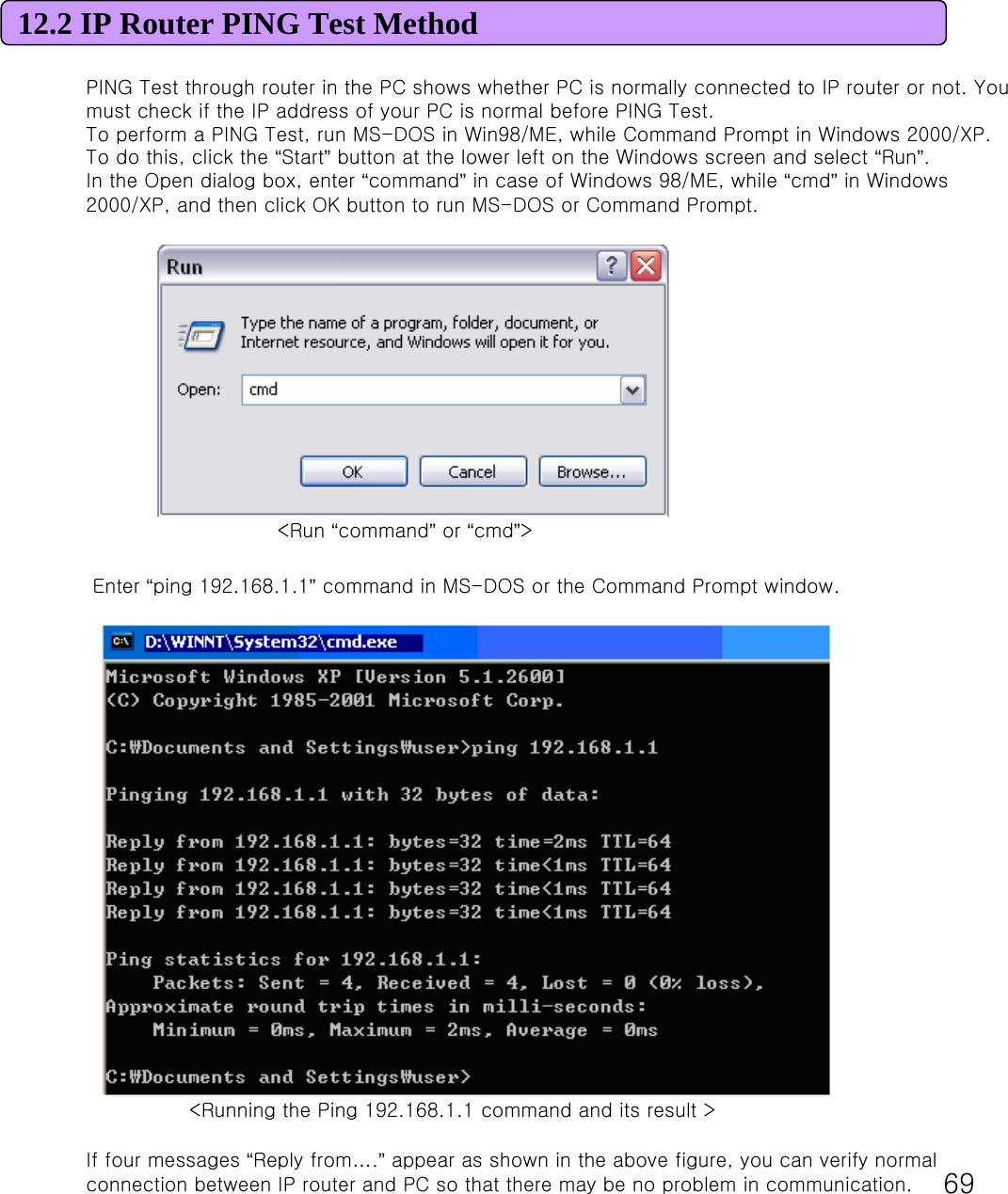
![7112.4 Actions to be taken when internet is disconnected1. Check the status of external type modem. : Check if Link lamps of cable, VDSL, ADSL modem is turned ON. 2. Check the LED status of MULTI USER CPE. 1) Check if POWER LED is turned ON.2) Check if WAN lamp is turned ON.3) Check if LEDs of WiMAX are turned ON.4) Among No. 1, 2, 3, 4 LAN ports, check if the lamp of the port connected to PC is turned ON.3. Check the IP address of PC. 1) In case of Windows 98/ME, click [Start] -> [Run] and enter the [winipcfg] command to pop up the [IP Address] window, and then check the [IP Address].2) In case of Windows 2000/XP, run [Command Prompt] and enter the [ipconfig] command to check the [IP address]. 4. If IP Address is not normal –Set the IP Address of PC manually. If IP Address is normal –Go to 5.1) In case of Windows 98/ME① Execute [Run -> Control Panel -> Network] and then click Properties of [TCP/IP] for LAN card. ② Check [Use the assigned IP address], enter [192.168.1.100] for [IP Address] and [255.255.255.0] for [Subnet Mask]. ③ Select [Gateway] and enter [192.168.1.1] for [New Gateway], and then click on [Add] button. ④ Select [DNS Configuration], check [Use DNS], enter any name in [Host], enter [DNS Server Address to search], and click [Add] button. ⑤ Click [OK], and click [OK] again on the [Network Properties] window, and then click [OK] from the [Change System Setup] window to reboot the PC. 2) In case of Windows 2000① Execute [Start -> Control Panel -> Network and Dial-UP Connections], double-click [Local Area Connection], and click [Properties].Click Properties of [Internet Protocol (TCP/IP)] among Components. ② Click [Use the following IP address]. ③ Enter [192.168.1.100] for [IP Address], [255.255.255.0] for [Subnet Mask], and [192.168.1.1] for [Default Gateway]. ④ Click [Use the following DNS Server Address]. ⑤ For [Basic Setup DNS Server],enter communication company server of eachcountry.⑥ Click [OK] button. Click [OK] again in the [Local Area Connection Properties] window.](https://usermanual.wiki/SEOWON-INTECH/SWU11/User-Guide-947970-Page-71.png)
![7212.4 Actions to be taken when internet is disconnected3) In case of Windows XP① Execute [Start -> Control Panel -> Network and Internet Connection], double-click [Local Area Connection], and click [Properties]. Click Properties of [Internet Protocol (TCP/IP)] among Components. ② Click [Use the follwing IP address]. ③ Enter [192.168.10.100] for [IP Address], [255.255.255.0] for [Subnet Mask], and [192.168.1.1] for [Default Gateway].④ Click [Use the following DNS Server Address]. ⑤ For [Basic Setup DNS Server],enter communication company server of each country.⑥ Click [OK] button. Click [OK] again in the [Local Area Connection Properties] window. 5. Run [MS-DOS] or [Command Prompt] and then perform PING Test with [192.168.1.1]. A message [Reply from 192.168.1.1: bytes=32 time=1ms TTL=64] should appear when running [ping 192.168.1.1] command. If the result of Ping test may not come properly, please contact the Customer Support Center.](https://usermanual.wiki/SEOWON-INTECH/SWU11/User-Guide-947970-Page-72.png)