SES imagotag AP0002 digital network controller transceiver User Manual My
SES-imagotag GmbH digital network controller transceiver My
Contents
- 1. Product range description
- 2. Quick start guide
Product range description

Product
Specification
AP-2010
Last change: 27.03.2017

Product Specification AP-2010
Page 2 of 27
1 Introduction 4
1.1 Key Features 4
1.2 Destination countries 4
1.3 Scope of delivery 4
2 Barcode Information 5
2.1 Serial Number 5
3 Mechanical Characteristics 7
3.1 Mechanical Dimensions 7
3.2 Front, Side and Top View 7
3.3 Upper Surface 8
3.4 Side View 8
3.5 Rear View 9
4 Mounting 10
4.1 Audience 10
4.2 General Instructions 10
4.3 Instructions for the Mounting Location 10
4.4 Approachability 11
4.5 Screw of the Antenna 11
4.6 Metal Bracket for Mounting on Wall, Ceiling or T-Mounting Rail 12
4.7 Mounting on Wall or Ceiling 12
5 Electrical Specifications 15
5.1 Used Channels 15
5.2 Difference WiFi and ESL protocol 15
5.3 Cabel Specifications 15
5.4 Power Supply Specifications 16
5.5 Pinout RJ45 Ethernet 16
6 Electrical & RF Characteristics 17
6.1 General Technical characteristics 17
6.2 Power and Current Consumption 17
6.3 General Specifications 17
7 Environmental 19
7.1 Humidity and Operating Conditions 19

Product Specification AP-2010
Page 3 of 27
7.2 Storage Conditions 19
7.3 Cleaning Instructions 19
8 Packing 20
8.1 Packing Dimensions 20
8.2 Illustrations 20
8.3 Palletization 21
9 Certifications 22
9.1 Types 22
9.2 Overview 22
9.3 Applied Standards 22
9.4 Declaration 22
10 Problems which requiring maintenance or replacement of the AP-2010 24
11 Intended Use 25
12 Improper Use 26
13 Warranty 27

Product Specification AP-2010
Page 4 of 27
1 Introduction
The Access Point AP-2010 by imagotag is a network device similar to WLAN access points that
is required for communication with the imagotag electronic shelf labels (transmits price
information to the labels).
Up to 10 000 labels can be managed per access point and the self-organizing network allows
automatic roaming of labels without manual handling. The high transmission rate of the 2.4
GHz wireless technology and the intelligent task scheduling enables fast and secure updates
on imago G1 labels of all sizes.
This document is the technical specification of the Access Point AP-2010.
In the USA and Canada the AP-2010 usa/canada bundle incl. antenna with limited data
efficiency is required according to the FCC/IC regulations. This bundle has a reduced data
efficiency for label/updates/hour, for more details see label product specification.
1.1 Key Features
lManages up to 10 000 imago G1 labels of all sizes
lCovers up to 1 950 m² (depending on shop layout)
lLow power consumption – powered by PoE (Power over Ethernet) or with low power plug
lEasy configuration and monitoring
lOptimized scheduling of tasks and self-managed roaming of labels
1.2 Destination countries
The imagotag AP-2010 is currently intended for use in Europe, Canada and USA. More countries
will follow.
1.3 Scope of delivery
l1 pcs imagotag AP-2010
l1 pcs 2.4-2.5GHz 5dBi antenna
l1 pcs metal mounting
l1 pcs “caddy® clips 4G16M11“ from Erico®
l2 pcs self-locking nuts M6
May vary depending on configuration
Product Specification AP-2010
Page 5 of 27
2 Barcode Information
The AP-2010 comes with an AP-ID, P/N, MAC and S/N. The AP-ID consists of 5 decimal digits
(0-9).
Product Code: A1A001xxx
2.1 Serial Number
Depends on Producer (A)
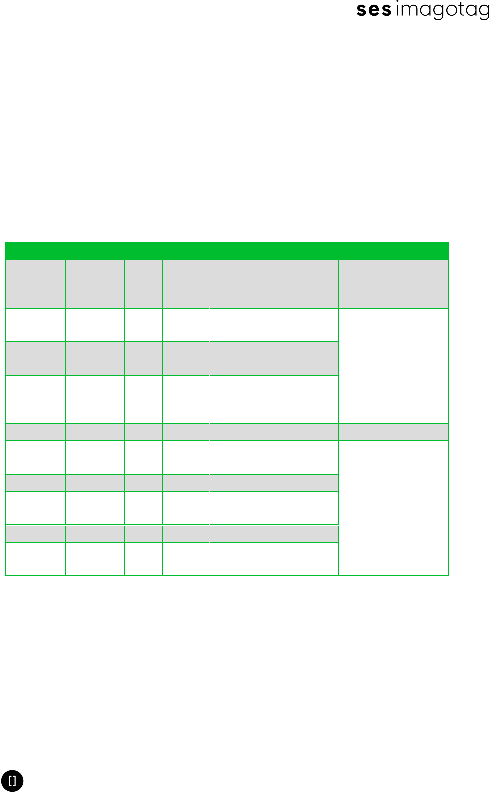
2.1.1 Producer is 01
Part Description Format Example Comment Source
A Producer 2
alpha 01
Specified by
imagotag once for
each fab
BProduct
family
3
alpha G1B
Specified by
imagotag in the
product specification
document
CProduct
version
3
alpha 301
DProduct
revision
3
alpha 001
Incremented on every
change of product
specification
- Separator “-“ - Fixed
E Internal 1
alpha B Internal
Calculated during
production
F Year 1 dec 4 4=2014, 5=2015,...
G Week 2 dec 10 Calendar week in current
year (01-53)
H Weekday 1 dec 3
I Internal 5 dec 00060 Continuous Serial
Number (Counter)
Product Specification AP-2010
Page 6 of 27
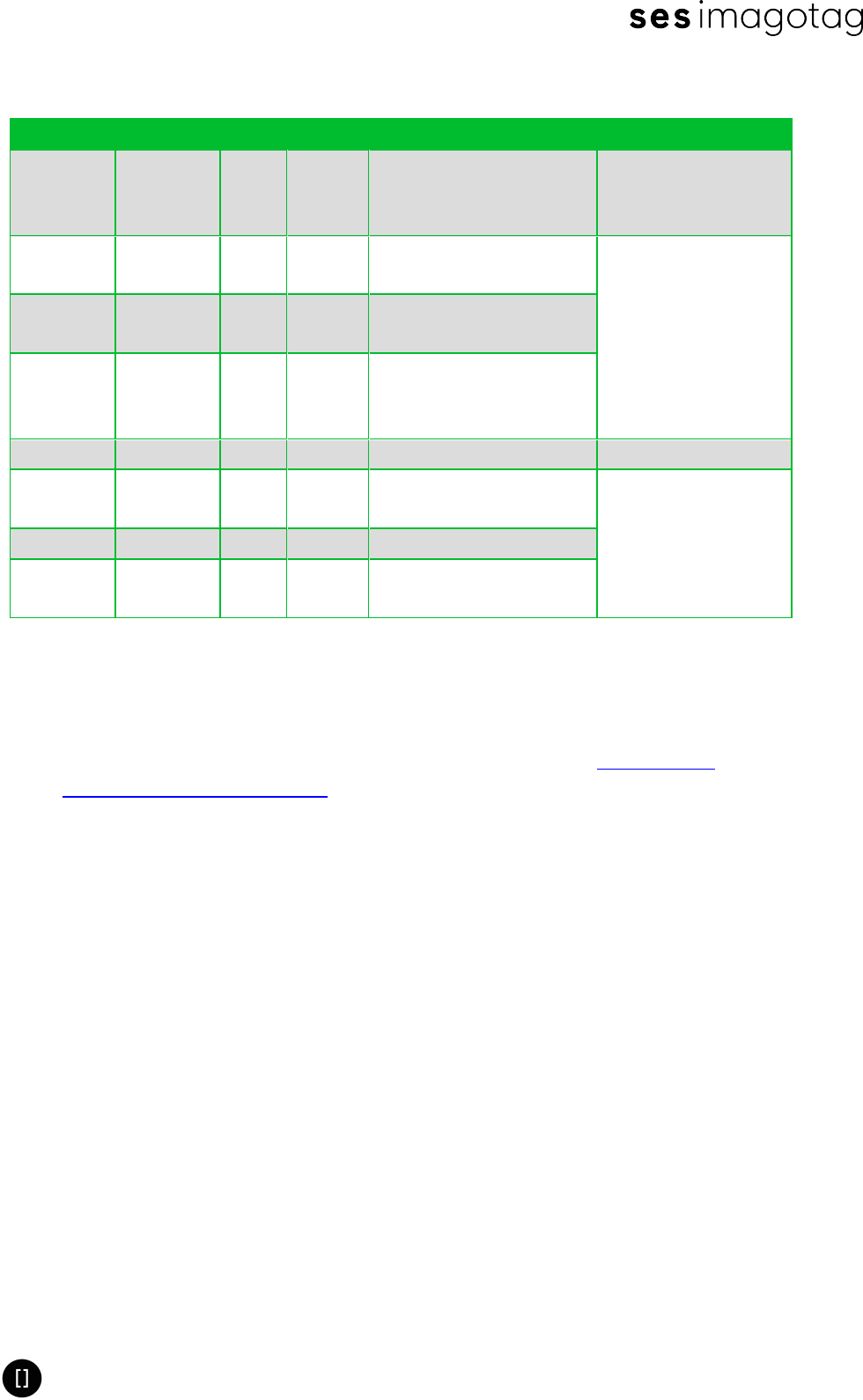
2.1.2 Producer is not 01
Part Description Format Example Comment Source
A Producer 2
alpha 02
Specified by
imagotag once for
each fab
BProduct
family
3
alpha R22
Specified by
imagotag in the
product specification
document
CProduct
version
3
alpha N01 N = with NFC
DProduct
revision
3
alpha 001
Incremented on every
change of product
specification
- Separator “-“ - Fixed
E Year 1
alpha EE=2014, A=2010,
B=2011,.. Calculated during
production
F Week 2 dec 13
G Internal 6 dec 000065 Continuous Serial
Number (Counter)
Format: AABBBCCCDDD-EFFGGGGGG
Example: 02G1B302001-E13000065
Note:
lCalendar week date is calculated according to ISO 8601 (see http://en.wiki-
pedia.org/wiki/ISO_week_date
Product Specification AP-2010
Page 7 of 27
3 Mechanical Characteristics
3.1 Mechanical Dimensions
lWith antenna:
oOutline (mm): 226 x 135 x 45
oWeight: 350 g
lWithout antenna:
oOutline (mm): 196 x 135 x 45
oWeight: 320 g
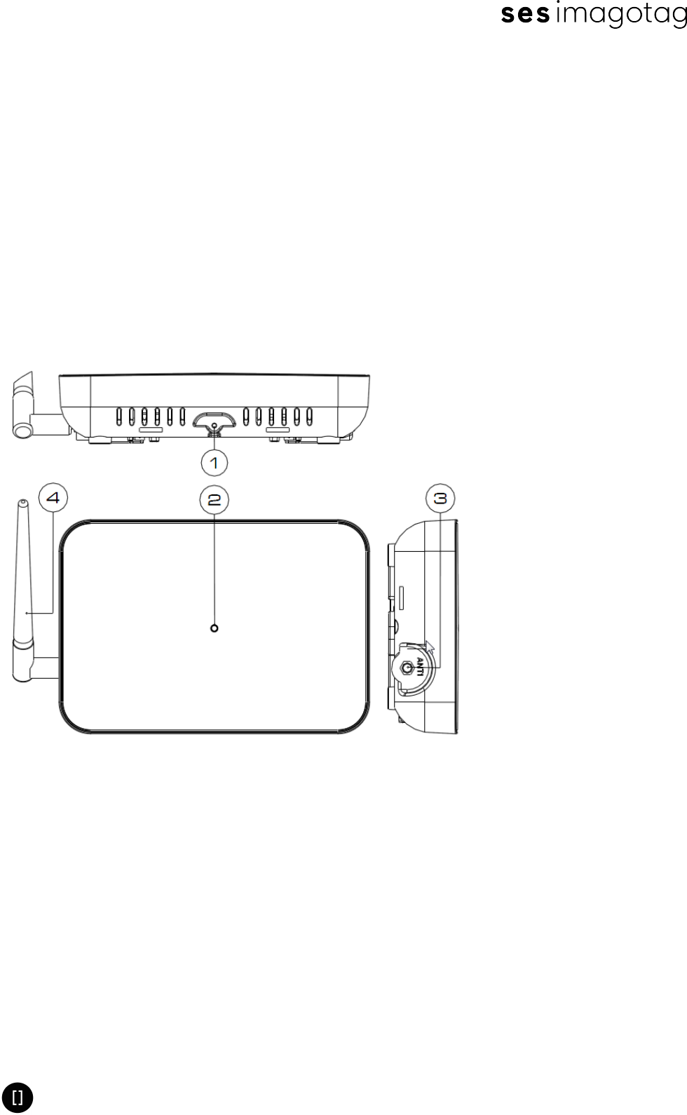
3.2 Front, Side and Top View
FIGURE 1-1: Front, side and top view of the AP-2010
1Mounting plate fixation screw-
hole
3Antenna socket
2LED 4Antenna
Product Specification AP-2010
Page 8 of 27
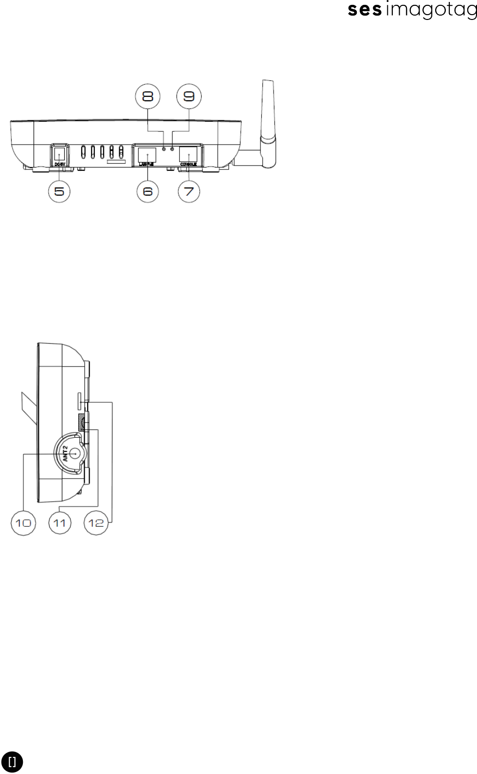
3.3 Upper Surface
FIGURE 1-2: Top view of the imagotag AP-2010
5Connection for the Power Supply 8Restart
6LAN/PoE 9Reset to Factory Settings
7Console
3.4 Side View
FIGURE 1-3: Side view of the imagotag AP-2010
10 Antenna Connector (unused) 12 Snap Connector Housing
11 Warranty Seal
Product Specification AP-2010
Page 9 of 27
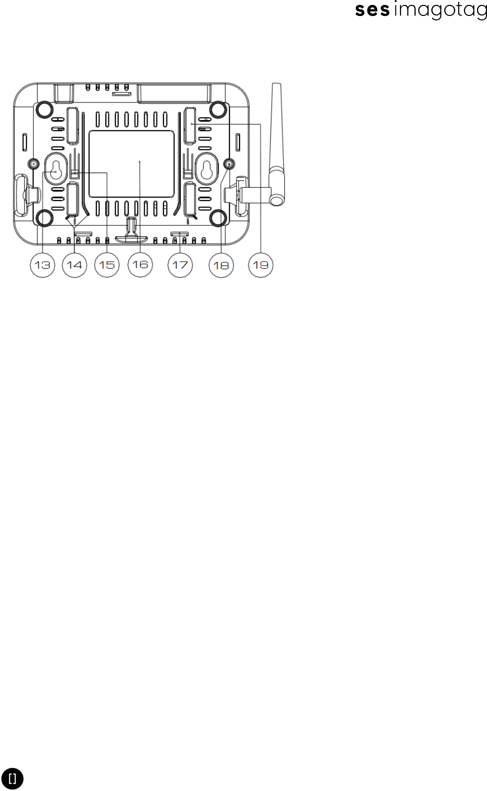
3.5 Rear View
FIGURE 1-4: Rear view of the imagotag AP-2010
13 Mounting Tab 17 Snap Connector Housing
14 Mounting Rail 18 Housing Screw
15 Locking Tab 19 Mounting Profile
16 Label

Product Specification AP-2010
Page 10 of 27
4 Mounting
4.1 Audience
The installation instructions are intended for trained electricians who can exhibit the following
qualifications:
lKnowledge of the use of tools and work instructions.
lKnowledge of the usable condition of the tool.
lKnowledge of the electrical safety instructions.
lKnowledge of the electrical building regulations.
lKnowledge of the relevant standards.
lKnowledge of assembly schedule.
4.2 General Instructions
lRead these installation instruction carefully before you connect the access point to the
power source.
lThe company imagotag GmbH assumes no liability for injury to persons or damage to the
Access Point or damage to the environment caused by improper installation or mis-
application.
lRemove jewellery such as rings, necklaces, and watches before working on the device.
lMake sure that the access point is not connected to the power source during assembly.
lDon’t work on the access point during a thunderstorm and don’t connect a cable at this
time.
lUse appropriate and tested climbing aid if you work above body height.
Complete the installation and use the ERICO products just according the
ERICO® instruction. If necessary, you will find the desired data sheets at
www.erico.com and at every ERICO customer service.
4.3 Instructions for the Mounting Location
The Access Point could be mounted on a:
lConcrete wall
lMortar wall
lT-Mounting Rail
Select the installation location for the access point carefully. Pay particular attention to the
following requirements:
lInstall the access point only in areas where the permissible environmental conditions
(see ) can be observed.
lDon’t install the access point in environmental with direct sunlight or heat source.
lMount the metal bracket for the access point on dry surfaces only.
Product Specification AP-2010
Page 11 of 27
lDon’t mount the access point on any flammable material.
lThe minimum bearing capacity of the substrate should be 5 kg.
lThe LAN cable manufacturer must be complied with the default specifications (e.g. min-
imum bend radius)
4.4 Approachability
lMount the metal bracket that the access point can easily be pushed into the metal
bracket
lMake sure that the LAN socket is easily accessible after installation.
lAfter installation the LED should be clearly visible.
lIt is important that the inner surface of the access point have sufficient air circulation.
The vents must be free to ensure good ventilation and prevent overheating.
The mounting material (e.g. screws or pegs) for securing the metal bracket on
concrete wall is not part of the scope of delivery. It must be selected by the
installer depending on the substrate itself.
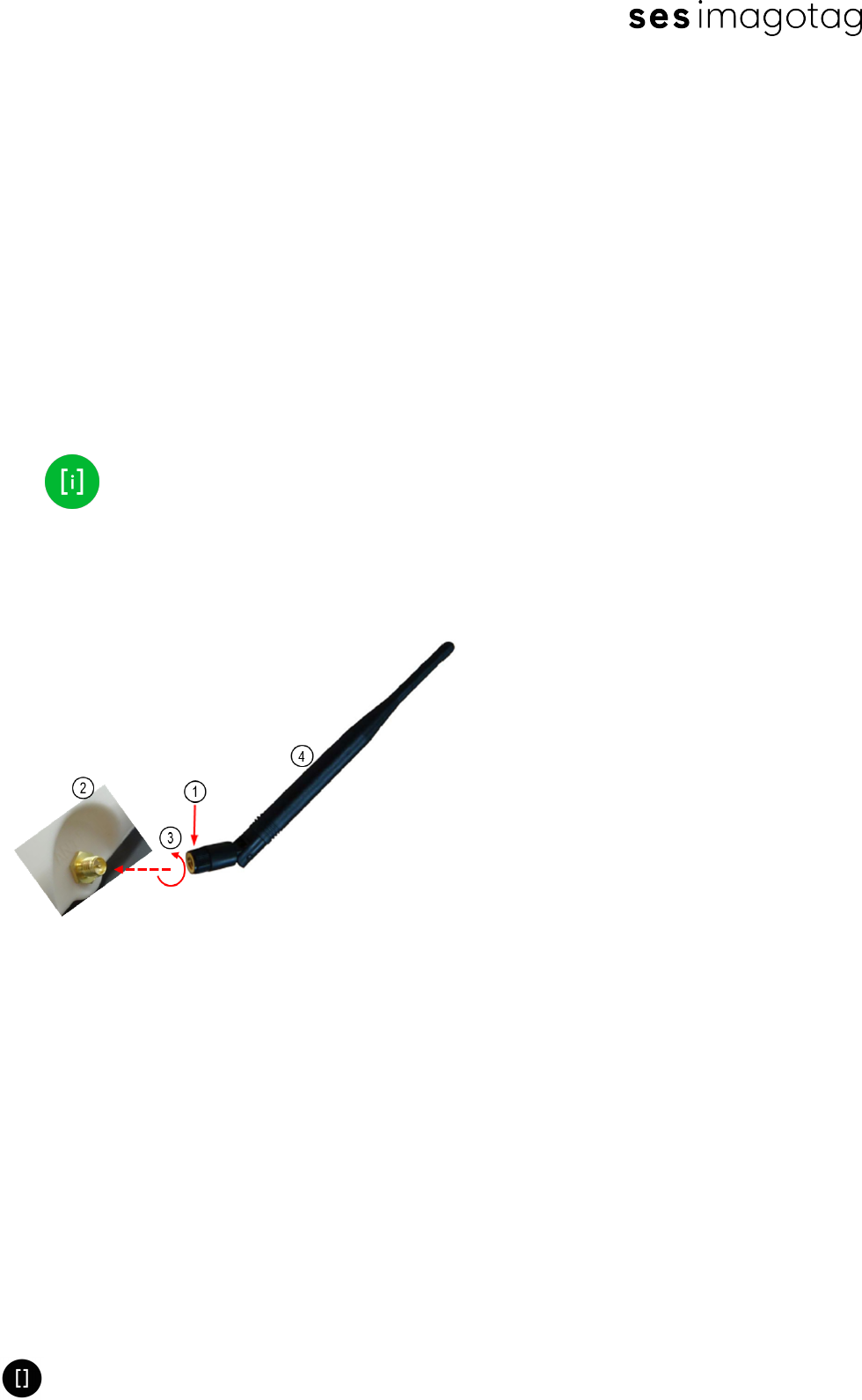
4.5 Screw of the Antenna
FIGURE 1-5: Figure 3 - Screw of the Antenna
1Front Part 3Direction of Rotation
2Connection Socket 4Rear Part (Swivelling)
Note: Screw the antenna with only the front part (1)
Product Specification AP-2010
Page 12 of 27
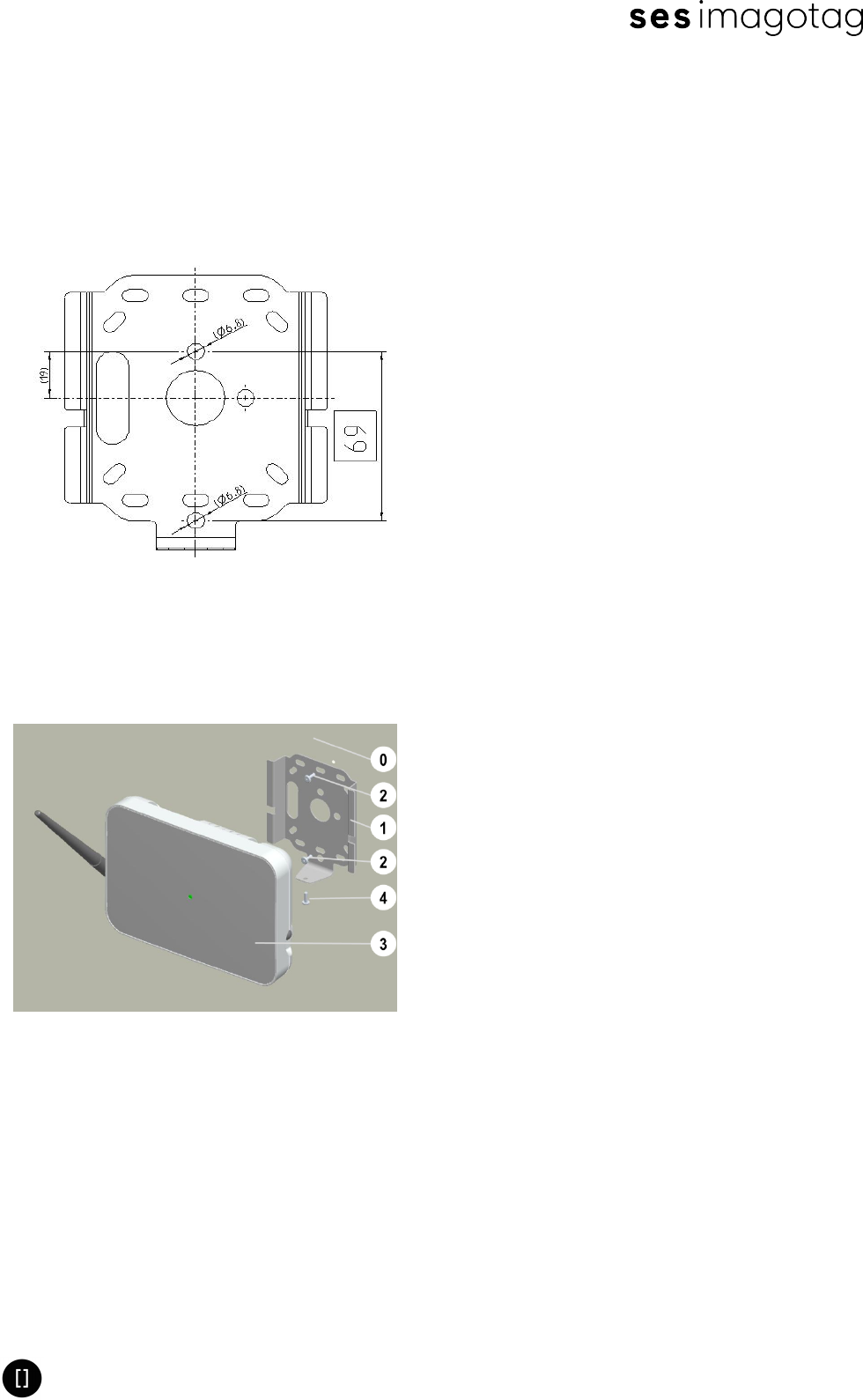
4.6 Metal Bracket for Mounting on Wall, Ceiling or T-Mounting Rail
Once the metal bracket is mounted, the AP-2010 will be mechanical connected and fixed with a
fixing screw.
FIGURE 1-6: Figure 4 - Metal Bracket for imagotag AP-2010
4.7 Mounting on Wall or Ceiling
FIGURE 1-7: Figure 5 - Wall or Ceiling Mounting (Scheme)
0Mounting Surface 3imagotag AP-2010
1Metal Bracket 4Fixation Screw
2Mounting Screw
a. Install the metal bracket to the wall or ceiling with the help of dowels and mounting
screws.
Product Specification AP-2010
Page 13 of 27
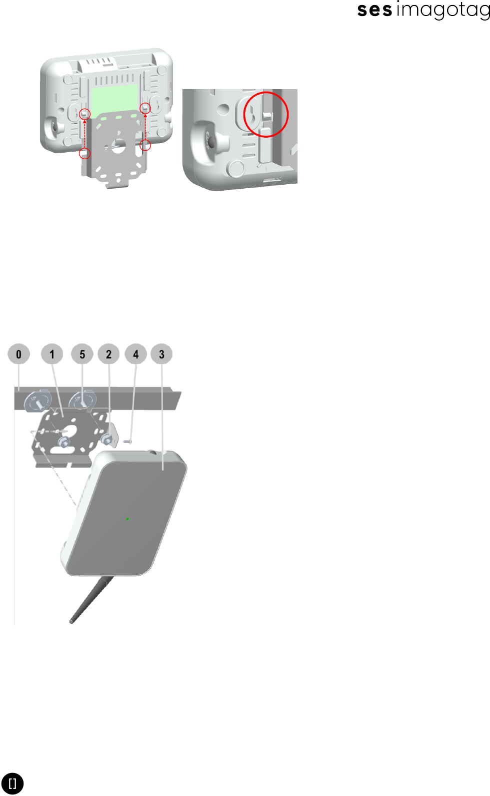
FIGURE 1-8: Figure 6 - imagotag AP-2010 Locking Tabs
b. Slide the access point to the mechanical lock of the locking tabs
c. Attach the AP-2010 with the enclosed fixation screw to the metal bracket
4.7.1 Mounting on a T-Mounting Rail
Attach the metal bracket using the included “caddy® clips” from Erico® and the enclosed, self-
locking screw nuts M6.
FIGURE 1-9: Figure 7 - Mounting an AP-2010 on a T-Mounting Rail
0T-Mounting Rail 3imagotag AP-2010
1Metal Bracket 4Fixation Screw
2Self-locking Screw Nuts M6 5ERICO® „caddy® clips“
a. Place 2 pieces of “caddy® clips” with the right distance on the T-Mounting Rail and fix it
(twist)

Product Specification AP-2010
Page 14 of 27
b. Place the metal bracket
c. Fix the Metal Bracket with 2 pieces of the self-locking screw nuts M6
d. Slide the access point to the mechanical lock of the locking tabs
e. Attach the AP-2010 with the enclosed fixation screw to the metal bracket
Product Specification AP-2010
Page 15 of 27
5 Electrical Specifications
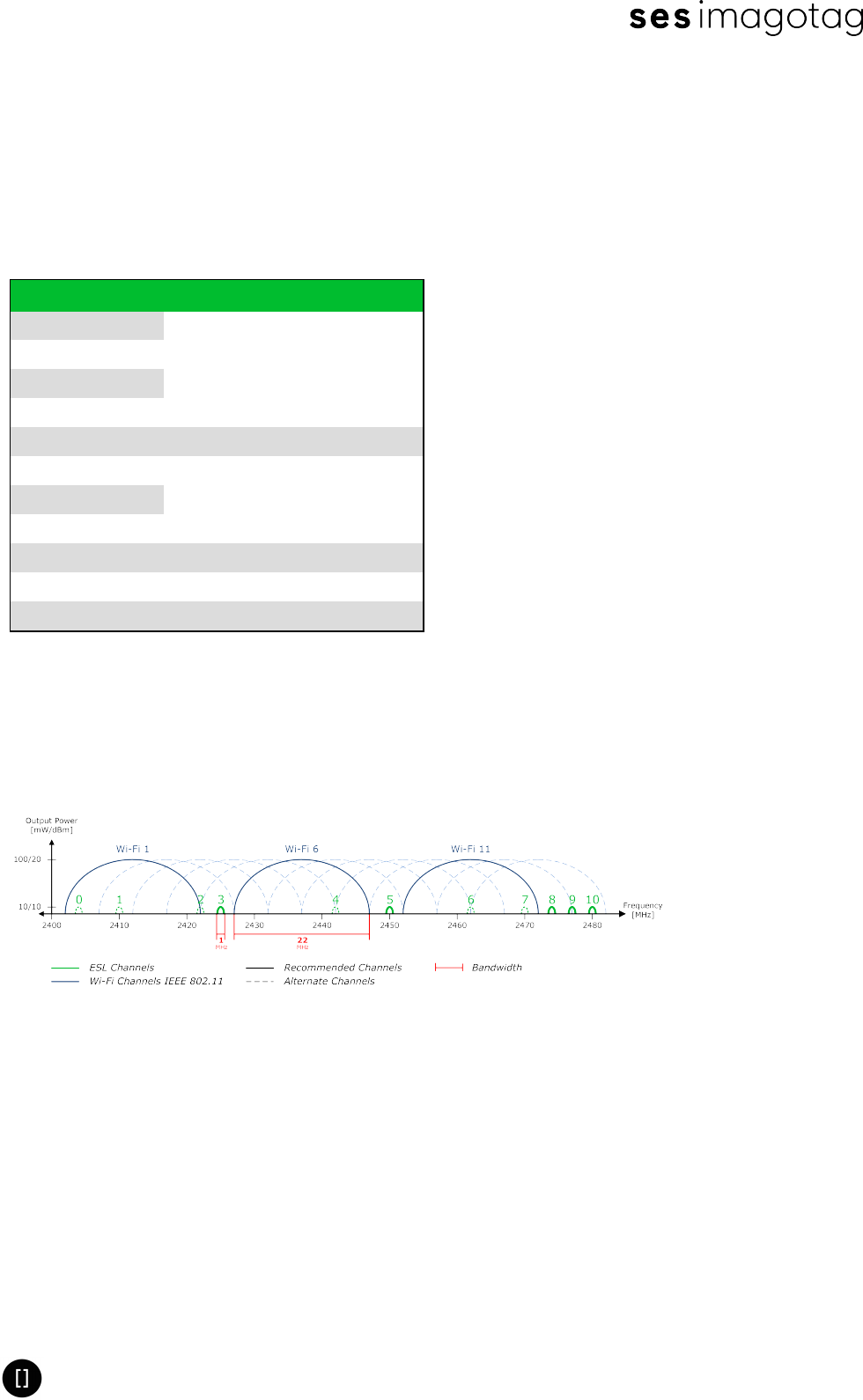
5.1 Used Channels
Although WIFI and ESL use the same frequency band (2.4 Ghz ISM Band), there are channels
that do not overlap (not interfering - recommended channels).
Kanal Frequenz WLAN Kanal (802.11b/g)
0 2404 MHz
WLAN 1 (2402 – 2422 MHz)1 2010 MHz
2 2422 MHz
3 2425 MHz not interfering
4 2442 MHz WLAN 6 (2427 – 2447 MHz)
5 2445 MHz not interfering
6 2462 MHz WLAN 11 (2452 – 2472 MHz)
7 2470 MHz
8 2474 MHz not interfering
9 2477 MHz not interfering
10 2480 MHz not interfering
FIGURE 1-10: Overview of used channels of the imagotag AP-2010
5.2 Difference WiFi and ESL protocol
In contrast to the proprietary developed time based imagotag ESL protocol the WiFi protocol
applies to the IEEE 802.11 standard.
FIGURE 1-11: WiFi and ESL frequencies and channels (22 Mhz bandwidth)
5.3 Cabel Specifications
You can use a commercially available LAN cable (CAT-5 or higher) for data connection and the
power supply (if PoE is used) of the imagotag AP-2010.
Product Specification AP-2010
Page 16 of 27
5.4 Power Supply Specifications
Sunny Computer Technology Europe s.r.o.
lModel: SYS1541-1505-Wxx
lInput: 100-240 V ~ 1.0 A MAX, 50-60Hz
lOutput: 5V 3A
lOutput Power: 15W MAX
lOperating Temperature: 0° C to + 40° C
lMTBF: 50.000 hours full rated load operation at 40 ℃, according to the MIL-HDBK-217F
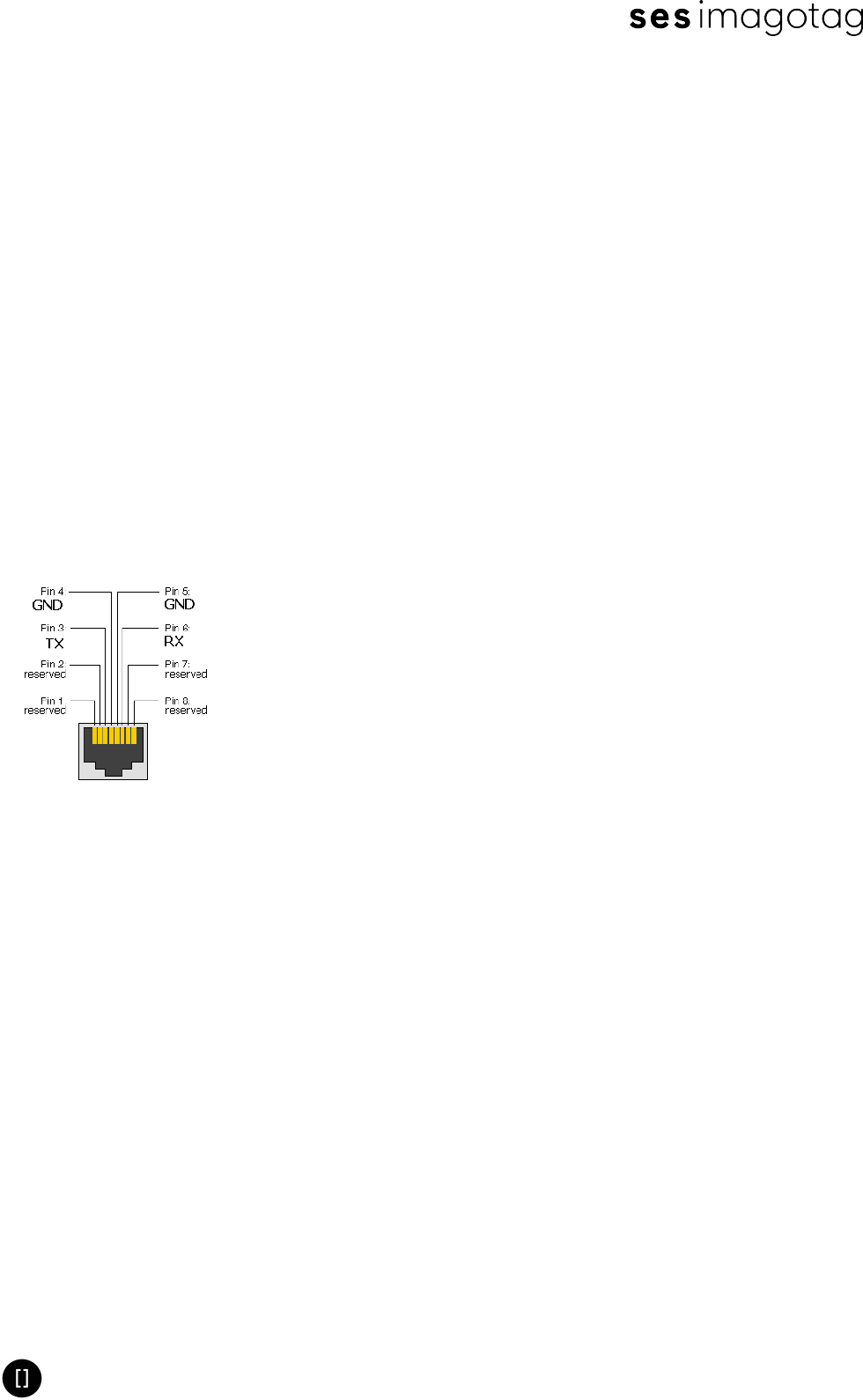
5.5 Pinout RJ45 Ethernet
lPin 3 – TX (AP to PC)
lPin 6 – RX (PC to AP)
lPin 4/5 – Ground
5.5.1 Pinout

Product Specification AP-2010
Page 17 of 27
6 Electrical & RF Characteristics
6.1 General Technical characteristics
Power:
lExternal Power Supply: 5 VDC / 3A
lPower Supply via PoE: IEEE 802.3af, IEEE 802.3at
lPower consumption: 15W MAX, typical 3W
Technology:
lRadio technology: proprietary
lOperating frequency: 2.4 GHz (ISM-Band) – 2.4835 GHz
lTransmitted power: ≤ 10 dBm
lNumber of Channels: 11
lAccess protocol: proprietary
Other:
lMTBF: >300.000h at 40°C according to SN29500
6.2 Power and Current Consumption
Power consumption measurements indicate that the AP-2010 has the following patterns:
lOperating Current: ≤ 60 mA (max. current)
lOperating Power: ≤ 280 mW
lSupply Voltage: 5V ± 10%
6.3 General Specifications
6.3.1 Hardware
l600 MHz ARM Cortex-A8
lMemory - 512MB DDR2 memory
lSD/MMC card connector
o512 MB card with imagotag software preinstalled
lPower over Ethernet (PoE IEEE 802.3af / IEEE 802.3at)
oThe original IEEE 802.3af-2003 PoE standard provides up to 15.4 W of DC power
(minimum 44 V DC and 350 mA to each device). Only 12.95 W is assured to be avail-
able at the powered device as some power is dissipated in the cable.
lOther Interfaces
oSerial RS232 Interface
o10/100 Ethernet Interface
lPower
oPower source options (DC, PoE)
o3.3 V I/O operation
oDC supply 5V ± 10%, 3A Max

Product Specification AP-2010
Page 18 of 27
6.3.2 Software Package
lOS: Embedded Linux
lAP-2010 application software
lRF Firmware

Product Specification AP-2010
Page 19 of 27
7 Environmental
7.1 Humidity and Operating Conditions
lTemperature: 0° C to + 40° C
lHumidity: 10% to 80% (non-condensing)
7.2 Storage Conditions
lTemperature: -20 °C to + 70 °C
lHumidity: 10% to 85% (non-condensing)
7.3 Cleaning Instructions
Steps:
1. Shutdown Access Point
2. Plug Out Power Supply (AC or PoE)
3. Clean the Access Point with the help of a damp cloth
Note: Do not use liquid or aerosol cleaners.
Product Specification AP-2010
Page 20 of 27
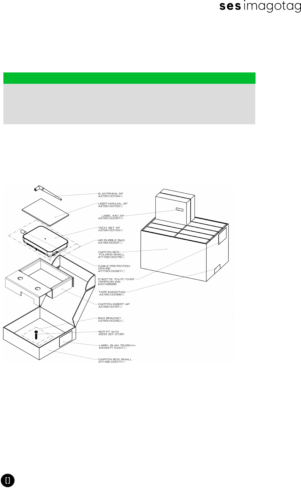
8 Packing
8.1 Packing Dimensions
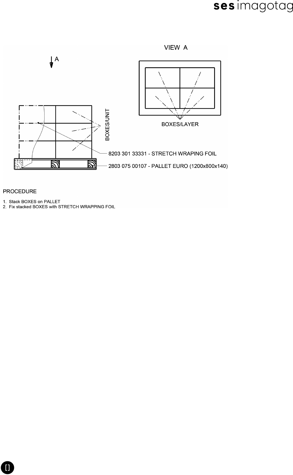
DIMENSIONS STACKING QUANTITY
LENGTH WIDTH HEIGHT
BOX 520 350 260 LAYER / UNIT 3 SETS / BOX 10
PALLET 1200 800 140 BOXES / LAYER 4 SETS / LAYER 40
UNIT 1200 800 960 BOXES / UNIT 12 SETS / UNIT 120
Imagotag AP-2010 / Box: 10
8.2 Illustrations
Product Specification AP-2010
Page 21 of 27
8.3 Palletization

Product Specification AP-2010
Page 22 of 27
9 Certifications
9.1 Types
Housing, board and the display are conform with the ROHS Directive
The product meets the EU safety, health and environmental protection
requirements and has the approval of CE marking
This device complies with part 15 of the FCC Rules.
9.2 Overview
Caption RoHS Food
Contact CE FCC/IC
AP-2010 • •2•5
1FCC/IC certified since calendar week 9 / year 2015 (the FCClogo must be printed on the nameplate)
2R&TTE EN 300328 V1.8.1
3R&TTE EN 300328 V1.9.1
5There are two different versions of the AP available. One CE and one FCC version.
9.3 Applied Standards
Information Technology Equipment
EN 60950-1/A2:2013
UL 60950-1/A2:2014
CSA CAN/CSA-C22.2 NO.60950-1-07
EMV
EN 301489-17 V2.2.1
R&TTE
EN 300328 V1.8.1 / EN 300328 V1.9.1
Human Exposure to Electromagnetic Fields
EN 62479:2010
Radio international
FCC:47 CFR Part 15 (USA)
RSS-210 Issue 8 (Canada)
9.4 Declaration
The company imagotag GmbH declares on his own responsibility that the AP-2010 corresponds
to the standards mentioned above.
9.4.1 FCC
This device complies with part 15 of the FCC Rules. Operation is subject to the following two
conditions: (1) This device may not cause harmful interference, and (2) this device must accept

Product Specification AP-2010
Page 23 of 27
any interference received, including interference that may cause undesired operation.
Changes or modifications not expressly approved by the party responsible for compliance could
void the authority to operate the equipment.
9.4.2 IC
This device complies with Industry Canada licence-exempt RSS standard(s). Operation is
subject to the following two conditions: (1) this device may not cause interference, and (2) this
device must accept any interference, including interference that may cause undesired
operation of the device.
Le présent appareil est conforme aux CNR d'Industrie Canada applicables aux appareils radio
exempts de licence. L'exploitation est autorisée aux deux conditions suivantes : (1) l'appareil
ne doit pas produire de brouillage, et (2) l'appareil doit accepter tout brouillage radioélectrique
subi, même si le brouillage est susceptible d'en compromettre le fonctionnement.
9.4.3 NCC 警語:
經型式認證合格之低功率射頻電機,非經許可,公司、商號或使用者均不得擅自變更頻率、
加大功率或變更原設計之特性及功能。
低功率射頻電機之使用不得影響飛航安全及干擾合法通信;經發現有干擾現象時,應立即停
用,並改善至無干擾時方得繼續使用。
前項合法通信,指依電信法規定作業之無線電通信。低功率射頻電機須忍受合法通信或工
業、科學及醫療用電波輻射性電機設備之干擾。

Product Specification AP-2010
Page 24 of 27
10 Problems which requiring maintenance or replacement of
the AP-2010
Plug out the power supply and contact the imagotag GmbH when it comes to the following
cases:
lThe AP-2010 was strewn with liquid.
lThe AP-2010 has been dropped or damaged.
lThe LAN port of the AP-2010 is damaged.
lThe antenna connection thread is damaged.
lThe LED of the AP-2010 no longer lights up.
Contact the manufacturer if despite intended purpose the device is not working and none of the
mentioned cases occurred.

Product Specification AP-2010
Page 25 of 27
11 Intended Use
The imagotag AP 2010 is exclusively designed to connect to electronic labels of the company
imagotag GmbH via radio.
The device may only be used in areas where the environmental conditions be the same as
descripted in the chapter (see Environmental on page 19).
Intended use includes the observance of all information in this system manual.
Product Specification AP-2010
Page 26 of 27
12 Improper Use
Any use that is not mentioned in Section Intended Use, shall be deemed to be improper. Any
damage which result from improper use, the operator will assumes liability.
The following usage is not allowed:
lNever dismantle the electronic device because except battery there is no com-
ponent which could be changed by someone who is not qualified.
lDon't drop it.
lKeep it away from water.
lStrictly avoid direct contact with groceries.
lDon’t use the electronic device with defective parts.
lDon’t use the electronic device with spare parts and accessories which are
not examined and approved by the imagotag GmbH.
lUnauthorized changes or modifications to the electronic device and their com-
ponents without the consent of imagotag GmbH are not allowed.
lDon't heat, recharge or bend battery.
lWe take no responsibility for stolen ESLs without encryption.
lKeep away batteries from children.
lDon't throw defective batteries into the dustbin. Give them to a reprocessing
company.
lDon't throw electronic device into the dustbin. Give them to a reprocessing
company.
lContact imagotag GmbH for more details about this process.

Product Specification AP-2010
Page 27 of 27
13 Warranty
The device is provided with a warranty seal. Is this warranty seal destroyed, expire at the same
time, all warranty claims.