SES imagotag E00019 digital network transceiver User Manual My
SES-imagotag GmbH digital network transceiver My
UserManual.wiki
>
SES imagotag
>
E00019 User Manual
>
Quick start guide
Contents
1.
Quick start guide
2.
Compliance statements
Quick start guide
Navigation menu
Upload a User Manual
Namespaces
Wiki Guide
HTML
PDF
Info
Views
User Manual
Discussion / Help
Navigation

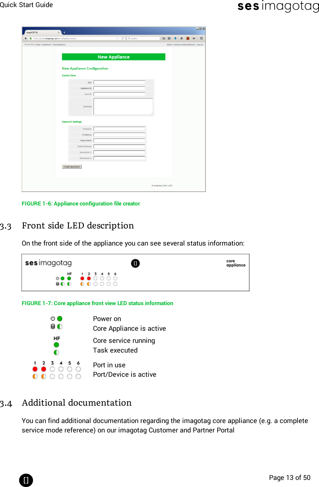
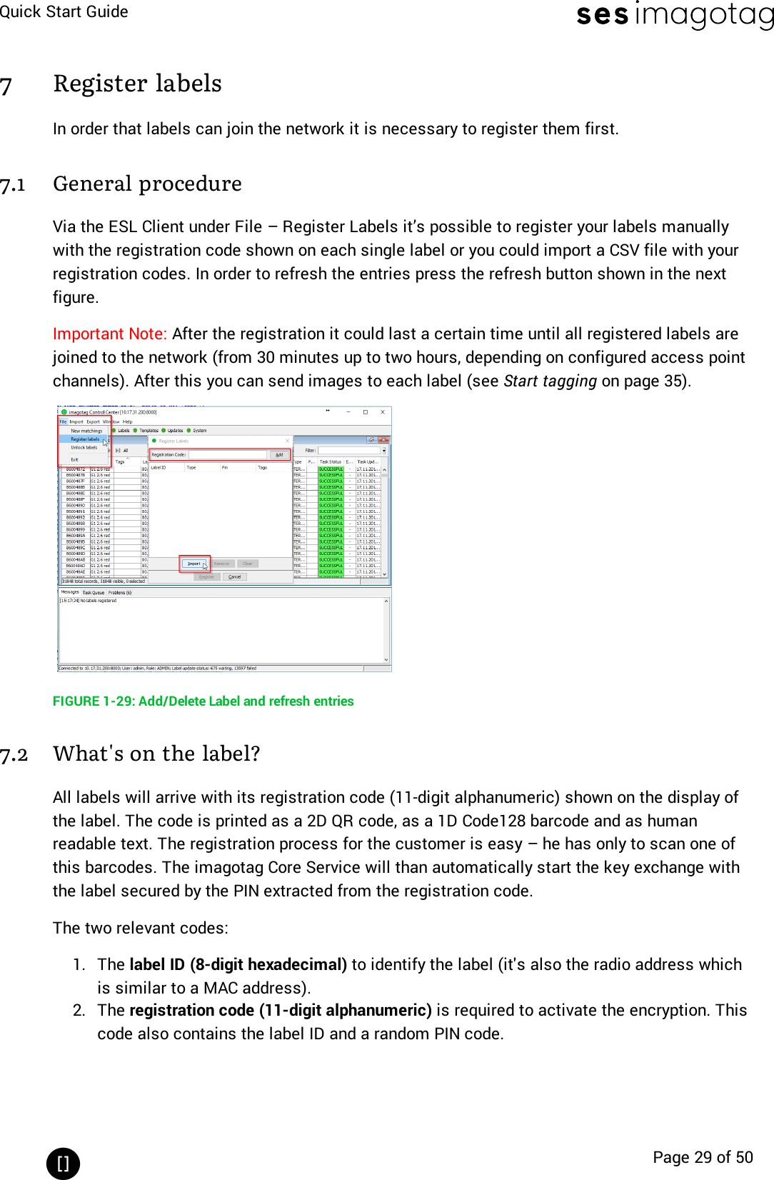
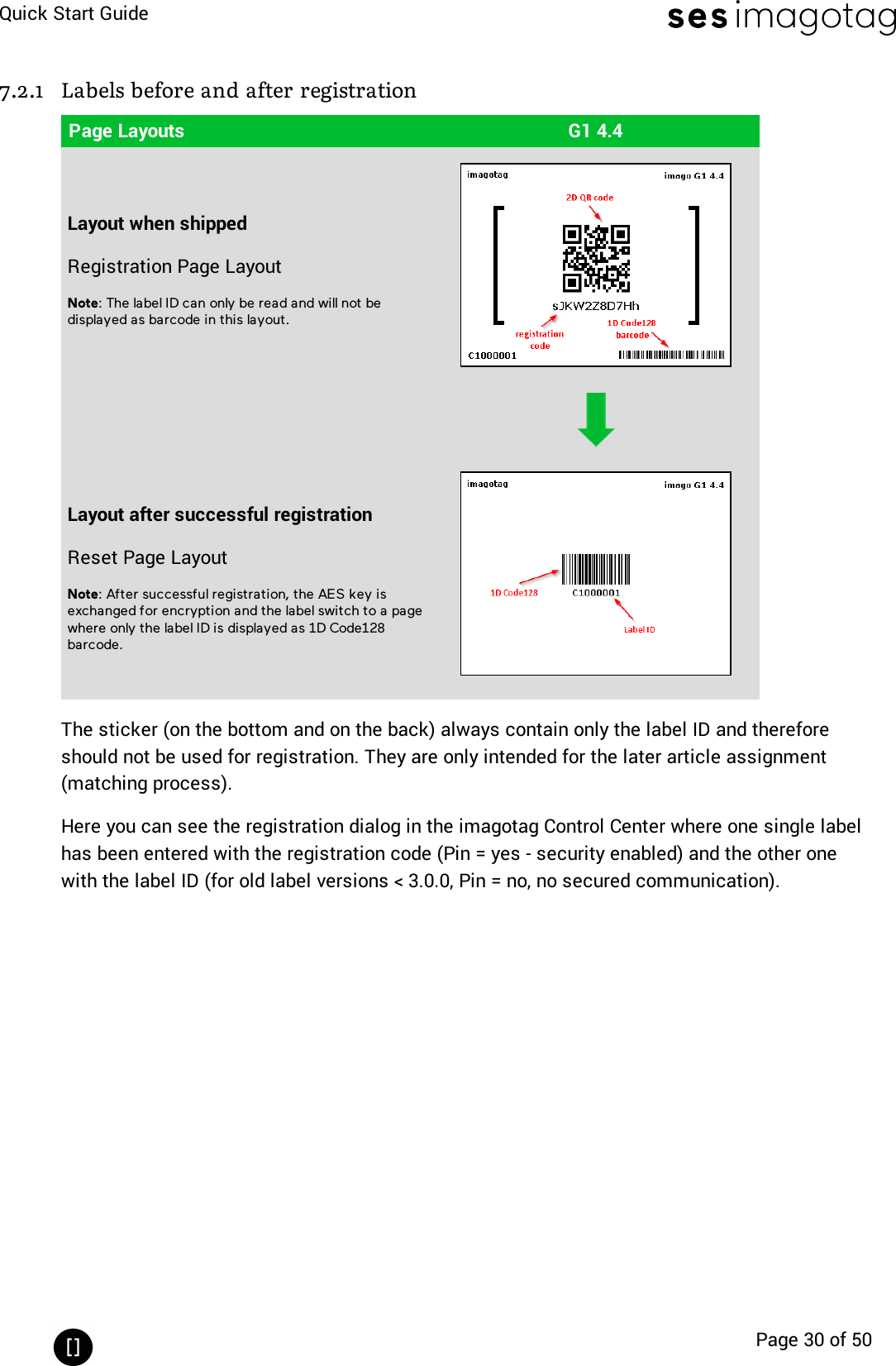
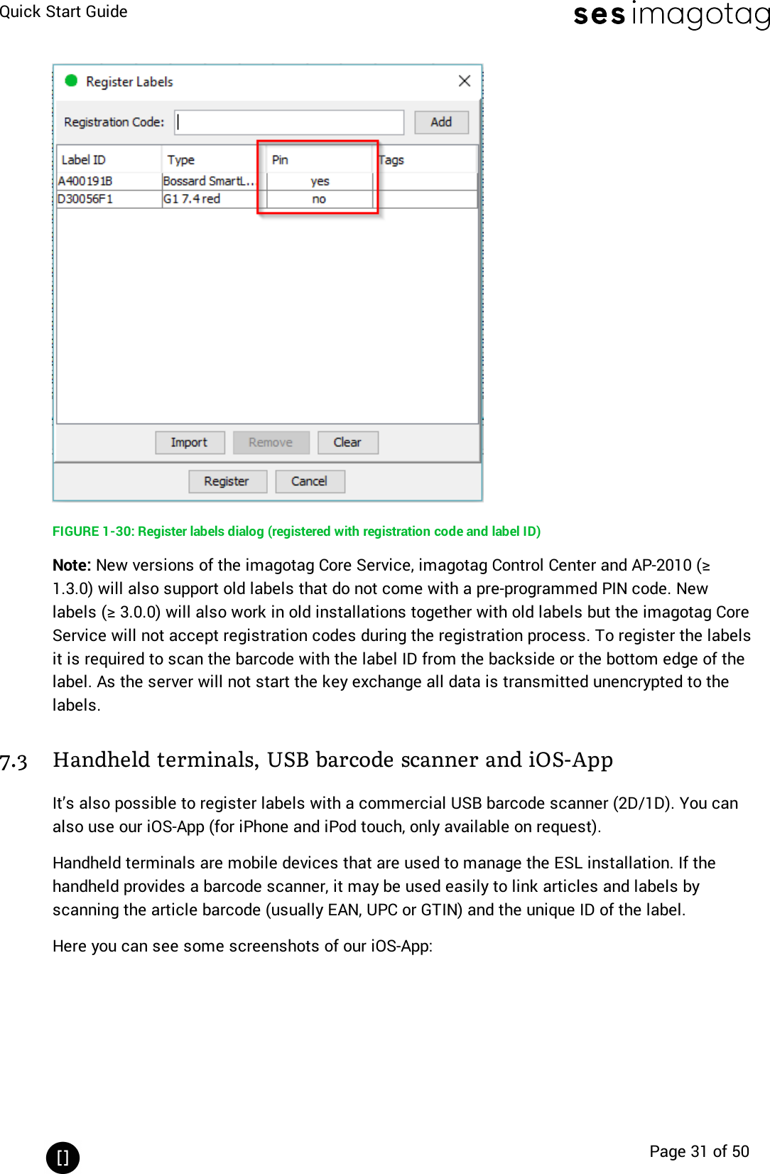
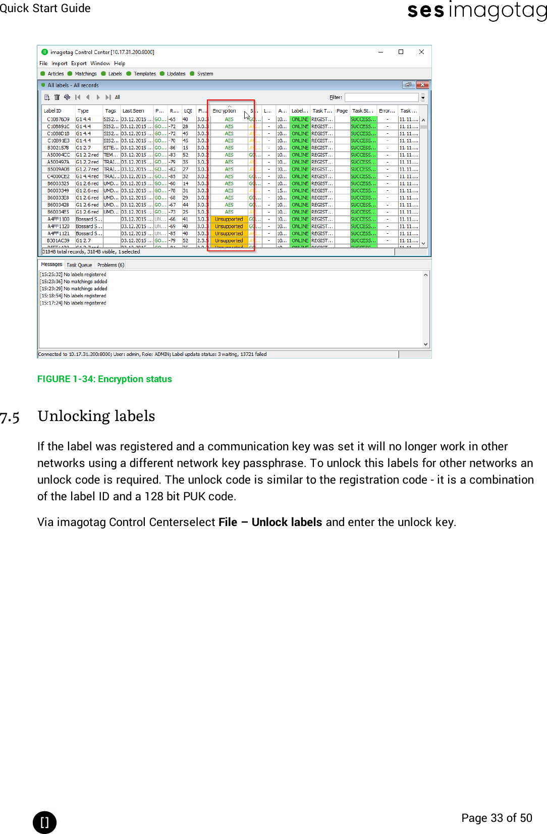
![Quick Start GuidePage 2 of 50[Introduction] 41 Electronic Shelf Labeling – A brief introduction 42 What’s in your Smart Box? 53 The G1 label family 63.1 Key Features 74 Core appliance 84.1 Key Features 8[Getting Started] 91 Get the latest software and documentation 92 Install software 92.1 System requirements 92.2 Installation process 92.3 imagotag Customer and Partner Portal 103 Core appliance initial setup 113.1 USB device configuration 113.2 Configuration file creator 123.3 Front side LEDdescription 133.4 Additional documentation 134 Start Core Service and Control Center 144.1 Starting imagotag Core Service 144.2 Starting imagotag Control Center 154.3 Activating your license 175 Access Point Configuration 195.1 Connect and configure AP-2010 195.2 Connect and configure MAP-2014 T/Q & LANCOM L-151e/322e 225.3 Selecting channels 276 Setup Security 286.1 General encryption features and how does it work 286.2 Set the encryption key 287 Register labels 297.1 General procedure 297.2 What's on the label? 29](https://usermanual.wiki/SES-imagotag/E00019.Quick-start-guide/User-Guide-3653177-Page-2.png)
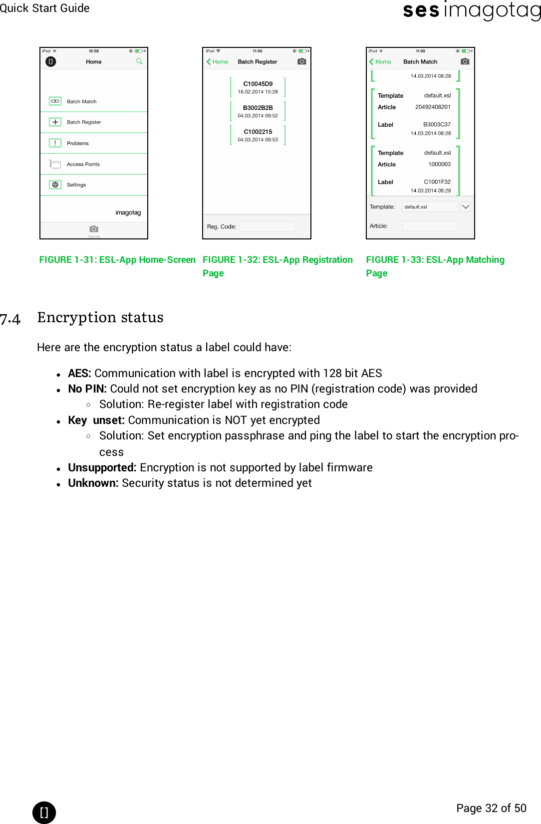
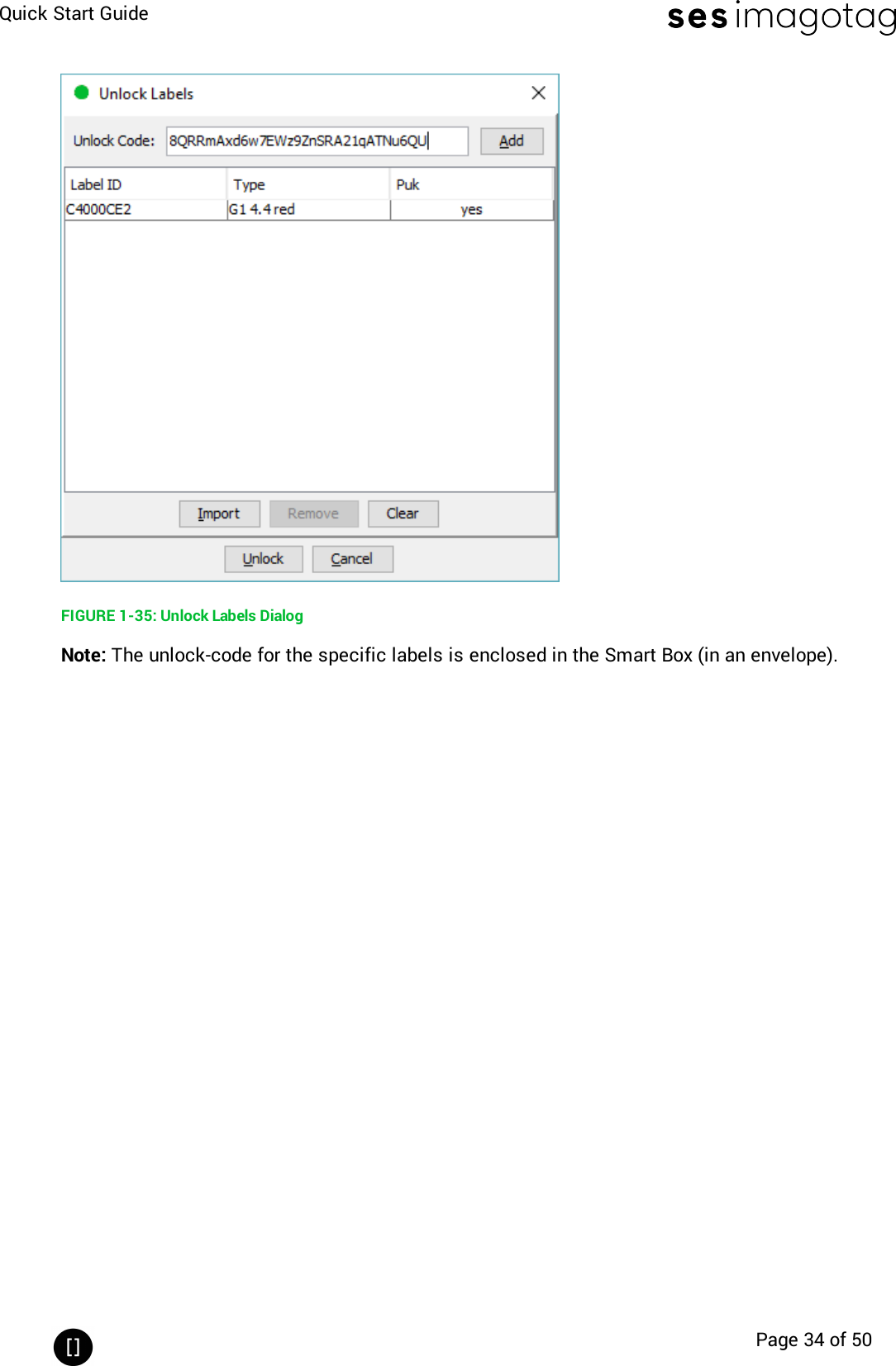
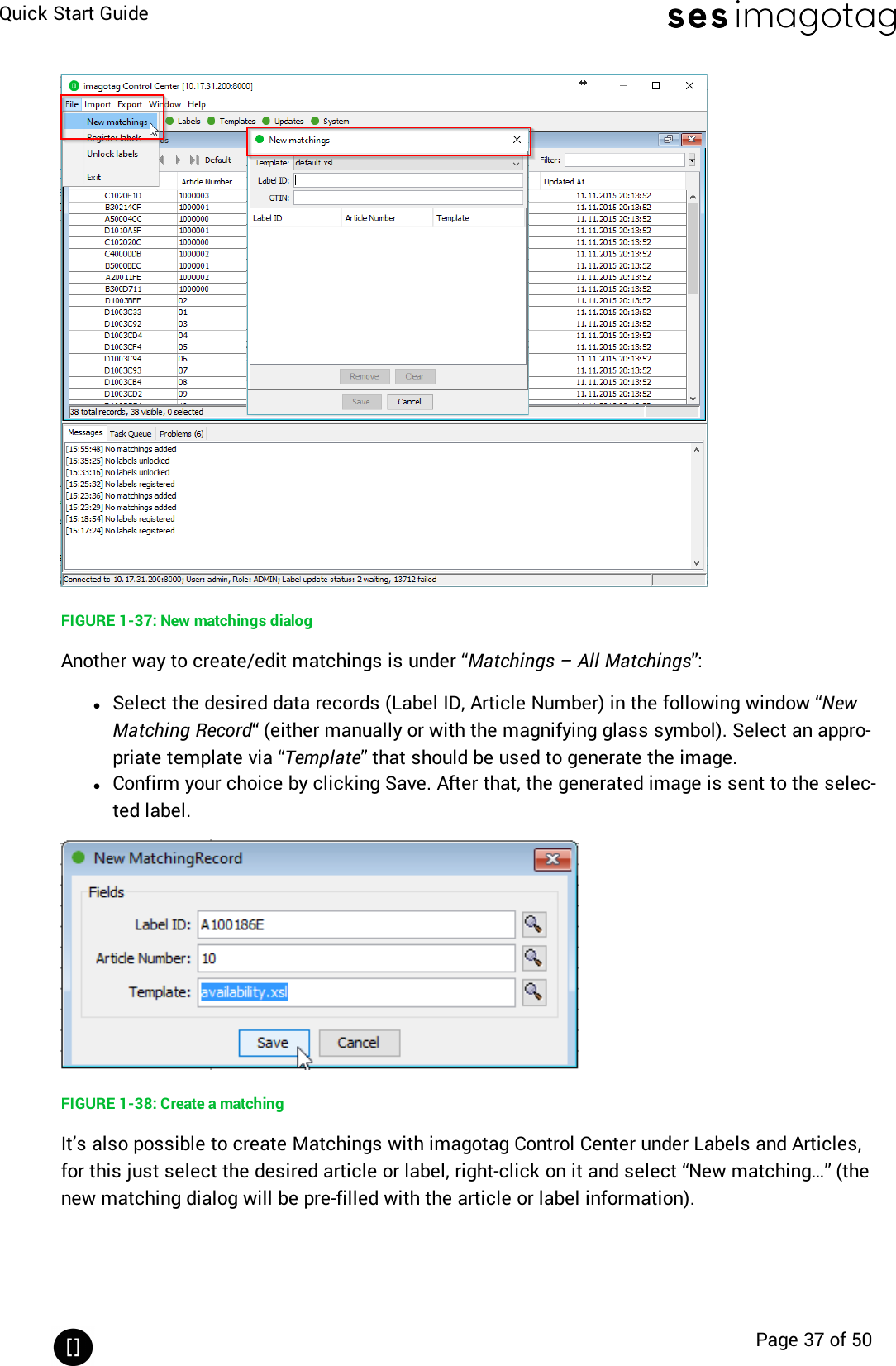
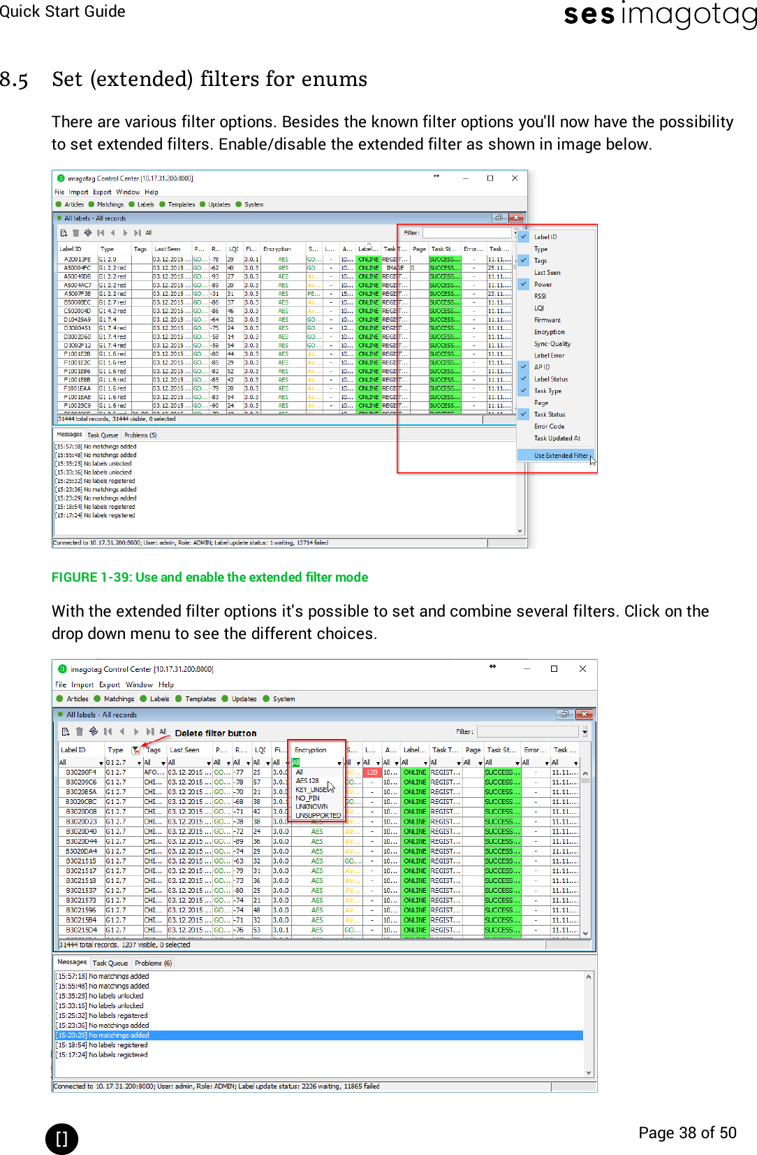
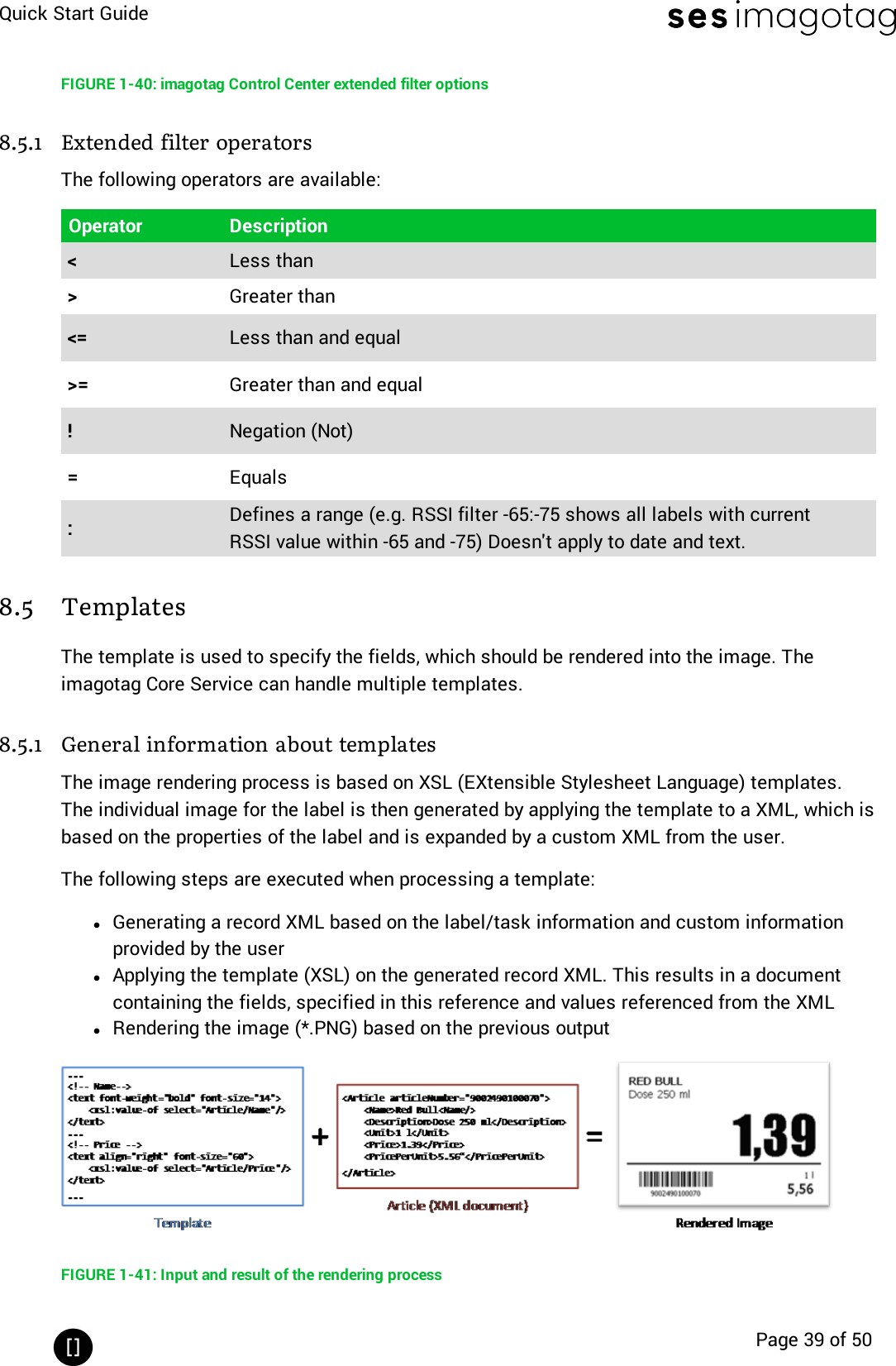
![Quick Start GuidePage 3 of 507.3 Handheld terminals, USB barcode scanner and iOS-App 317.4 Encryption status 327.5 Unlocking labels 338 Start tagging 358.1 What can I do now? 358.2 Sending pictures to labels 358.3 Article management 358.4 Matchings/Multi-Facing 368.5 Set (extended) filters for enums 388.5 Templates 399 Integration 449.1 Webservice integration 449.2 Plugins 449.3 Custom integration 44[Troubleshooting] 451 FAQ 451.1 imagotag Core Service Dashboard 471.2 Running the imagotag Core Service as a background service 471.3 Where can I find the license file for my SmartBox? 481.4 Deleting the demo articles 481.5 Labels don’t come online 481.6 The encryption does not work 481.7 Unlocking labels 481.8 Starting Java applications 481.9 Encoding problems 501.10 Further documentation 50](https://usermanual.wiki/SES-imagotag/E00019.Quick-start-guide/User-Guide-3653177-Page-3.png)
![Quick Start GuidePage 4 of 50[Introduction]1 Electronic Shelf Labeling – A brief introductionAn electronic shelf label is a device that shows article data and price information on itsdisplay. In comparison to printed labels the information is automatically updated if price orarticle data changes.FIGURE 1-1: Electronic Shelf LabelinglCost reduction through eliminationof manual price changeslFully automatic price updates fromthe headquarters to the branchstores within secondslProcess security and price integrity– 100% correlation between cashpoint and shelflIncreased flexibility in price designand immediate reaction to marketsituation Image gain due to use ofhighly modern technologylSimplified processes for store per-sonnellEnhanced sales & price profitabilitymaximize price performance andprofit opportunities](https://usermanual.wiki/SES-imagotag/E00019.Quick-start-guide/User-Guide-3653177-Page-4.png)
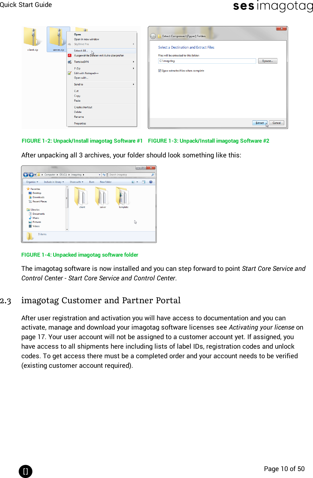
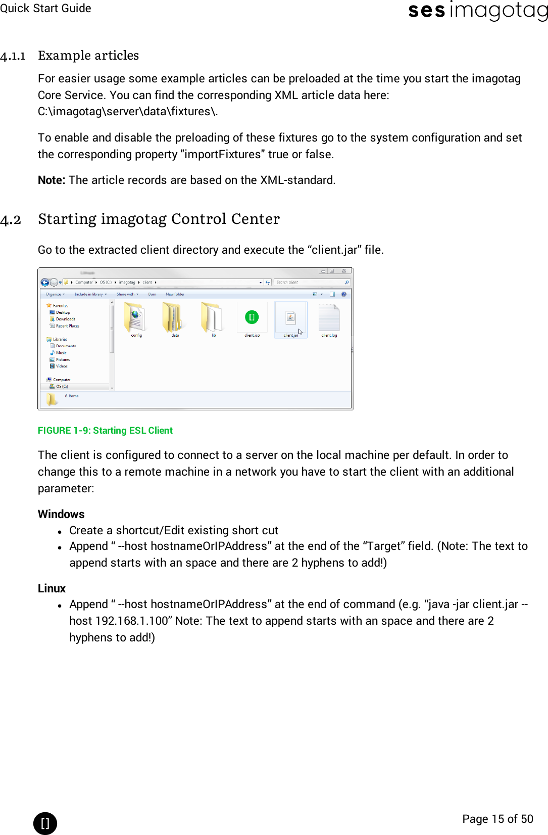
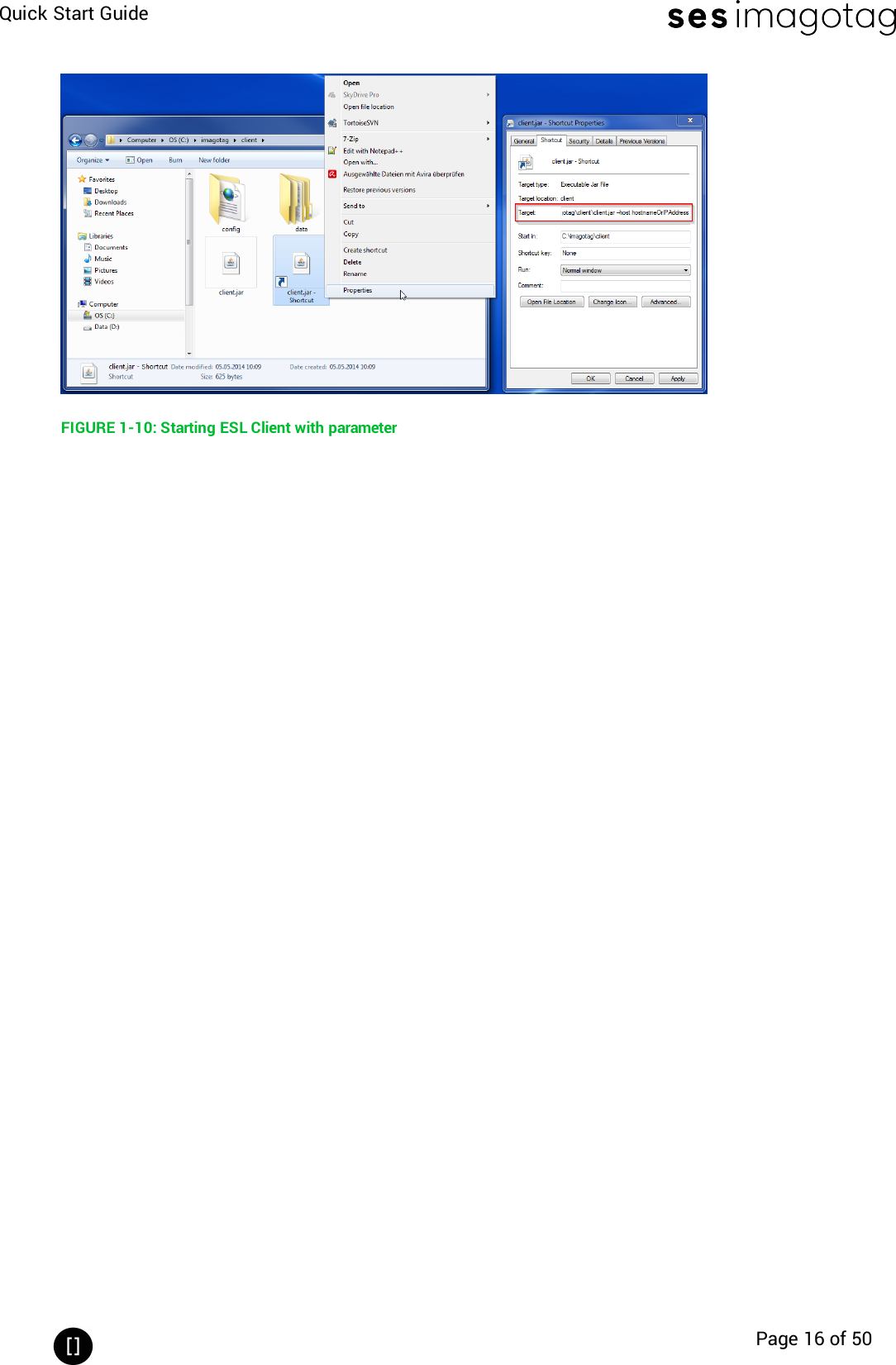
![Quick Start GuidePage 9 of 50[Getting Started]1 Get the latest software and documentationRegister at the imagotag Customer and Partner Portal to get access to the latest softwaresuite and documentation.https://portal.imagotag.comAfter registration your access is limited. Contact the imagotag Support Team(support@imagotag.com)to get further access and information.2 Install softwareThere’s several software you’ll have to install in order to configure and setup your ESL system.You’ll just have to extract the following 3 archives in a location of your choice:1. imagotag Core Service (previously known as imagotag ESL Server) <server.zip>2. imagotag Control Center (previously known as imagotag ESL Client)<client.zip>3. Template Editor <template.zip>2.1 System requirementslServer hardware: Pentium 4 (2 GHz or higher), 2 GB RAMlJava Runtime Environment Version 6, Update 36 or higherlWindows XP, Windows 7, Windows Server 2008 (R2), Windows 10, Suse Enterprise Linux11, Ubuntu 12 (all 32/64-bit versions), Mac OS Xlimagotag Core Software Suitelimagotag AP-2010limagotag LabelslLicense key2.2 Installation processPlease unpack the zip-archives <server.zip>, <client.zip> and <template.zip> on your machine -e.g. under C:\imagotag\.Note: To unpack the zip-files you can either use the windows internal archive-unpacker (seescreenshots) or an unpack tool of your choice (e.g. the free tool 7zip – www.7zip.org).](https://usermanual.wiki/SES-imagotag/E00019.Quick-start-guide/User-Guide-3653177-Page-9.png)
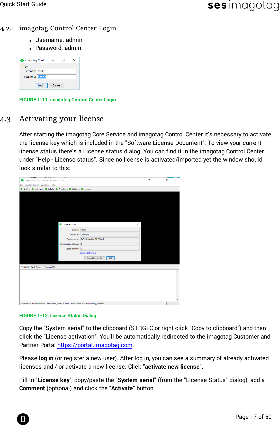
![Quick Start GuidePage 14 of 504 Start Core Service and Control Center4.1 Starting imagotag Core ServiceIf you've recently configured your imagotag core appliance the ESLService is already runningand you can step forward to the next step 15In order to start the ESL Service with the default configuration, just execute the jar file“server.jar” as described in [Troubleshooting] and wait for the small service GUI to show up (ifthe window doesn’t show up after all, make sure your Java installation and configuration iscorrect).FIGURE 1-8: Core Service web UIThe service will listen to TCP connections on Port 8000 and 8001 and UDPconnections on Port 8000. Please make sure that there is no firewall issueand/or interference with other systems.After start of the service you can check the web-GUI of the server:URL: http://<host|ip>:8000Login: admin/adminDuring the first start the imagotag Core Service will automatically create a Derby1database. Ifanother database connection is needed or preferred, the connection parameters should bevalidated by imagotag.Note: As you can see there are several level numbers, by default the server instance will startin level 3. You can find the description of the different levels in the Developer Reference (whichis also part of the documentation available at the imagotag Customer and Partner Portal) under“Integration Levels”.1Apache Derby, an Apache DB subproject, is an open source relational database implementedentirely in Java](https://usermanual.wiki/SES-imagotag/E00019.Quick-start-guide/User-Guide-3653177-Page-14.png)
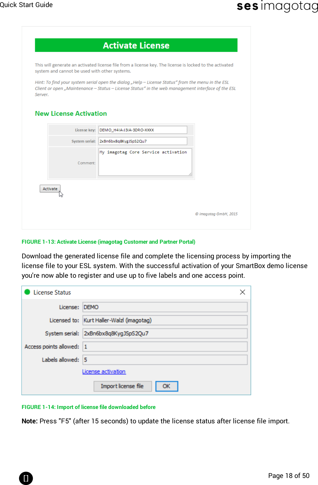
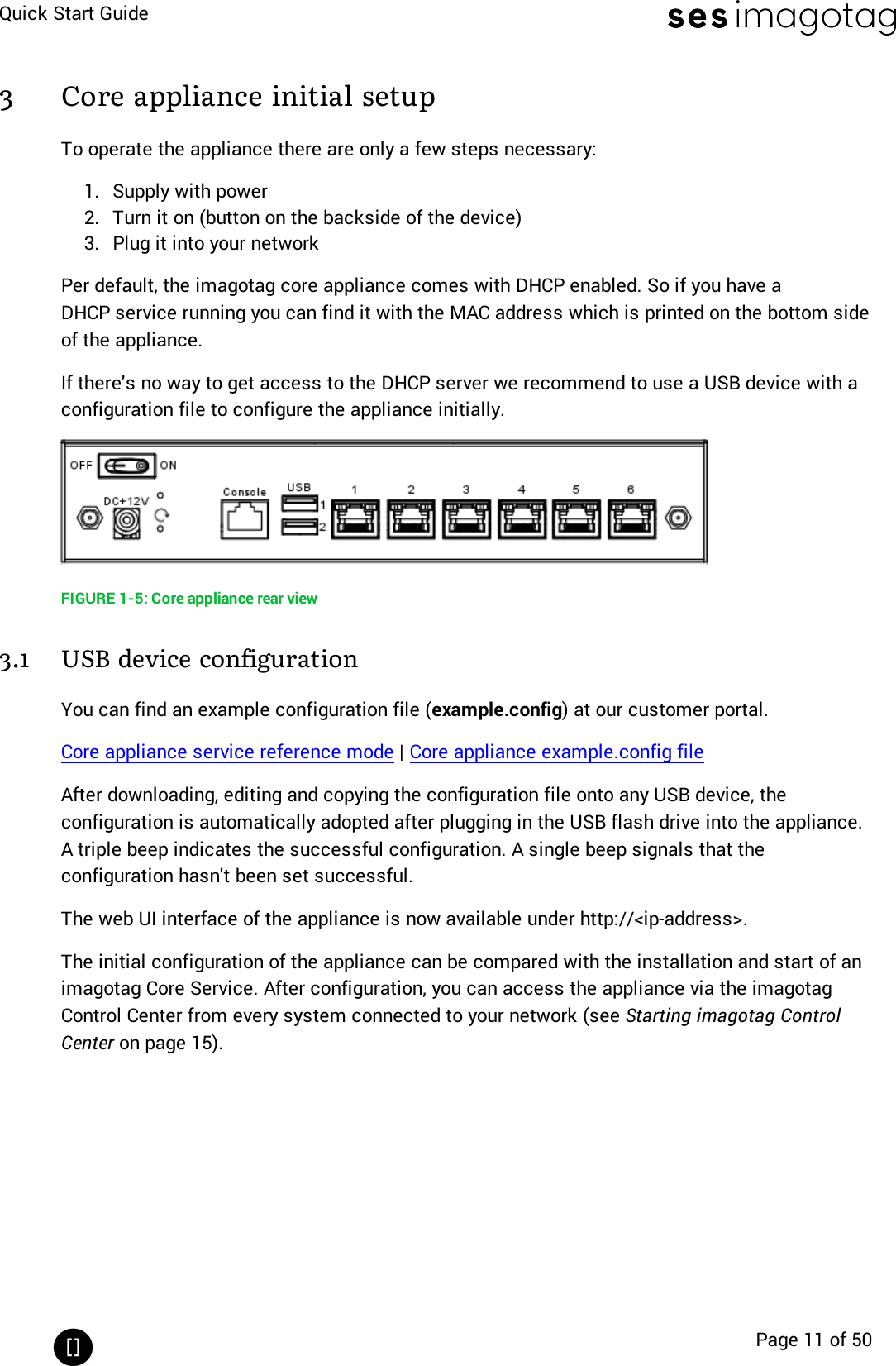
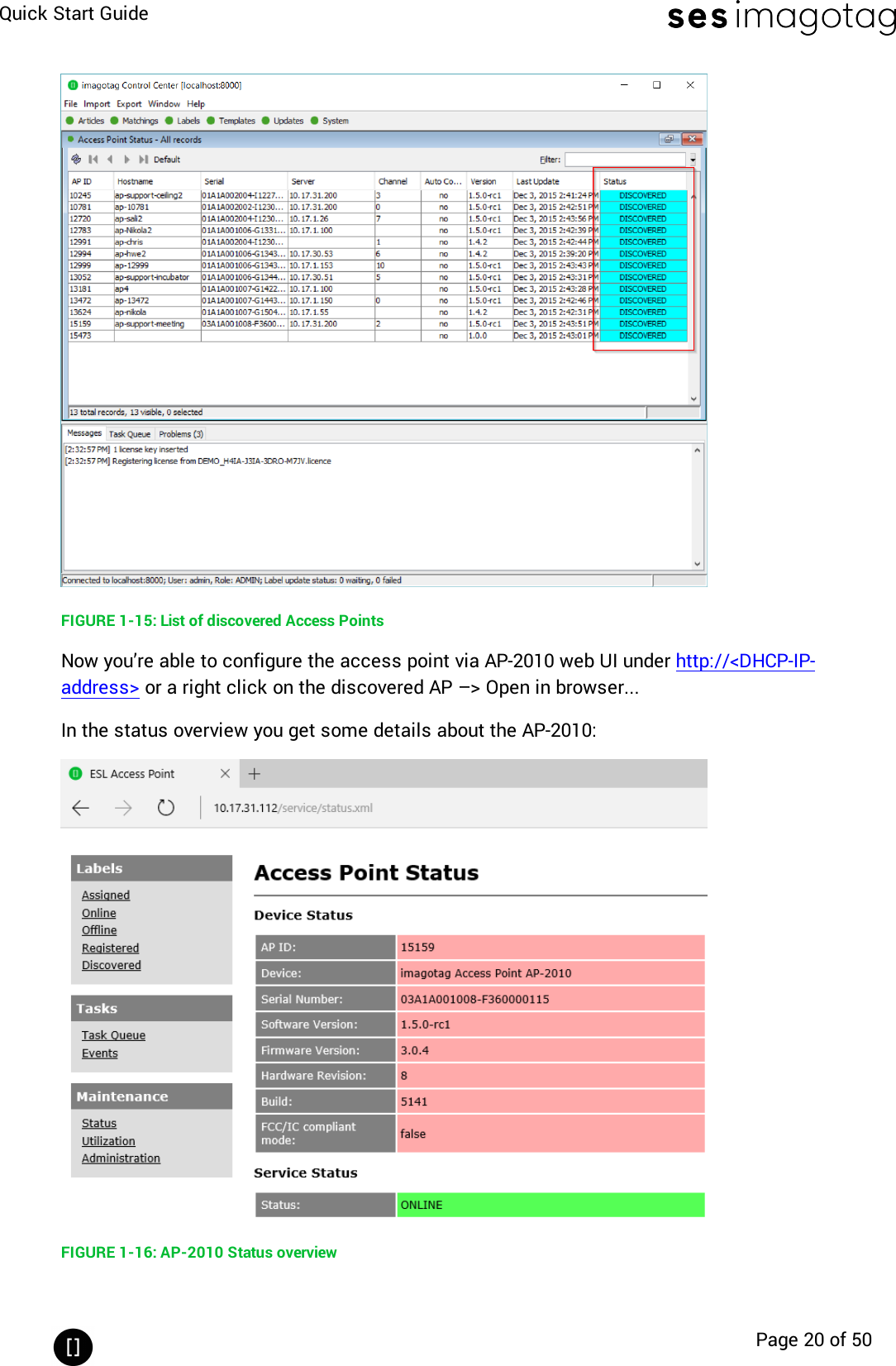
![Quick Start GuidePage 19 of 505 Access Point ConfigurationThe access points AP-2010, MAP-2014 T/Q and LANCOM L-131e/L-322e are the communicationcenter in the store that transmits information to the labels. In order to ensure thecommunication between imagotag Core Service, access point(s) and the labels the accesspoints have to be configured at the start of the imagotag Core Service.5.1 Connect and configure AP-20105.1.1 Connect and configureBefore labels are able to communication with the server at least one access point needs to beconfigured. In standard configuration the AP-2010 should get an IP-address via DHCP(recommended) and is accessible via imagotag AP-2010 web UI:URL: http://<host|ip>:8080Login: admin/adminImportant Note: In this part of the Quick Start Guide it is assumed that a DHCP server ispresent (you can find the steps to discover the access point without DHCP in theTroubleshooting section - see [Troubleshooting] on page 455.1.2 Discover the Access PointBefore you can configure the access point it’s necessary that the server will discover it.The following points have to be observed:lConnect your machine to the same network as the APlPlug in the power supply of the access pointlDuring the boot process of the access point, start the imagotag Core Service software onthe computerlWhen the access point is up (LEDturns orange), the server will discovery it with an IPaddress (Note: The discovering process may take up to 2 minutes)lUse the imagotag Control Center to connect to your imagotag Core ServicelUnder System – Access Point Status – the AP should be listed as discovered (after suc-cessful boot sequence)](https://usermanual.wiki/SES-imagotag/E00019.Quick-start-guide/User-Guide-3653177-Page-19.png)
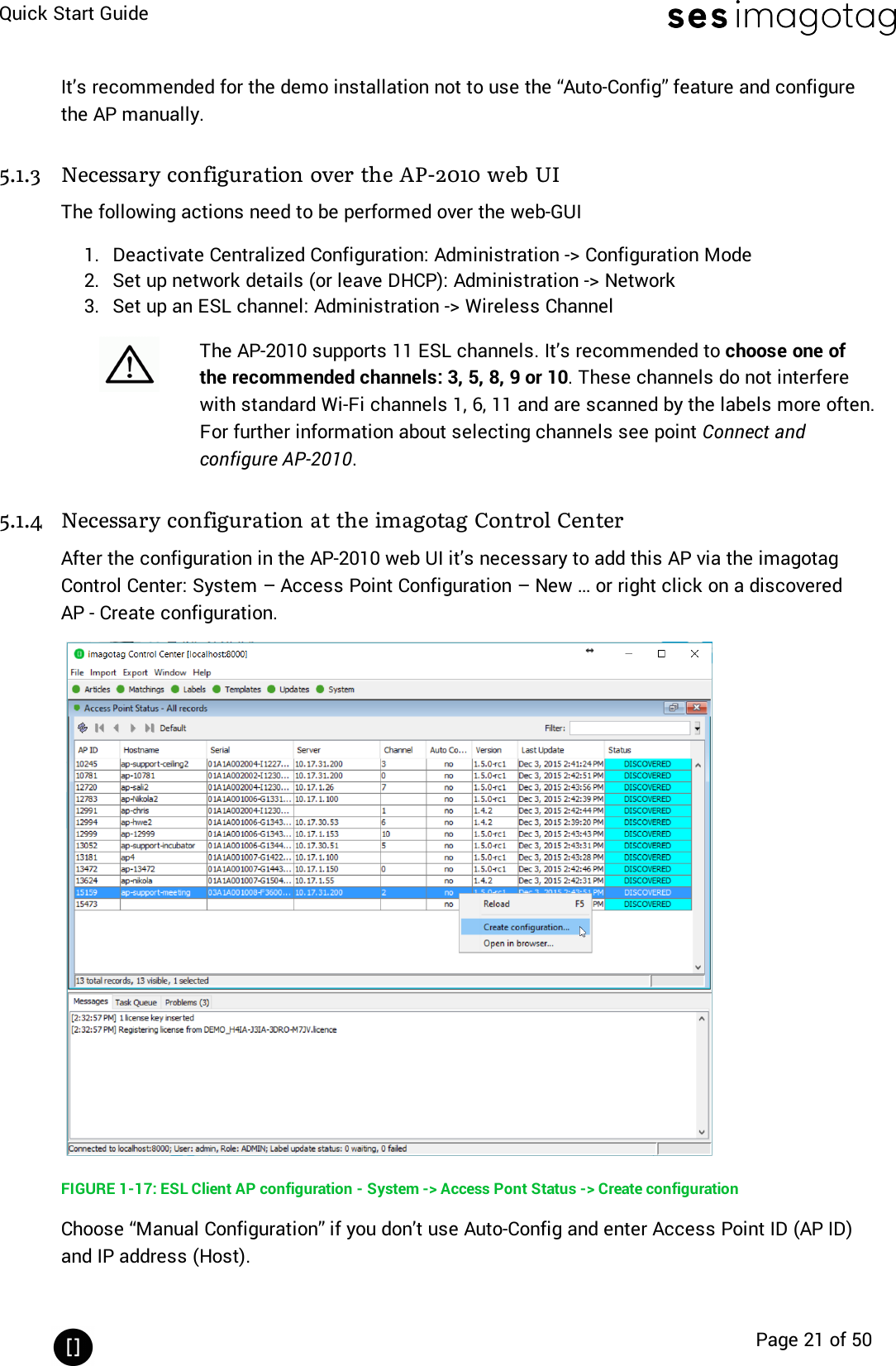
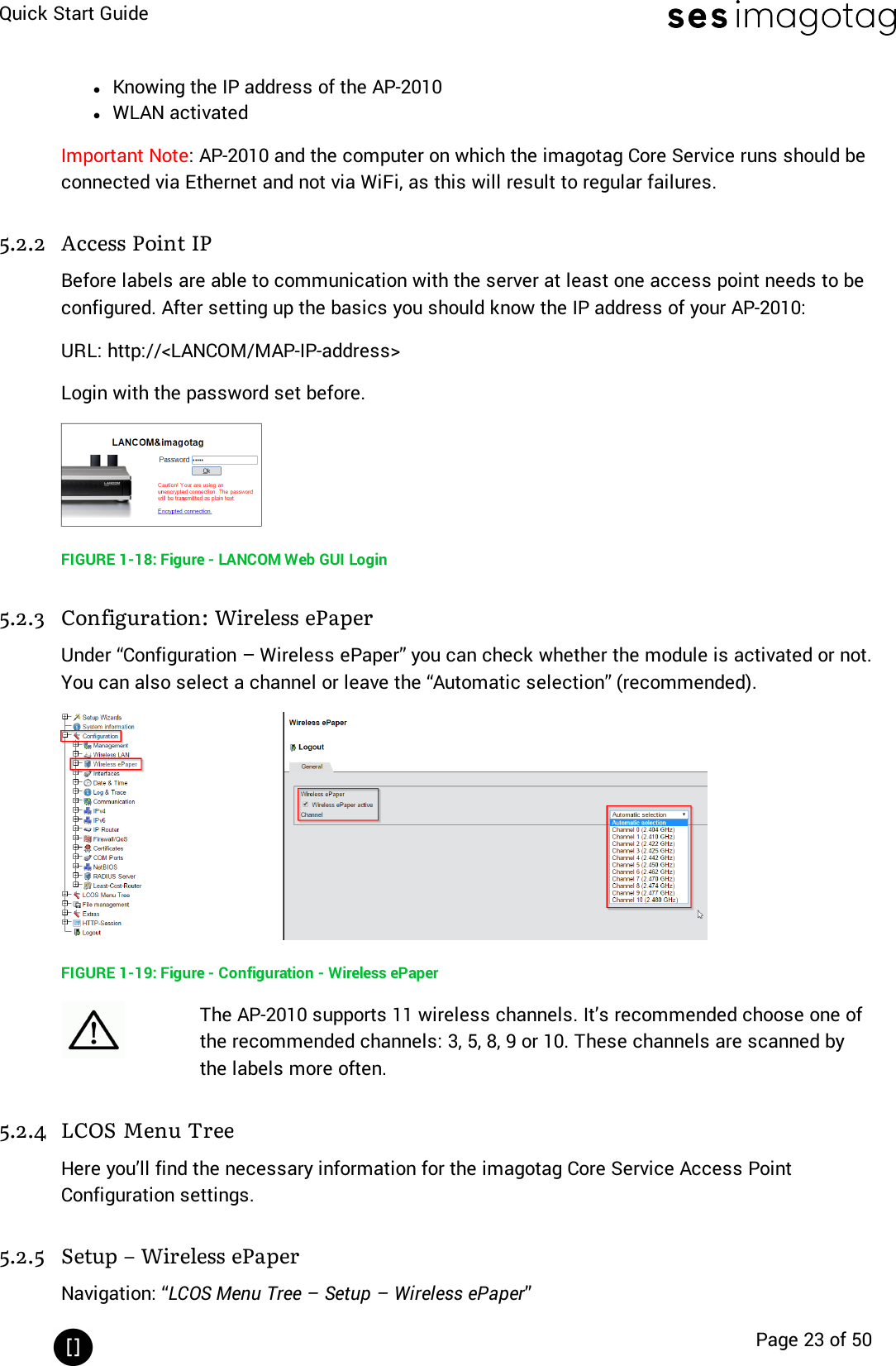
![Quick Start GuidePage 22 of 50Note: After the basic configuration in the AP-2010 web UI, it is also possible to fill in AP-ID andAP-IP-Address automatically. For this choose "Create Configuration..." under System – AccessPoint Status - Right click on the discovered and configured Access Point.After saving the AP configuration you should see the AP under System – Access Point Statusas ONLINE. In addition the AP status LED should turn BLUE.Note: It is possible to configure the access point via hostname. To get this working there hasto be a corresponding entry in the DNS.5.1.5 The Status LEDThere are several LED colors that indicates the main status of the access point.Color Description NoteRed Boot processCan take about 2 minutes, if it takes muchlonger, the device is defective and there is aneed for service.Blue Normal mode ---YellowOperational, but notconnected to any serveror no channel selected---Red (blinking) Running Firmware Update During this time there is no connection to theelectronic labelIf there are any problems regarding the access point please see chapter [Troubleshooting].5.2 Connect and configure MAP-2014 T/Q & LANCOM L-151e/322eThe LANCOM Access Point with Wireless-ePaper is the communication center in the store thattransmits price information to the labels. In order to ensure the communication between ESLserver, access point and the labels the LANCOM Access Point with Wireless-ePaper has to beconnected after the start of the ESL Server.One way to configure the access point is on the client.5.2.1 First configuration stepsAs described in the Installation Guide (printed version included in the package) you’ll have toconfigure the basic settings before setting up Wireless-ePaper using the imagotag imagotagCore Service.1. Installing the software or configuration using a web browser and setup wizards2. Deploying and connecting the device3. Searching for and configuring the deviceAfter setting up the basic settings the following points have to be fulfilled:](https://usermanual.wiki/SES-imagotag/E00019.Quick-start-guide/User-Guide-3653177-Page-22.png)
![Quick Start GuidePage 28 of 506 Setup SecurityThe security concept is based on individual registration codes for each label. Not only that thenew concept simplifies installations, it also provides stronger encryption and a secure keyexchange with individual communication key derived from a user defined network key.6.1 General encryption features and how does it worklSolid improved safetylEncrypted data type AES128 (Advanced Encryption Standard)lUser defined 128 bit network key for each installationlKey is distributed to labels automaticallyThe new system requires a user defined 128 bit network key for each installation. The key isderived from a passphrase that is defined by the customer and stored in the imagotag CoreService and used by all access points connected to that server to encrypt data communicationto the labels.A per-label communication key is transmitted to the labels during the registration of them.Each label is assigned an individual registration code (it combines label ID and PIN code andit’s an alphanumeric case-sensitive code with 11 characters). The imagotag Core Service willthan automatically start the key exchange with the label secured by the PIN extracted from theregistration code.6.2 Set the encryption keyFirst step is to set the parameter “encryptionPassphrase“ under System – Configuration (youcan choose the encryption Passphrase on your own).FIGURE 1-28: Set encryption keyNote: Do not change encryption passphrase if labels are already connected and encrypted (ifyou want to change the encryption passphrase you’ll first have to unlock all labels – see[Troubleshooting] on page 45).](https://usermanual.wiki/SES-imagotag/E00019.Quick-start-guide/User-Guide-3653177-Page-28.png)
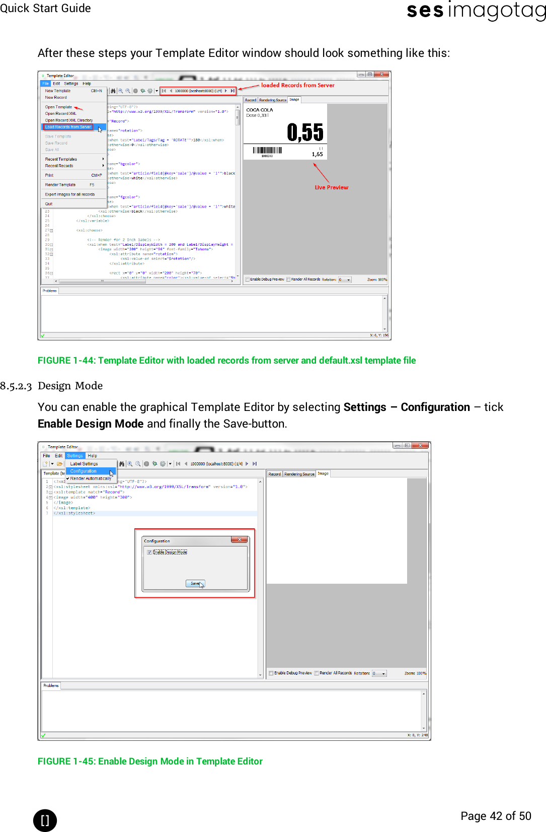
![Quick Start GuidePage 41 of 508.5.2.1 Starting Template EditorNavigate to the unpacked template directory (see point Installation process on how to unpackthe software package) and execute the “template.jar” file (see [Troubleshooting] on page 45).FIGURE 1-42: Starting the Template Editor8.5.2.2 Open default template-file and load records from server:lOpen the Template Editor by clicking the “template.jar” file located in the template-dir-ectory (In our example it should be C:\imagotag\teamplate\).lNext step is to create a new template file or to open an existing one (The default.xsl tem-plate file is located in the server-directory under C:\imagotag\server\data\template\).lTo get a live preview you’ll have to load some records, in our case we load the demo art-icle records from our running server, see the following figure.FIGURE 1-43: Load Records from Server](https://usermanual.wiki/SES-imagotag/E00019.Quick-start-guide/User-Guide-3653177-Page-41.png)
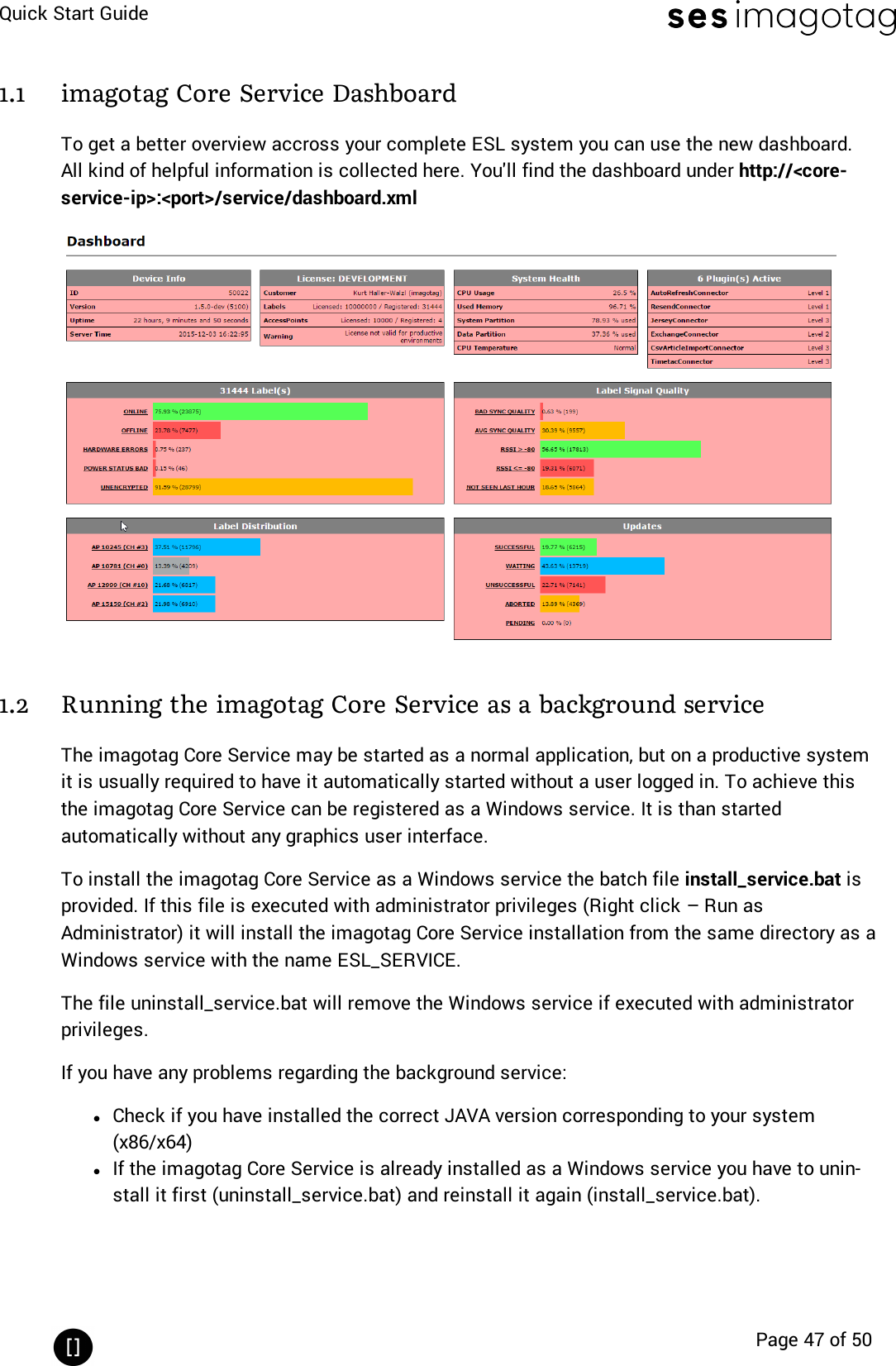
![Quick Start GuidePage 45 of 50[Troubleshooting]1 FAQIf you run into any errors during connecting or sending images to labels, please refer to thedocumentation included in the server. This documentation can be found in the AP-2010 web UIof the server under “Documentation”.lFor problems updating the labels (error code column in labels window) refer to “UpdateError Codes” or (task status column in labels window) refer to “Task Status”lFor connection status problems refer to “Connection Status”lFor label hardware errors (label error column in labels window) refer to “Label ErrorCodes”Code Problem Solution1 Label not licensed The label is not licensed. Import the proper licensefile for the label or check for typos in the label id.3 Label not registered The label may have been deleted or has never beenregistered at all. Register label.10 Image does not match displaysizeThe size of the image does not match the label’sdisplay size. Please check the width and height ofyour image and look up the display size in pixels forthe label. These sizes have to be equal.11 Error during image rendering Check template (wrong or faulty)12 Error during image conversion Change format of the image to standard format (e.g.PNG or BMP)13 Invalid page Page not supported by label type, choose a differentpage14Could not process task becausethere are unfinished tasks waitingfor this labelAbort task or wait until unfinished tasks arefinished20 Template not found Check template directory for missing template file21 Error during template parsing Correct template file (Invalid content found)22 Error during content documentcreation Check server and article record configuration30Could not send update becauselabel has insufficient power toperform the updateThe power status of the label is “Bad”, which meansit is very low on battery that in may not accomplishthe display update. Replace the battery of the label.62 HTTP communication error withthe access pointThe server was not able to send the task to theAccess Point. Please make sure that the AccessPoint is not offline (System -> Access Point Status)and there is an established network connectionbetween Access Point and Server.64 Task was removed from pipeline Resend the corresponding task(s)](https://usermanual.wiki/SES-imagotag/E00019.Quick-start-guide/User-Guide-3653177-Page-45.png)