SHUOYING DIGITAL SCIENCE and TECHNOLOGY DV4000 Digital Video Camera User Manual
SHUOYING DIGITAL SCIENCE&TECHNOLOGY;(CHINA)Co.,Ltd Digital Video Camera Users Manual
DV4000--User manual
1
User’s Manual
Mode:DV4000

2
Product
Product Introduction
Introduction
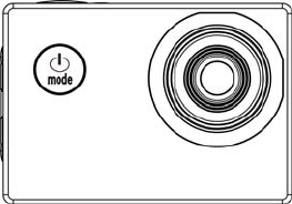
This product is compact in size, and very easy for installation;
The camera supports FHD (1920x1080 25FPS) recording;
Support high-speed USB2.0;
Support 32GB Min SD Card at most;
This product supports video output with playback function; it also supports HD picture.

3
System Requirements
Operating
System
PC Camera Mode (PCCAM) Microsoft System: Microsoft WindowsXP(SP3), Vista, 7, 8
iOS system: MAC OS X Version 10.8.0 or latest version
Removable Disc Mode
(MSDC)
Microsoft System: Microsoft Windows2000, XP, Vista, 7, 8
iOS system: MAC OS X Version: 10.0.0 or latest version
CPU Intel Pentium 1GBHz or CPU with equivalent performance
Internal Memory More than 1GB
Sound card and Graphic card Support DirectX8 or advanced versions.
CD Driver 4x or quicker
Hard Disk Remain more than 2GB memory space
Others USB1.1 or USB2.0 port
4
Appearance
Appearance and
and Buttons
Buttons Introduction
Introduction
5
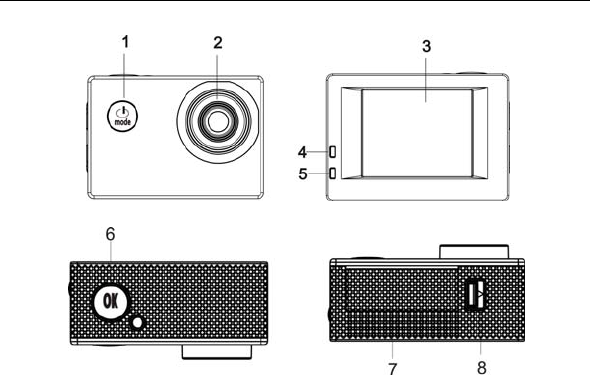
1. On/Off/MODE/Back 2. Lens
3. Display Screen 4. Work Indicator
5. Charging Indicator 6.OK /Menu/Confirm
7. Battery Cover 8. Battery Compartment Switch
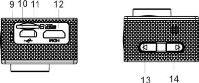
9. Microphone Hole 10. USB Port
11. TF Card Slot 12. HDMI Port
13.T Button (Upper button for Zoom +) 14.W Button (lower button for Zoom-)
6
Initial
Initial Use
Use_______
_______
1. Charge External Lithium Battery
Connect the camera with PC for charging, and the charging indicator (blue) will be on. The indicator will be off
when the charging is completed. Generally, it takes 2-4 hours to fully charge the camera.
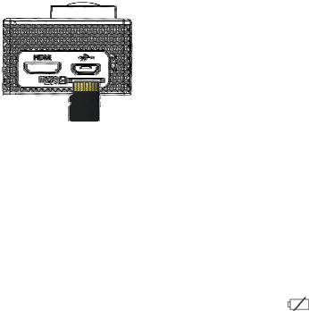
2. Use Storage Card
1. According to the recessed reminder beside the storage card slot, push the TF Card completely into the end.
2. Gently press the rear part of the storage card, and it will automatically pop out.
USB Cable
7
Note: There is no built-in memorizer for this camera. Please insert a storage card when using the camera.
(High-quality TF Card is recommended.)
3. Start up/Shut Down
3.1 Start up: Keep pressing MODE button for 3s, the display screen will be on, and the camera enters Start-up
status.
3.2. Shut down: Under idle mode, press MODE button and hold on 3s to shut the camera down.
3.3. Automatic Shutdown of Screen: When the camera’s idle time is due, the screen will be automatically shut
down for saving power, and the screen shutdown light will be on.
3.4. Shutdown due to Low Power: When its power is extremely low, LCD will display the icon “" ", and
the User shall conduct charging for the camera immediately. When the icon is red and flickering, the camera
will automatically shut down.
8
4. Function Mode Switch
This Camera has 3 modes including video recording mode, photo mode and playback mode. When it is on, press
MODE to switch different modes.
5. Indicator
Work Indicator (Red): When the camera is working (such as recording a video, taking a photo, shutdown and
automatic shutdown of screen etc.), the work indicator will flicker.
Charging Indicator (Blue): During the charging process, this indicator will be on; when the camera is fully
charged, it will automatically go out.
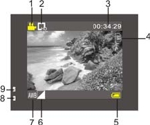
6. Video Recording Mode
When it is powered on, DV will directly enter video recording mode; under the preview status, press OK button
and it will start to record a video; press OK button again, and it will stop video recording. However, video
recording will automatically stop when the storage card is full or the power is extremely low.
1 Mode Icon to indicate Video Recording Mode.
2 It means Video resolution, and FHD 1080P(15FPS)
/ HD 720P(30FPS) / VGA (30FPS) are optional.
3 Recording Time, meaning how much time left for this
Video recording.
4 It means that TF Card is inserted.
5 Battery Icon means current power status.
6 E/V (Exposure Value).
9
7 It means that White Balance is automatic.
8 Charging Indicator.
9 Work Indicator.
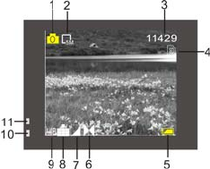
8. Photo Mode:
When it is on, press MODE Button to enter Photo Mode; under the preview status, press OK button to take a
photo:
1 Mode Icon to indicate current Photo Mode.
2 Picture size; click this icon to choose 3M/5M/8M/10M/12M.
3 Counter, meaning the quantity of photo which
can be taken.
4 It means that TF Card is inserted.
5 Battery Power Icon.
6 It means current sharpness.
7 E/V (Exposure Value).
8 It means that the picture quality is Fine.
9 It means that White Balance is automatic.
10 Charging Indicator.
10
11 Work Indicator .
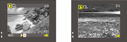
9. Playback Mode:
9.1 Under the preview status, press MODE button twice, and switch to Playback Mode; enter Playback Mode,
and select the file you want to play back via the menu, as shown in the following Figure:
11
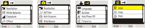
10. Menu Operation:
There are different menus under every work mode, and the following Menus are for your reference:
Video Recording Mode Menu Photo Mode Menu System Setting Mode Menu Playback Mode Menu
Operation: Press OK button for a while, and LCD will display relevant Mode Menu; press OK cursor to select a
Menu, and then press T or W button to move the cursor up or down; press OK again for confirmation, and press
Power button to go back or quit the Menu Mode. Chosen item in the menu will be emphasized with background
color.
12
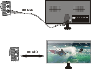
Connect to HD TV:
It is possible to connect the camera to HD TV via HDMI Cable (as shown in the following Figure), and the
display signal of the camera will be automatically transmitted to HD TV, allowing the user to view HD videos or
photos via HD TV.
Dia
g
ram of connection

13
Connect
Connect to
to PC
PC_
______
_____
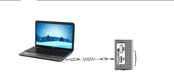
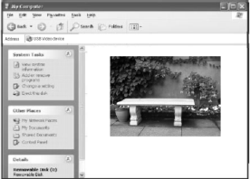
1. The camera is available for usage when plugged; when it is powered on, connect the camera to PC via USB
cable, and it will automatically switch to removable disc mode.
Removable Disc Icon will appear in the window of My Computer. Photos taken by the user will be saved in
I:\jpg folder (I means this device’s Removable Disc), videos recorded in I:\video folder, and Car DVR files in
I:\CAR folder.
Note: If the user wants to enable Removable Disc function via Windows 2000 or more advanced windows
operating system, there is no need to install any drive program.
2. PC CAM Function
The User shall press OK button and Start button at the same time to directly switch to PC CAM mode (PCCAM
will appear on the display screen).
The icon will appear in My Computer. Double click this icon to enable real-time video
function, and the user can use this device to realize PC CAM function.
14
PC CAM Function is available in Windows XP(SP3)/ MAC OS X version: 10.8.0 or more advanced version.

15
Technical
Technical Parameters
Parameters
Image Sensor 1.3 CMOS
Function Mode Video Recording, Photo and Playback Mode
Lens F2.4 f=3.0mm
LCD 1.77 inches LCD
Picture Resolution 12M, 8M, 5M, 3M, 2M, and 1M
Video Resolution FHD: 1920x1080(25fps) interpolation, HD: 1280x720(30fps), VGA:
640x480(30fp)
File Formats Video AVI
Picture JPG
Storage Medium TF Card (32GB at most)
USB Port High-speed USB 2.0 port
Power Supply External 3.7V chargeable lithium battery 400mAh
Dimensions 59x41x24.5mm
16
Label Statement:
This device complies with part 15 of the FCC Rules. Operation is subject to the following two conditions: (1)
This device may not cause harmful interference, and (2) this device must accept any interference received,
including interference that may cause undesired operation.
FCC Statement
This equipment has been tested and found to comply with the limits for a Class B digital device, pursuant to part
15 of the FCC rules. These limits are designed to provide reasonable protection against harmful interference in a
residential installation. This equipment generates, uses, and can radiate radio frequency energy and, if not
installed and used in accordance with the instructions,
may cause harmful interference to radio communications. However, there is no guarantee that interference will
not occur in a particular installation.
If this equipment does cause harmful interference to radio or television reception, which can be
determined by turning the equipment off and on, the user is encouraged to try to correct the

17
interference by one or more of the following measures:
• Reorient or relocate the receiving antenna.
• Increase the separation between the equipment and receiver.
• Connect the equipment into an outlet on a circuit different from that to which the receiver
is connected.
• Consult the dealer or an experienced radio/TV technician for help.
To assure continued compliance, any changes or modifications not expressly approved by the
party responsible for compliance could void the user’s authority to operate this equipment.