Sick STR1 Safety Switch User Manual STR1 8018754
SICK AG Safety Switch STR1 8018754
UserManual.wiki
>
Sick
>
STR1 User Manual
User Manual
Navigation menu
Upload a User Manual
Namespaces
Wiki Guide
HTML
PDF
Info
Views
User Manual
Discussion / Help
Navigation

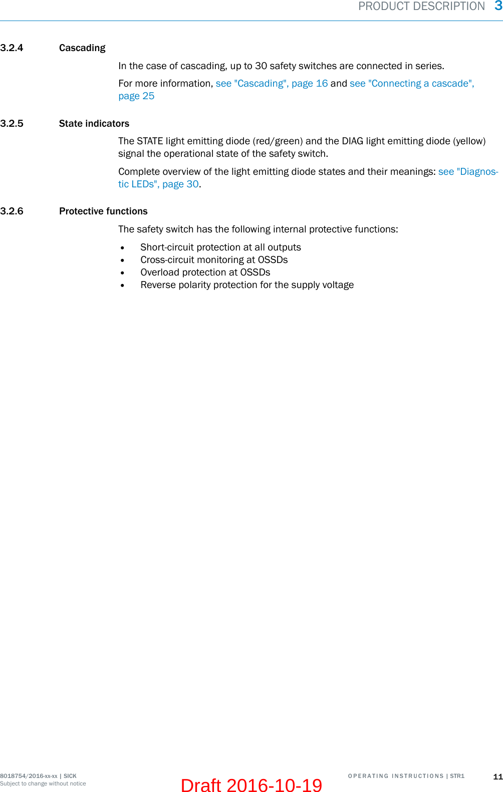
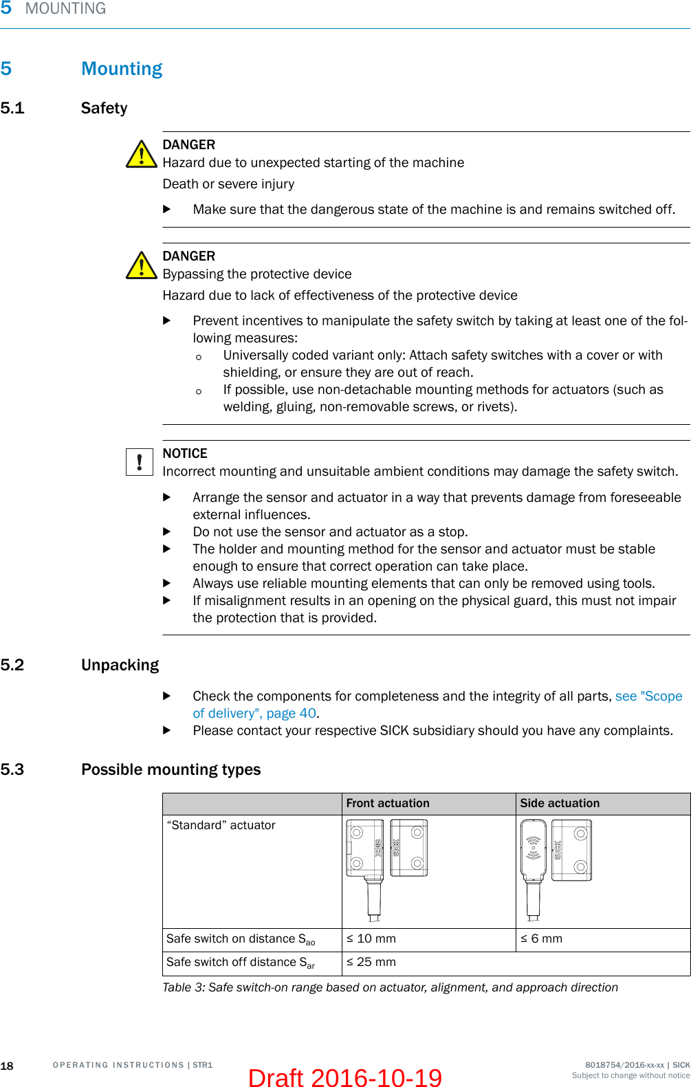
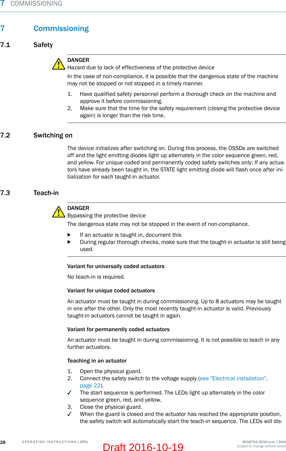
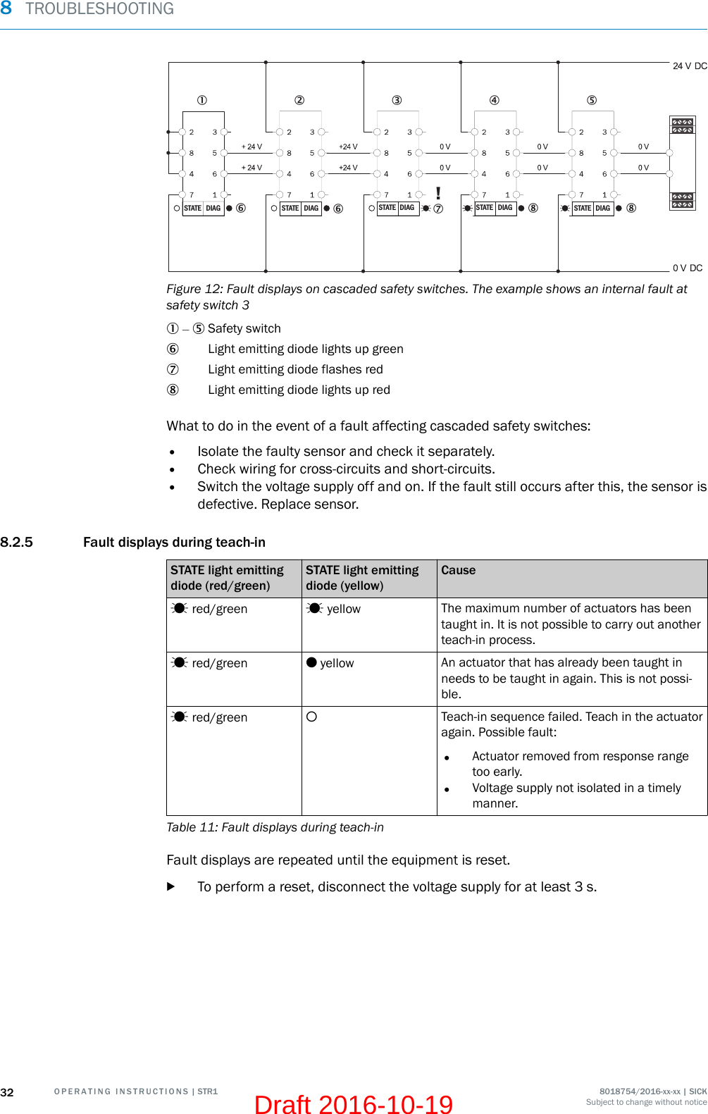
![Front actuation Side actuationSwitch-on behavior with“Standard” actuator relative todirection of approach–40–20204000 4 8 12 16 20[mm]Peripheral zones with parallelapproach. Minimum distance:6 mm–40–20204000 4 8 12 16 20[mm]No peripheral zones. No mini‐mum distance with parallelapproach“Flat” actuatorSafe switch on distance Sao ≤ 14 mm ≤ 9 mmSafe switch off distance Sar ≤ 28 mm“Mini” actuatorSafe switch on distance Sao ≤ 14 mm ≤ 9 mmSafe switch off distance Sar ≤ 28 mmSwitch-on behavior with “Flat”or “Mini” actuator relative todirection of approach–40–20204000 4 8 12 16 20[mm]Peripheral zones with parallelapproach. Minimum distance:10 mm–40–20204000 4 8 12 16 20[mm]Peripheral zones with parallelapproach. Minimum distance:4 mmTable 3: Safe switch-on range based on actuator, alignment, and approach directionMOUNTING 58018754/2016-xx-xx | SICK O P E R A T I N G I N S T R U C T I O N S | STR1 19Subject to change without noticeDraft 2016-10-19](https://usermanual.wiki/Sick/STR1/User-Guide-3169821-Page-19.png)

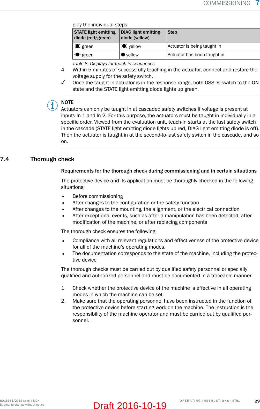

![15.2 FCC and IC radio approval•FCC ID: 2AHDRSTR1•IC: 21147STR1The device fulfills the EMC requirements for use in the USA and Canada, in accordancewith the following extracts from the relevant approvals:FCC § 15.19This device complies with Part 15 of the FCC rules. Operation is subject to the followingtwo conditions:•This device may not cause harmful interference, and•this device must accept any interference received, including interference that maycause undesired operation.FCC §15.21 (warning statement)[Any] changes or modifications not expressly approved by the party responsible for com‐pliance could void the user’s authority to operate the equipment.ICThis device complies with Industry Canada’s licence-exempt RSSs. Operation is subjectto the following two conditions:•This device may not cause interference; and•This device must accept any interference, including interference that may causeundesired operation of the device.Le présent appareil est conforme aux CNR d’Industrie Canada applicables aux appa‐reils radio exempts de licence. L’exploitation est autorisée aux deux conditions sui‐vantes :•l’appareil ne doit pas produire de brouillage;•l’utilisateur de l’appareil doit accepter tout brouillage radioélectrique subi, mêmesi le brouillage est susceptible d’en compromettre le fonctionnement.15 ANNEX46 O P E R A T I N G I N S T R U C T I O N S | STR1 8018754/2016-xx-xx | SICKSubject to change without noticeDraft 2016-10-19](https://usermanual.wiki/Sick/STR1/User-Guide-3169821-Page-46.png)