SISTEMATICA S p A CONTROLLER8 Remote Controlled Outputs Actuator User Manual Receiver CONTROLLER 8 REV 3
SISTEMATICA S.p.A. Remote Controlled Outputs Actuator Receiver CONTROLLER 8 REV 3
manual
SISTEMATICA S.p.A.
SISTEMATICA S.p.A.SISTEMATICA S.p.A.
SISTEMATICA S.p.A.
REV.
REV.REV.
REV.2
22
2
Via S. Pertini, 17 – 12030 MANTA (CN) ITALY Tel. +39 0175 255.711 r.a. – Fax +39 0175 255.715
http://www.sistematica.it e-mail: info@sistematica.it 18/10/2012
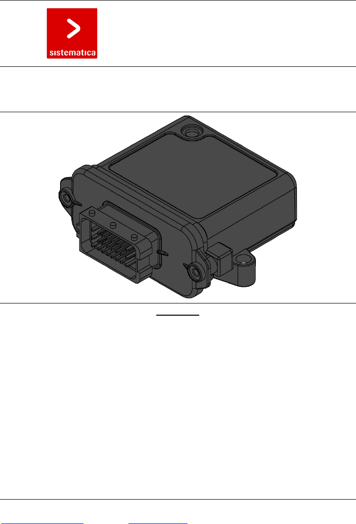
CONTROLLER 8
RADIO REMOTE CONTROL 8 OUTPUTS
USER AND MAINTENANCE MANUAL
WARNINGS
This manual is an essential part of the device and it should be thoroughly kept for later consultation.
Carefully read the warnings contained in this manual, concerning safety and a proper preservation of the
product. These warnings are always to be carefully read before using the device. SISTEMATICA S.p.A.
declines all responsibility for any trouble arising from the non-compliance with these warnings.
• DO NOT TRAVEL WITH THE DEVICE SWITCHED ON
• CONNECT THE SYSTEM ONLY TO THE VEHICLE’S BATTERY
• BEFORE CARRYING OUT ANY MECHANICAL MAINTENANCE OPERATION (WELDING) ON THE
VEHICLE, DISCONNECT THE BATTERY CLIPS.
• AVOID ATTEMPTING TO REPAIR THE DEVICE BY YOURSELF. REPAIRS PERFORMED BY
UNSKILLED PEOPLE CAN CAUSE SERIOUS DAMAGES OR FAILURES. FOR ASSISTANCE,
APPLY TO YOUR LOCAL AUTHORIZED SERVICE CENTRE. USE ONLY ORIGINAL SPARE PARTS.
• ALWAYS KEEP AT A SAFE DISTANCE FROM THE MOVING PARTS.
SISTEMATICA S.p.A.
SISTEMATICA S.p.A.SISTEMATICA S.p.A.
SISTEMATICA S.p.A.
Pag. 2/4
Via S. Pertini, 17 – 12030 MANTA (CN) ITALY Tel. +39 0175 255.711 r.a. – Fax +39 0175 255.715
http://www.sistematica.it e-mail: info@sistematica.it
TECHNICAL FEATURES
• Manufacturer: SISTEMATICA S.p.A.
• Dimensions: 108x110x44
• Outputs number: up to 8
• Digital inputs number: 1
• IP protection: IP66
• Operating temperature: -20°C ÷ +70°C
• Power supply voltage: 12/24 V ±10%
• Current consumption (stanby): - 30 mA at 12 V
- 30 mA at 24 V
• Max current per channel: 5 A
• Max total current: 10 A
• Main connector: FCI-SICMA 24 Header pin
• 8 bit microcontroller
• Reverse battery protection
• Internal antenna
• Emergency keyboard (option)
• Receiver category (EN 300-220-1): 2
SYSTEM CODING
Coding the system is an operation that is only necessary when the receiver has to be replaced or you want to use it
with a different SISTEMATICA radio remote control from the one it is coupled with at the time of purchase.
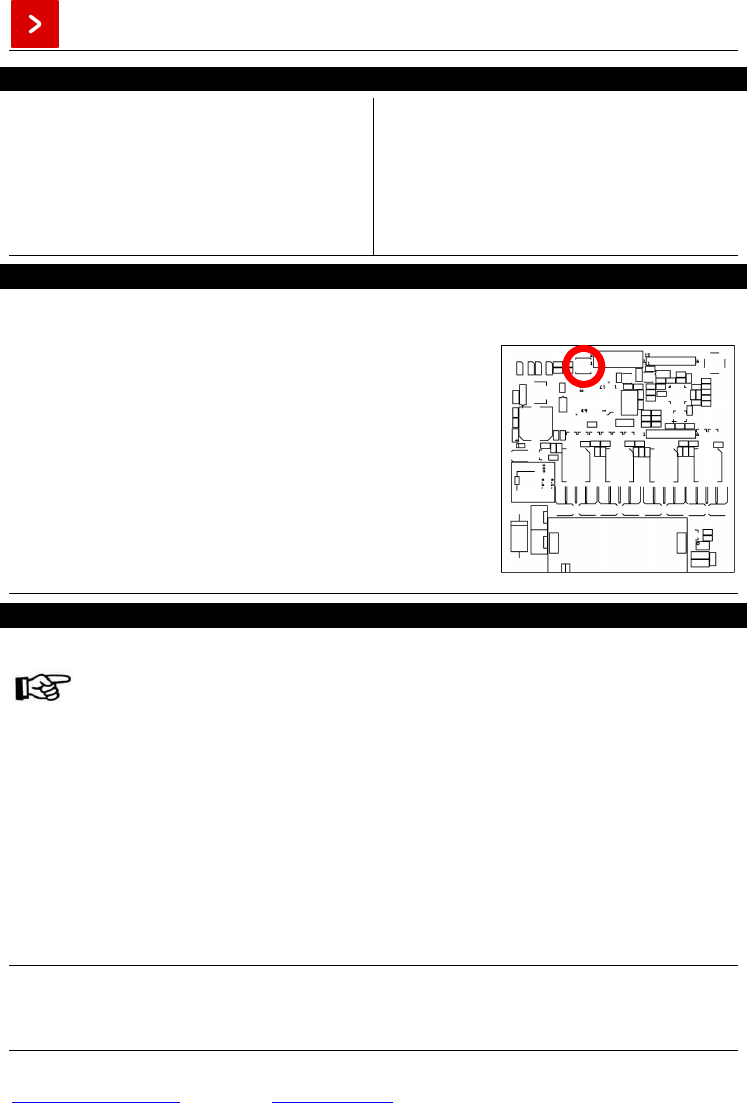
For a correct coding procedure, perform the following steps:
1. Disconnect the power to the receiver;
2. Open the receiver box, by unsrewing the 2 screws at the side of the
connector;
3. Locate and press the coding pushbutton on the receiver board (figure
1);
4. Put power into the receiver by keeping the coding pushbutton pressed
for 3-4 sec.; the yellow led on the receiver board flashes two time per
second; so release the coding pushbutton;
5. Press any 3 keys at the same time on the transmitter within 15 seconds
since it has been switched on (also more time if it is necessary; the
yellow led stop to blink);
6. At this time, the transmitter is codified with the reveiver; check all the
system function by trying the movements of the system;
7. Close the receiver box by screwing the two screw removed at step 2.
Figure 1. Coding pushbutton
RELAY MOTOR RESETTING
The relay motor resetting is an operation to carry out in order to change its coupling with the other outputs (OUT1,
OUT2, OUT3…) from the original standard system setting.
By a standard system setting when any key is pressed on the radio control transmitter the
correspondent output and relay motor output is activated. (see “Instructions for use” in the
radio control transmitter manual).
To change therealy motor output coupling with the output requie, it is necessary to act as follows:
1. Disconnect the power to the receiver;
2. Open the receiver box, by unsrewing the 2 screws at the side of the connector;
3. Put power into the receiver;
4. Press simultaneously the coding button on the receiver board (fig. 1) and START key on the transmitter for 3-4
sec., so release the 2 keys;
5. Activate in a row, by the transmitter, the outputs that are to be coupled with the relay motor;
6. Press simultaneously the coding button on the receiver board (fig. 1) and STOP key on the transmitter for 3-4
sec., so release the 2 keys;
7. At this time the new output and relay motor coupling is recorded; check all the system function by trying the
movements of the system;
8. Close the receiver box by screwing the two screw removed at step 2.
In case any error should occur while resetting the system, it is possible to cancel the operation, by taking the power
off the system and repeating the operation.
SISTEMATICA S.p.A.
SISTEMATICA S.p.A.SISTEMATICA S.p.A.
SISTEMATICA S.p.A.
Pag. 3/4
Via S. Pertini, 17 – 12030 MANTA (CN) ITALY Tel. +39 0175 255.711 r.a. – Fax +39 0175 255.715
http://www.sistematica.it e-mail: info@sistematica.it
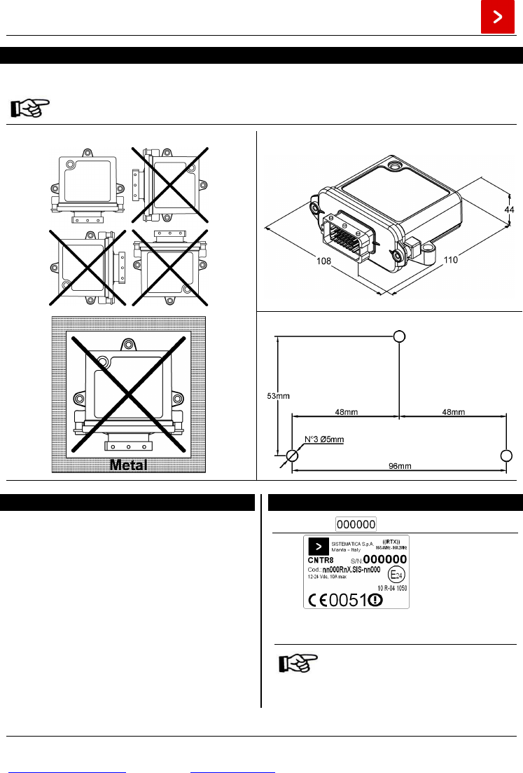
POSITIONING OF THE RECEIVER UNIT, DIMENSION AND DRILLING TEMPLATE
For a proper functioning, locate the receiver type CONTROLLER 20 with the cable output downwards, as shown in
the picture below:
The receiver is provided with an integrated antenna; be sure to locate it at sight, not inside any
metal box or screened by ferrous masses (ex. Protection carter...)
POSITIONING OF RECEIVER UNIT
RECEIVER DIMENSION
DRILLING TEMPLATE DIMENSION
FUSE REPLACEMENT
The system is automatically protected from power
overload and from possible short-circuit on
corresponding outputs. For further protection is also
provided an internal fuse within the box. For replacing
the damaged fuse, please proceed as follows:
1. Disconnect the power to the receiver;
2. Open the receiver box, by unsrewing the 2 screws
at the side of the connector;
3. Locate the damage fuse on the receiver board;
4. Take the damaged fuse out of its holder and insert
the new fuse, (F1= 15 A);
5. Put power into the receiver; to check that the fuse
has been correctly replaced, try one or more
movements of the system;
6. Close the receiver box by screwing the two screw
removed at step 2.
PRODUCT IDENTIFYING LABELS
Internal label
CNTR8: product model
S/N: product serial number
Cod.: product identification number
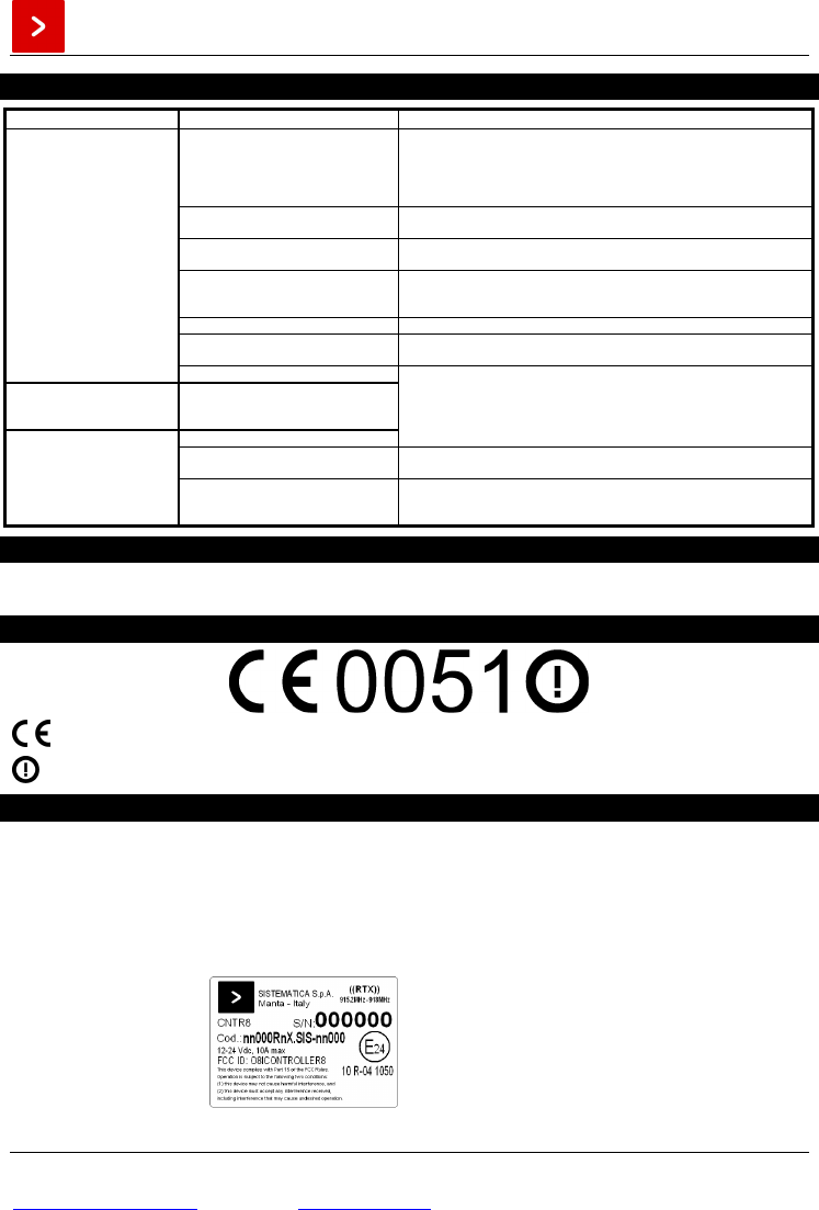
External label
Removal of the identifying labels
entails lapin of the guarantee
conditions and the responsabilità of
SISTEMATICA S.p.A. with respect to
component bodies
SISTEMATICA S.p.A.
SISTEMATICA S.p.A.SISTEMATICA S.p.A.
SISTEMATICA S.p.A.
Pag. 4/4
Via S. Pertini, 17 – 12030 MANTA (CN) ITALY Tel. +39 0175 255.711 r.a. – Fax +39 0175 255.715
http://www.sistematica.it e-mail: info@sistematica.it
PROBLEM IDENTIFICATION AND SOLUTION
P
ROBLEM
POSSIBLE
CAUSES SOLUTIONS
The system does not respond
to the controls
Absence of power in the receiver unit
-Check that the emergency mushroom button on the transmitter (if present)
is in the release position.
-Check that the vehicle batterie is correctly connected to the receiver unit
-Check that the fuse inside the receiver unit is inctact, and if it is not, replace
it (see “FUSE REPLACEMENT”)
Incorrect connection of the cabling to
the utilities -Check the cabling to indicators, electro-valves etc.
Incorrect installation of the receiver -The receiver must not be shielded by ferrous masses (see “POSITIONING
OF THE RECEIVER UNIT”)
Incorrect replacement of the batteries -Check that the batteries have been inserted correctly; if necessary replace
them (see “REPLACEMENT THE BATTERIES” on the manual of the
transmitter combined)
System not coded -Re-code the system (vedi “CODIFYING THE SYSTEM”)
Blown fuse -Replacement of the fuse on the receiver board (see “FUSE
REPLACEMENT”)
Flat batteries
-Replacement of the transmitter batteries (vedi “REPLACEMENT THE
BATTERIES” on the manual of the transmitter combined)
The GREEN led on the
remote control does not light
up when a key is pressed Flat batteries
The system responds to the
controls in a discontinuous
way
Batteries almost flat
Using the transmitter beyond its
maximum range -Keep to a distance ≤ 120m from the receiver
Connection to the battery and to the
utilities made with cables of unsuitable
section or lenght
-Chech that the connection to the battery and the utilities are made with
cables of suitable section and lenght
ANNEX
• Annex A: WIRING
• Annex B: EMERGENCY KEYBOARD (only if receiver with emergency keyboard)
CE MARK
Declaration of conformity for Sistematica S.p.A. products can be required at: info@sistematica.it
This product may be subjected to usage restriction. Please contact info@sistematica.it for any further questions.
FCC STATEMENTS
These devices complies with Part 15 of the FCC rules.
Operation is subject to the following two conditions:
(1) these devices may not cause harmful interference and
(2) these devices must accept any interference received, including interference that may cause undesired operation.
NOTE: The manufacturer is not responsible for any radio or tv interference caused by unauthorized modifications to
these equipment. Such modifications could void the user’s authority to operate the equipments.
SISTEMATICA S.p.A. Grantee Code: O8I
TRENDRTX label example
FCC ID: O8ICONTROLLER8