SK Global 2201699 RADAR DETECTOR User Manual Owner s Manual
SK Global RADAR DETECTOR Owner s Manual
MANUAL

Cat. No. 22-1699
Owner’s Manual
Please read before using this equipment.
360
Laser/Radar Detector

FEATURES
Your RadioShack 360° Laser/Radar detector can alert you
to all known police traffic radar and laser systems with its
distinct visual and audio alerts. It receives X-, K-, and Ka-
band radar signals, and detects both the instant-on and
laser systems many police departments use to measure
vehicle speed. Plus, your detector can give you advance
warning of potential road hazards by detecting signals
from transmitters that broadcast Safety Warning System™
alerts.
Note: Before reading this Owner’s Manual, read the su-
pplied booklet Questions and Answers About Vehicle
Speed Detection to familiarize yourself with the terms and
uses associated with your detector.
Your detector’s features include:
Electric Compass – provides accurate heading
information with alphanumeric display and LED panel.
Real Voice Alert – greets you as you turn on the detector
and alerts you with different vocal indicators including
radar and laser detection.
2000 Tandy Corporation All Rights Reserved
RadioShack is a registered trademark used by Tandy Corporation.
SWS is a trademark of Safety Warning System, Inc.
Compass technology is licensed under US patent numbers 4,851,775 and 5,239,264
from Precision Navigation, Inc.
FAST is a registered trademark used by Tandy Corporation.
Instaclear is a registered trademark used by Ford Motor Company.
ElectriClear is a registered trademark by Libbey, Owens, Ford and Delco-Remy.
2

Alphanumeric Display - appears you turn on the detector
and alerts you with various text messages including radar
and laser detection
360°Detection – detects laser signals from all around
your vehicle.
VG-2 Protection - makes your detector invisible to the
VG-2 radar-detector when it senses VG-2 operation
X-, K-, Ka-Band( Newly Included Ka-POP ), and Laser
Signal Detection - warns you when it detects signals from
traffic radar or laser devices. Different tone and display
indicators let you know the type of signal received.
Safety Warning System Detection - alerts you to the
presence of potential road hazards, and emergency veh-
icles signaled by Safety Warning System transmission.
City/Highway Modes - let you minimize alerts when you
are in areas that have false radar sources.
City/Highway Selector and City/Highway Indicator -
displays which mode is currently selected.
FAST® (False Alert Suppression Technology) - helps
prevent false alarms caused by non-traffic radar sources.
Tutorial Mode – lets you experience how the detector
alerts you with its detection display, tones, and real voice
alert to all of the different signals the detector recognizes.
3

Auto Mute Mode – automatically reduce the audio
volume of all alerts after 4 seconds for as long as the
signal is detected. 3
Memory Retention - retains operational settings in
memory without power, so when you turn on your detector,
the setting will be the same as when you turned it off.
Instant On Radar Protection - alerts you to sudden high
level and radar signals.
Your radar/laser detector includes the following items:
i coiled power cord
i windshield bracket with suction cups
i hook and loop tape
i Spare fuse
i Question and Answer About Vehicle Speed Detection
We recommend you record your detector’s serial number
here. The number is on the detector’s bottom panel.
Serial Number:
Important: Some areas have laws regulating the use of
radar detectors. Check with your local law enforcement
agency about the laws in your area.
4

CONTENTS
A Quick Look …………………….………………………… 6
Installation ……….………………………………………….8
Selecting a Mounting Location ……………………….. 8
Mounting Guidelines ………………………….,…… 8
Windshield Mounting …………………………………... 9
Hook and Loop Mounting …………………………….. 11
Connecting Power ………………………………………. 12
Operation …………………………………………………..13
Turning On the detector ……………………………… 13
Adjusting the Volume …………………………………. 13
Tutorial mode……………………………………………14
ELECTRIC COMPASS…………………………………15
Operating Setting ………………………………………17
Selecting the City and Highway Modes ………… 17
Selecting Display Brightness …………………….. 18
Muting the Audio Alert ………………………….… 18
Auto Mute mode…………………………………….19
Selecting VG-2 Modes …………………..……….. 20
Receiving and Identifying Radar, Laser,
and Safety Alert Signals……………………………… 20
SWS Categories and Messages……………………22
Troubleshooting …………………………………………..25
Care and Maintenance ………………………………….. 27
Replacing the fuse ……………………………………. 28
5
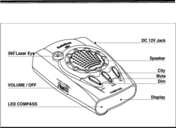
A QUICK LOOK
1. 360˚Laser Eye – receives incoming laser signals
directed at your vehicle from all directions.
2. DC 12V Jack – the power cord plugs in here.
3. DIM Button – controls the brightness of alphanumeric
display.
4. Mute Button – silences the alert tone for about 20
seconds after the current signal is lost.
5. City (City/Highway) Button – switches between the
city and highway modes.
6

6. Speaker – sounds a digital voice alert and tones let you
know the types of radar and laser signals detected
7. LED Compass – indicates your headinginformation.
8. High Visibility Alphanumeric Display - provides di-
stinct visual of signal detected, signal strength, and he-
ading information, and indicates the selected operating
mode.
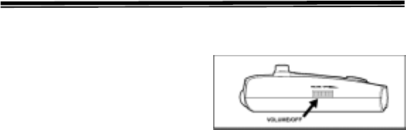
9. VOLUME/OFF Control – turns the detector on and off
and lets you adjust the volume.
SAFETY WARNING ® SYSTEM ™
The revolutionary Safety Warning System (SWS) has won
formal approval from the Federal Communications Comm-
ission (FCC) to operate on the 24.05 ~ 24.25 GHz band
for highway safety alerting and traffic signal control
purposes.
The Safety Warning System employs low-powered trans-
mitters used by some emergency services and road crews
to alert drivers to hazardous road conditions. The SWS
can indicate many different emergency or hazardous
condition in the area ( 60 different messages are currently
defined, with 3 additional messages for future use).
The system has the potential to dramatically decrease the
occurrence of traffic accidents by increasing driver’s
awareness of local road hazards. Having this safety alert
compatible radar/laser detector will ensure that you can
benefit from this system wherever it is in use. 7

INSTALLATION
SELECTING A MOUNTING LOCATION
For the best performance, select a location for the dete-
ctor where it has a direct view of the road. The detector’s
radar antenna is at the opposite end from display.
Note: Though the detector has a 360°laser and radar
detection range, the radar detection is more sensitive in
the front range.
Mounting Guidelines
Follow these guidelines when selecting a location.
iChoose a location that does not block the driver’s
view of the road.
iMount the detector in a level position with a clear
view to both the front and rear of your vehicle.
iThe detector’s view of road must not be blocked by
any metal object.
iSome vehicle have InstaClear® or ElectriClear® def-
ogging windshield, which have metal coatings that
block signals. General Mortor’s APV vans have a solar
shield that keeps the vehicle cooler during the summer,
but also blocks signals. A detector installed in a vehicle
with any of these features will probably not detect a
signal.
8

iSince window tinting reduces the reception strength of
laser signals, you should not mount the detector behind
any tinted glass.
iDo not mount the detector where the driver or a
passenger might hit it during a sudden stop or accident.
Caution: However you choose to mount the detector,
place it out of view when you leave the vehicle. This keeps
the detector out of sight of thieves and prevents exposing
it to extremely high temperatures, which can temporarily
impair your detector’s performance.
WINDSHIELD MOUNTING
The supplied suction-cup windshield bra-
cket lets you easily mount the detector on
the windshield.
Caution: Do not use the bracket in a vehicle that has a
plastic coating on the windshield designed to protect
passengers during an accident. If you use the bracket on
this type of windshield, you might permanently mar the
windshield’s surface. For an alternative mounting method,
see “Hook-and-Loop Mounting” on page 11. .
9
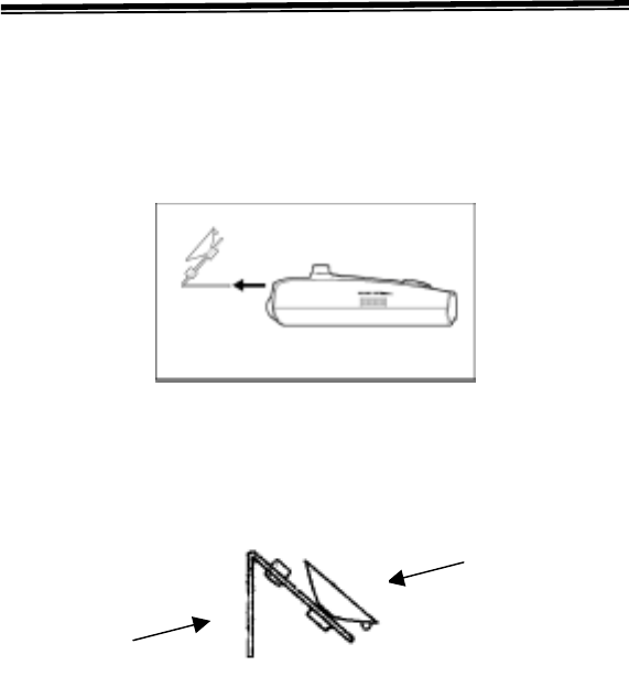
1. Clean the selected windshield area, position the bracket
on the windshield, and press firmly on each suction cup to
secure it in place.
2. Slide the detector onto the base plate until it snaps into
place.
If it is necessary to adjust the mounting the mounting
angle, remove the detector from the bracket. Then,
remove the bracket from the windshield. Adjust the
bracket the bracket by carefully bending it.
10
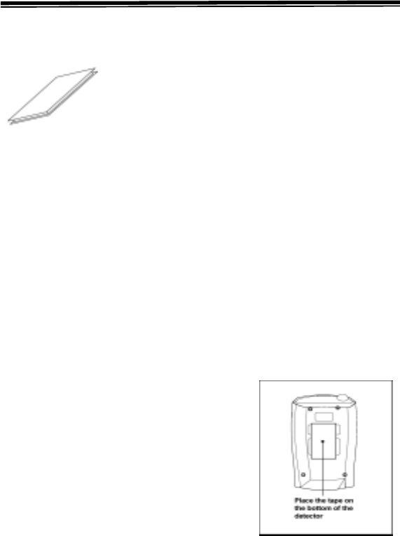
HOOK-AND-LOOP MOUNTING
In some vehicles, the dashboard may be
the best location to mount the detector.
For this mounting, use the supplied hook-
and-loop tape. Follow these steps to use
the hook-and-loop tape.
1. Use a damp cloth to thoroughly clean the bottom of the
stand and the dashboard. Let both surfaces dry.
Note: The tape’s adhesive might not stick to a surface
treated with vinyl cleaner or protectant.
2. Remove the tape’s paper backing and stick the tape to
the bottom of the detector.
Notes : On a curved dashboard, you might need to cut
the hook and loop tape in half and use one strip on each
side of bottom of the stand.
Remove the paper backing
from the other side of the tape
and press your detector onto the
dashboard.
11

CONNECTING POWER
Caution:
i Use only the supplied power
cord. If you power cord is lost or
damaged, you can order a
replacement cord form your local RadioShak store.
iBefore plugging the power cord’s cigarette-lighter
plug into your vehicle’s cigarette-lighter socket, make
sure the plug’s tip is screwed firmly onto the plug. See
“Replacing the Fuse” on Page 26 for more infor- mation
about the cigarette-lighter plug.
i Unplug the power cord’s cigarette-lighter plug from
your vehicle’s cigarette-lighter socket when you turn off
the ignition. This prevents your vehicle’s battery from
being drained if you leave the detector on when you
turn off the ignition.
Plug the supplied power cord’s barrel plug into the
detector’s DC 12V jack. Then plug the cord’s cigarette-
lighter plug into your vehicle’s cigarette-light socket.
Note : If the detector does not operate when you turn it on,
remove the cigarette-lighter plug from your vehicle’s
socket and check the socket for ashes and other debris.
Also, check the fuse in the cigarette-lighter plug and your
vehicle’s fuse block (see “Replacing the Fuse: on Page
26 ).
12
OPERATION
TURNING ON THE DETECTOR
To turn on the detector,
rotate the VOLUME/OFF to-
ward VOLUME until it clicks.
The detector sounds a tone,
and greets you with its voice alert – “Welcome! Buckle
your seat belt,” and a test message – WELCOME !. After
self-testing, heading information and HWY appears on the
alphanumeric display. (See “Selecting the City and
Highway Modes” on page 17)
To turn off the detector, rotate the VOLUME/OFF towards
OFF until it clicks and alphanumeric display turns off.
ADJUSTING THE VOLUME
Rotate VOLUME/OFF toward VOLUME to increase the
detector’s volume, rotate it toward OFF to reduce the
volume.
13

TUTORIAL MODE
Your detector has the tutorial mode to demonstrate all of
its alphanumeric display. In the tutorial mode, you can
check the status of all the alphanumeric display.
Starting the Tutorial Mode
To start the tutorial mode, turn on the detector while
holding down DIM and CITY. The tutorial mode starts with
3 beep sounds when TUTORIAL and MODE flash
alternately.
Selecting the demonstration for Each Alert
To select the demonstration for each alert, press DIM. The
detector display each alert along with its corresponding
audio alert. The detector demonstrates the alerts in the
order of 1 to 11 as shown below.
1. X-Band Alert 8. VG-2 ALert
2. K-Band Alert 9. Rock Slide Area Ahead
3. Ka-Band Alert 10. School Zone Ahead
4. Pro Laser Alert 11. Road Narrow Ahead
5. Pro Laser3 Alert 12. Sharp Curve Ahead
6. LTI-2020 laser alert 13. .Pedestrian Crossing Ahead
7. UltraLyte Laser Alert
Finishing the Tutorial Mode
To finish the tutorial mode, press CITY at any time.
14

ELECTRIC COMPASS
Your radar detector has an electronic compass that can
display 8 different headings:
N, E, S, W, NE, NW, SE, SW
Note: The detector displays the electronic compass
heading information until it picks up a signal. After the
detector displays the signal, it returns to the electronic
compass display.
Calibratiing the Electronic Compass
You must calibrate the electronic compass in your area
before using it. The calibration allows the electronic
compass to separate the earth’s magnetic field from the
magnetic fields generated by external influences such as
your vehicle so that the electronic compass provides
accurate heading information.
Before beginning the calibration, you must install the
detector in your vehicle. See “Installation” on Page 9. The
calibration is best performed on a leveled section of
pavement, such as an empty parking lot.
Note : compass should not be calibrated under the cond-
itions such as underground parking garage, around a
metal structure, etc, so that the customer will know to do
this in a open environment away from such obstacles.
15

When to Calibrate Your Unit
You must calibrate when :
1. It is being used for the first time.
2. It is being used in a different location.
Follow these steps to calibrate your detector.
1. Press CITY button for more than 2 seconds until the
voice says “Please turn your vehicle twice” with 3 beep
sound and “CAL….” Appears; then TURN and TWICE
flash alternately.
2. With the detector mounted in your vehicle, turn the
steering wheel all the way to the right or left and
continue driving in a circular motion. Then press
CITY.
3. After WAIT flashes 4 times, if the calibration is
complete, SUCCESS! Appears and the voice says
“Calibration complete.”
After calibration, the heading appears.
Note: To achieve calibration, two circles must be made
and it must be performed on a levelled surface in less
than 2 minutes.
16

OPERATING SETTINGS
Selecting the City and Highway Modes
Your detector has two operating modes: city and high- way.
In city mode, the detector requires a stronger X-band
signal before it sounds or displays an alert.
Notes:
i City Mode helps prevent false alerts in tightly popu-
lated areas where laser/radar signals can bounce off
surrounding structure.
i The city mode has no effect on laser alerts or K/Ka -
band signal.
The highway mode provides maximum sensitivity for
open-road driving. The detector is preset to highway mode
and HWY appears on the display when you turn it on.
To select the City Mode, press CITY. The voice says “City
mode,” and “CTY” appears on the display.
To return to the highway mode, press CITY again. The
vocie alert says “Highway mode,” and “HWY” appears on
the display again.
17

Selecting Display brightness
You can select from three levels of brightness for your
radar detector: bright, dim, and dark.
Once you set the display brightness, the detector retains
the setting until you change it. Pressing DIM once
reduces the display’s brightness by half. The vocie alert
says “Display dim.” Pressing DIM a second time reduces
the display’s brightness by 90%; the voice alert says
“Display dark.” Pressing Dim a third time returns the
display to full brightness; the voice alert says “Display
bright.”
Muting the Audio Alert
While the detector sounds a radar or Safety alert signal,
press MUTE to temporarily silence the detector. When you
press MUTE, the voice alert says “Mute on”. The detector
automatically resets the mute to off 20 seconds after the
radar or safety alert signal stops. Or, press MUTE again
before it resets, and the voice alert says “Mute off”
18

Auto Mute Mode
Auto Mute mode will automatically reduce the audio
volume of all alerts after 4 seconds for as long as the
signal is detected. The factory setting for Auto Mute is ON
Auto Mute On/Off
When Radar is on stand-By, press MUTE temporarily
while no alert is occurring. Auto Mute will be off with 2
beep sound and A disappear on the display. If Auto Mute
is set to ON, press MUTE again. Auto Mute will be on with
1 beep sound and A appears on the display.
A H W Y
Auto Mute Repeat-Delay Fuction.
When Auto Mute is on, if same radar signal is detected
within 10 seconds again, reduced audio-volume is mainta-
ined.
19
Selection VG-2 modes
VG-2 mode is pre-set to on. To turn off VG-2, hold down
MUTE until the voice alert says, “VG-2 Off” and “VG2-
OFF” appears on the display.
To turn VG-2 on, hold down MUTE until the voice alert
says, “VG-2 On” and “VG2-ON” appears on the display.
RECEIVING AND IDENTIFYING
RADAR, LASER, AND SAFETY ALERT
SIGNALS
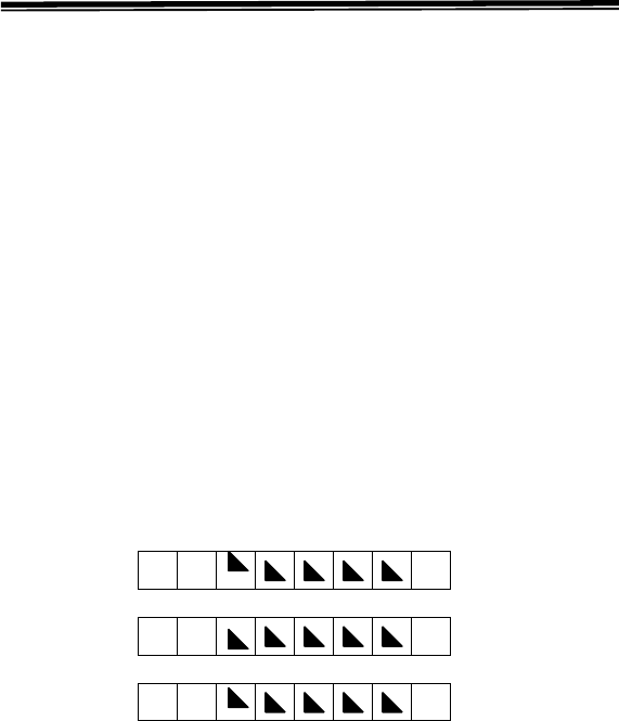
When your detector senses a radar signals, X, K, or KA
( Newly included Ka-POP )appears. An alert tone for the
type of band detected sounds, and the display shows the
signal strength in numeric form.
X 9
K 9
K A 9
Note: The closer you get to the source of the radar, the
higher the signal strength number increases.
20

For radar signal detection, if the signal strength nember
goes higher than 1, the voice alert says. “X-band dete-
cted”, “K-band detected”, or “KA-band detected” respec-
tively.
When your detector senses the laser signal, “PRO
LASER“, “PRO LASER3”, “LTI-2020 LASER” or
“ULTRALYTE LASER” scrolls and voice alert says,
“ Laser detected”.
When VG-2 is detected, “VG-2” flashes and the voice alert
says, “VG-2 detected”.
When your detector senses a SWS signal, a message
appears depending on which SWS signal is detected, an
alert tone sounds for the type of signal detected, and the
voice alert announces the message.
21

SWS Categories and Messages
Category 1
Highway Construction Maintenance
1) WORK ZONE AHEAD
2) ROAD CLOSED AHEAD / FOLLOW DETOUR
3) BRIDGE CLOSED AHEAD / FOLLOW DETOUR
4) HIGHWAY WORK CREW AHEAD
5) UNTILITY WORK CREA AHEAD
6) ALL TRAFFIC FOLLOW DETOUR AHEAD
7) ALL TRUCKS FOLLOW DETOUR AHEAD
8) ALL TRAFFIC EXIT AHEAD
9) RIGHT LANE CLOSED AHEAD
10) CENTER LANE CLOSED AHEAD
11) LEFT LANE CLOSED AHEAD
12) - For future use
Category 2
Highway Hazard Zone Advisory
13) STATIONARY POLICE VEHICLE AHEAD
14) TRAIN APPROACHING / AT CROSSING
15) LOW OVERPASS AHEAD
16) DRAW BRIDGE UP
17) OBSERVE BRIDGE WEIGHT LIMIT
18) ROCK SLIDE AHEAD
19) SCHOOL ZONE AHEAD
20) ROAD NARROWS AHEAD
21) SHARP CURVE AHEAD
22) PEDERSTRAIN CROSSING AHEAD
Category 3
Highway Hazard Zone Advisory
23) DEER/MOOSE CROSSING
24) BLIND/DEAF CHILD AHEAD
25) STEEP GRADE AHEAD/TRUCK USE LOW GEAR
26) ACCIDENT AHEAD
22

27) POOR ROAD SURFACE AHEAD
28) SCHOOL BUS LOADING/UNLOADING
29) NO PASSING ZONE
30) DANGEROUS INTERSECTION AHEAD
31) STATIONARY EMERGENCY VEHICLE AHEAD
32) - For future use
Category 4
Weather Related Hazards
33) HIGH WIND AHEAD
34) SEVERE WEATHER AHEAD
35) HEAVY FOG AHEAD
36) HIGH WATER/FLOODING AHEAD
37) ICE ON BRIDGE AHEAD
38) ICE ON ROAD AHEAD
39) BLOWING DUST AHEAD
40) BLOWING SAND AHEAD
41) BLOWING SNOW WHITE OUT AHEAD
42) - For future use
Category 5
Travel Information/Convenience
43) REST AREA AHEAD
44) REST AREA WITH SERVICE AHEAD
45) 24 HOUR FUEL SERVICE AHEAD
46) INSPECTION STATION OPEN
47) INSPECTION STATION CLOSED
48) REDUCE SPPED AREA AHEAD
49) SPEED LIMIT ENFORCED
50) HAZADOUS MATERIALS EXIT AHEAD
51) CONGESTION AHEAD/EXCEPT DELAY
52) EXPECT 10 MINUTE DELAY
23

Category 6
Travel Information/Convenience
53) EXPECT 20 MINUTE DEALY
54) EXPECT 30 MINUTE DEALY
55) EXPECT 1 HOUR DEALY
56) TRAFFIC ALERT/TURN AM RADIO
57) PAY TOLL AHEAD
58) TRUCKS EXIT RIGHT
59) TRUCKS EXIT LEFT
60) - For future use
Category 6
Fast/Slow Moving Vehicles
61) EMERGENCY VEHICLE IN TRANSIT
62) POLICE IN PURSUIT
63) OVERSIZED VEHICLE IN TRANSIT
64) SLOW MOVING VEHICLE
24

TROUBLESHOOTING
If you have problems operating your detector, the sug-
gestions in this section might help. If you can not solve
the problem after trying these suggestions, take your
detector to your local RadioShack store for assistance.
Problem Suggestion
Be sure all power connections are
secure.
The cigarette-lighter socket might be
dirty. Clean it with fine emery cloth to
ensure a good, clean connection.
Check the fuse in the power cord’s
cigarette-lighter plug. See “Replac-
ing the Fuse” on Page 28.
The detector does not
turn on.
Check the fuse that controls power
to your vehicle’s cigarette-lighter
socket. See your vehicle’s owner’s
manual.
Caution: Do not place any metal object other than the ciga-
rette-lighter or cigarette-lighter plug in the cigarette-lighter
socket. Doing so could blow a fuse in your vehicle or cause the
metal object to become very hot
25

Problem Suggestion
Check the vehicle’s electrical sys-
tem for loose connection, includ-
ing the main battery cable and
alternator connections
The detector gives a
false alert when you use
vehicle accessories such
as power windows,
motorized mirror,
brakes, and so on Install a filter capacitor (1000µF, 35
volts, such as RadioShack Cat. No.
272-1032) on the back of the
cigarette lighter socket, across the
power connections
A police car might not be equipped
with radar (see the supplied bookle-
t, Questions and Answers About
Vehicle Speed Detection)
The detector performs
the self-test, but does
not respond to radar
signals when you see a
police car Police might be using VASCAR
type speed detection (See the
supplied booklet, Questions and
Answers About Vehicle Speed
Detection).
Be sure the laser detection lens is
not blocked.
Be sure the detector is properly
mounted. See “Selecting a moun-
ting Location” on Page 8.
The detector has poor
laser detection range
Use lens cleaning solution to
clean the laser detection lens.
26

CARE AND MAINTENANCE
Your Radio Shack 360˚Laser/Radar detector is an
example of superior design and craftsmanship. The
following suggestions will help you care for the detector so
you can enjoy it for years.
i Keep the detector dry. If it gets wet, wipe it dry
immediately. Liquids can contain minerals that can
corrode the electrical circuits.
i Keep the detector away from dust and dirt,which
can cause premature wear of parts.
i Handle the detector gently and carefully. Dropp- ing
it can damage circuit boards and the case and can
cause detector to work improperly.
i Wipe the detector with a damp cloth occationally to
keep it looking new. Do not use harsh che- micals,
cleaning solvents, or strong detergents to clean it.
Modifying or tampering with the detector’s internal co-
mponents can cause a malfunction and might invalidate its
warranty. If your detector is not operating as it should, take
it to your local Radio Shack store for assisstance
27
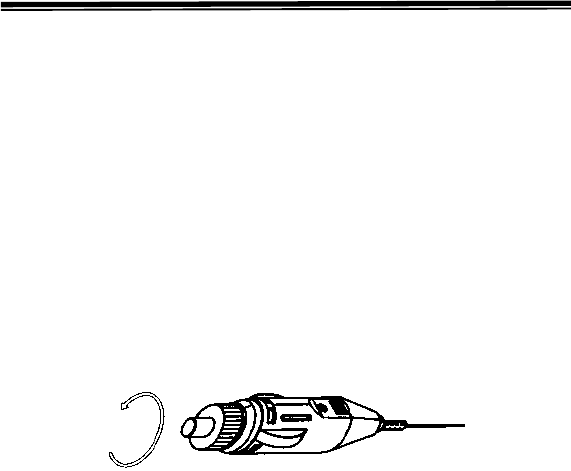
REPLACING THE FUSE
If the detector stops operating, follow these steps to check
the fuse in the power cord’s cigarette lighter plug and
replace it with a 2 amp, 1 1/4 X 1/4, fast-acting fuse
(Cat.No. 270-1007), if necessary.
Caution: Using a fuse that does not meet these require-
ment listed above can damage your detector, the power
cable, or the vehicle’s electrical system.
1. Carefully turn the knurled ring on the cigarette lighter
plug counterclockwise to unscrew it.
Caution: If you must use pliers to loosen the ring, be
careful not to crush the ring or the metal tip inside the ring.
2. Carefully remove the ring and tip from the cigarette
lighter plug, then remove the old fuse.
Note: Take care not to lose the ring or tip, or the spring
inside the plug.
3. Check the fuse. If it has blown, replace it.
28
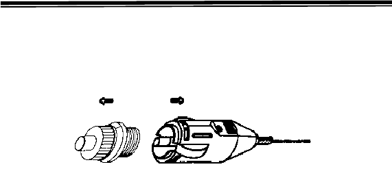
4. Replace the metal tip inside the ring, make sure the
spring is intact, then place the fuse inside the cigarette
lighter plug and screw the ring back onto the plug. Make
sure the tip is visible when you reassemble the cigarette
lighter plug.
Caution : Never use pliers or other tools to retighten the
ring on the cigarette lighter plug.
FCC STATEMENT
This device complies with Part 15 of the FCC Rules.
Operation is subject to the following two conditions:
(1) this device may not cause harmful interference and
(2) this device must accept any interference received,
including interference that may cause undesired
operation.
NOTE: THE MANUFACTURER IS NOT RESPONSIBLE
FOR ANY RADIO OR TV INTERFERENCE CAUSED BY
UNAUTHORIZED MODIFICATIONS TO THIS EQUIP-
MENT. SUCH MODIFICATIONS COULD VOID THE
USER’S AUTHORITY TO OPERATE THE EQUIPMENT.
29