SK Telesys SKSN-I15-CO iDEN RF Repeater User Manual
SK Telesys Co.,Ltd. iDEN RF Repeater
Users Manual

i-DEN REPEATER
SK Telesys Co., LTD Proprietary Document 1/46
i-DEN RF
R
EPEATE
R
USER MANUAL
Version 1.0
2007

i-DEN REPEATER
SK Telesys Co., LTD Proprietary Document 2/46
Lists of Contents
1. OVERVIEW .................................................................................................................3
2. COMPONENTS...........................................................................................................3
2.1 PACKING LIST ......................................................................................................3
2.2 SYSTEM QUICK VIEW .........................................................................................3
2.3 WARNING AND HAZARDS ...................................................................................3
3. FEATURES AND SPECIFICATION OF SYSTEM.......................................................3
3.1 ELECTRICAL SPECIFICATION ................................................................................3
3.2 MECHANICAL SPECIFICATION ...............................................................................3
3.3 ENVIRONMENT SPECIFICATION ............................................................................3
3.4 FREQUENCY USED .................................................................................................3
4. SYSTEM BLOCK DIAGRAM......................................................................................3
4.1 BLOCK DIAGRAM.................................................................................................3
4.2 BLOCK DIAGRAM DESCRIPTION .......................................................................3
5. SYSTEM OVERVIEW..................................................................................................3
5.1 CONSTRUCTION AND FEATURES OF SYSTEM ................................................3
5.1.1 PSU (POWER SUPPLY UNIT) ..............................................................................3
5.1.2 CONTROLLER ......................................................................................................3
5.1.3 UP / DOWN CONVERTER ....................................................................................3
5.1.4 MULTIPLEXER ......................................................................................................3

i-DEN REPEATER
SK Telesys Co., LTD Proprietary Document 3/46
5.1.5 PAU(POWER AMPLIFIER UNIT)...........................................................................3
5.1.6 CABINET ...............................................................................................................3
5.2 ADDITIONAL FUNCTIONS ...................................................................................3
5.2.1 ALC FUNCTION ....................................................................................................3
5.2.2 SHUTDOWN FUNCTION ......................................................................................3
5.2.3 OSCILLATION CHECK FUNCTION ......................................................................3
5.2.4 OSCILLATION SHUTDOWN FUNCTION..............................................................3
6. SYSTEM INSTALLATION GUIDE...............................................................................3
7. WEB GUI INSTALLATION GUIDE..............................................................................3
7.1 PROGRAM SETUP ...............................................................................................3
7.2 WEB GUI CONNECTION ......................................................................................3
7.3 MONITOR/CONTROL OF WEB GUI STATE .........................................................3
7.3.1 ACCOUNT.............................................................................................................3
7.3.2 USER REGISTRATION .........................................................................................3
7.3.3 DELETION AND CHANGE OF USER ...................................................................3
7.3.4 ALARM HISTORY..................................................................................................3
7.3.5 CONFIG.................................................................................................................3
7.3.6 UP LOAD ...............................................................................................................3
8. MAINTENANCE GUIDE..............................................................................................3
8.1 CONFIRMATION OF SYSTEM COMPONENTS ...................................................3
8.2 CAUTIONS ON SYSTEM INSTALLATION ............................................................3

i-DEN REPEATER
SK Telesys Co., LTD Proprietary Document 4/46
9. SYSTEM SET UP AND INSPECTION ........................................................................3
9.1 ITEMS TO BE CHECKED FOR OPENING............................................................3
9.2 ITEMS TO BE CHECK AFTER OPENING.............................................................3
9.3 FAILURE AND INSPECTION.................................................................................3
9.3.1 INSPECTION OF REPEATER...............................................................................3
9.3.2 FACILITY INSPECTION ........................................................................................3
10 . WARRANTY AND REPAIR POLICY........................................................................3
10.1 GENERAL WARRANTY ........................................................................................3
10.2 LIMITATIONS OF WARRANTY .............................................................................3
10.3 LIMITATION OF DAMAGES ..................................................................................3
10.4 NO CONSEQUENTIAL DAMAGES .......................................................................3
10.5 ADDITIONAL LIMITATION ON WARRANTY .........................................................3
10.6 RETURN MATERIAL AUTHORIZATION (RMA) ....................................................3
☎ CONTACT INFORMATION........................................................................................3
Information in this document is subject to change without notice.
SK Telesys Co., LTD. All rights reserved.

i-DEN REPEATER
SK Telesys Co., LTD Proprietary Document 5/46
- Lists of Figures -
< Fig. 1 > Configuration of iDEN Network ................................................................................. 3
< Fig. 2 > Components of iDEN Repeater................................................................................. 3
< Fig. 3 > Front & Back View of iDEN Repeater........................................................................ 3
< Fig. 4 > Side View of iDEN Repeater ..................................................................................... 3
< Fig. 5 > Bottom View of iDEN Repeater................................................................................. 3
< Fig. 6 > iDEN Frequency........................................................................................................ 3
< Fig. 7 > Features of iDEN Carrier........................................................................................... 3
< Fig. 8 > Block Diagram........................................................................................................... 3
< Fig. 9 > Internal Construction of iDEN Repeater.................................................................... 3
< Fig. 10 > Bottom View of iDEN RF Repeater ......................................................................... 3
< Fig. 11 > Latch Structure ........................................................................................................ 3
< Fig. 12 > Hinge Functions ...................................................................................................... 3
< Fig. 13 > Swing Handle Function ........................................................................................... 3
< Fig. 14 > Guide for Wrench Prevention .................................................................................. 3
< Fig. 15 > Mounting Sequence of the iDEN Repeater ............................................................. 3
< Fig. 16 > Local Area Connection Properties........................................................................... 3
< Fig. 17 > Internet Protocol(TCP/IP) Properties ...................................................................... 3
< Fig. 18 > Local Area Connection State-1................................................................................ 3
< Fig. 19 > Local Area Connection State-2................................................................................ 3
< Fig. 20 > Web GUI Initial Screen............................................................................................ 3
< Fig. 21 > Monitoring Screen of iDEN Repeater State............................................................. 3
< Fig. 22 > Control Screen of iDEN Repeater State.................................................................. 3
< Fig. 23 > Input Range Excess Message ................................................................................ 3
< Fig. 24 > Set Up Completion Message .................................................................................. 3
< Fig. 25 > Polling Time............................................................................................................. 3
< Fig. 26 > Function Button ....................................................................................................... 3
< Fig. 27 > Logout ..................................................................................................................... 3
< Fig. 28 > Account Page .......................................................................................................... 3
< Fig. 29 > User Registration .................................................................................................... 3
< Fig. 30 > Deletion and Change of User.................................................................................. 3
< Fig. 31 > Alarm History........................................................................................................... 3

i-DEN REPEATER
SK Telesys Co., LTD Proprietary Document 6/46
< Fig. 32 > Construction Information of System ........................................................................ 3
< Fig. 33 > Upload Page ........................................................................................................... 3
< Fig. 34 > File Selection........................................................................................................... 3
< Fig. 35 >Upload Arrangement ................................................................................................ 3
< Fig. 36 > Key Value Error ....................................................................................................... 3
< Fig. 37 > Upload Completion.................................................................................................. 3
- Lists of Tables -
<Table 1 > Packing List ............................................................................................................. 3
<Table 2 > System Features ..................................................................................................... 3
<Table 3 > Figure and Function................................................................................................. 3
< Table 4 > Environmental specifications .................................................................................. 3
< Table 5 > iDEN Frequency ..................................................................................................... 3

i-DEN REPEATER
SK Telesys Co., LTD Proprietary Document 7/46
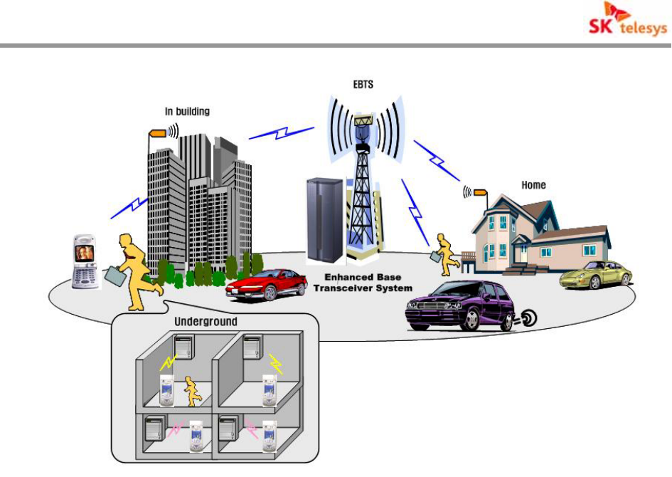
1. Overview
iDEN (Integrated Digital Enhanced Network) repeater is an OTA type of repeater based on RF
signal boosting to enhance in-building coverage using frequency bandwidths operated by iDEN
system.
iDEN repeater amplifies received EBTS(Enhanced Base Transceiver System) OTA signal and
relays it to fill an in-building coverage. The amplified signal can be distributed by repeaters
installed in various poor coverage where telecommunication service can not be provided such
as buildings, homes and in-building parking lots..
It is designed to be flexibly applicable for every frequency in iDEN spectrum bandwidth with
excellent selectivity capabilities of frequency in broad range for Down Link and Up Link service
through one UP/DOWN Converter and minimizes interference of other signals. For stable
service of repeater installed in the field iDEN (Integrated Digital Enhanced Network) repeater
controller has two management functions; the local repeater management function to
continuously manage and control the repeater and remote repeater management function to
remotely inspect and control through intensive inspection system.
iDEN (Integrated Digital Enhanced Network) repeater is interlocked with iDEN repeater
intensive inspection system using modem.
The basic structure of iDEN repeater is supported by one input Port and one output Port. The
inner section of repeater composes of One-Module of DL(Down Link) Converter and UL(Up
Link) Converter, PSU(Power Supply Unit), Multiplexer, Controller, and PAU(Power Amplifier
Unit) in order to achieve optimized size and high effectiveness.
All modules except PAU are commonly used for cost effective operation. For instance
replacement of PAU enables change of repeater output.
i-DEN REPEATER
SK Telesys Co., LTD Proprietary Document 8/46
< Fig. 1 > Configuration of iDEN Network
i-DEN REPEATER
SK Telesys Co., LTD Proprietary Document 9/46
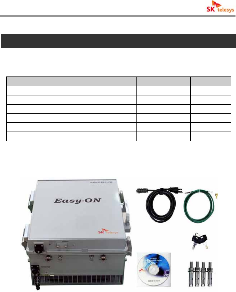
2. Components
2.1 Packing List
No Description quantity Remark
1 iDEN Repeater 1
2 AC Power Cable 1
3 Ground Cable 1
4 Bolts to fix the holder 4
5 Key 2
6 CD 1 Manual
<Table 1 > Packing List
< Fig. 2 > Components of iDEN Repeater
i-DEN REPEATER
SK Telesys Co., LTD Proprietary Document 10/46
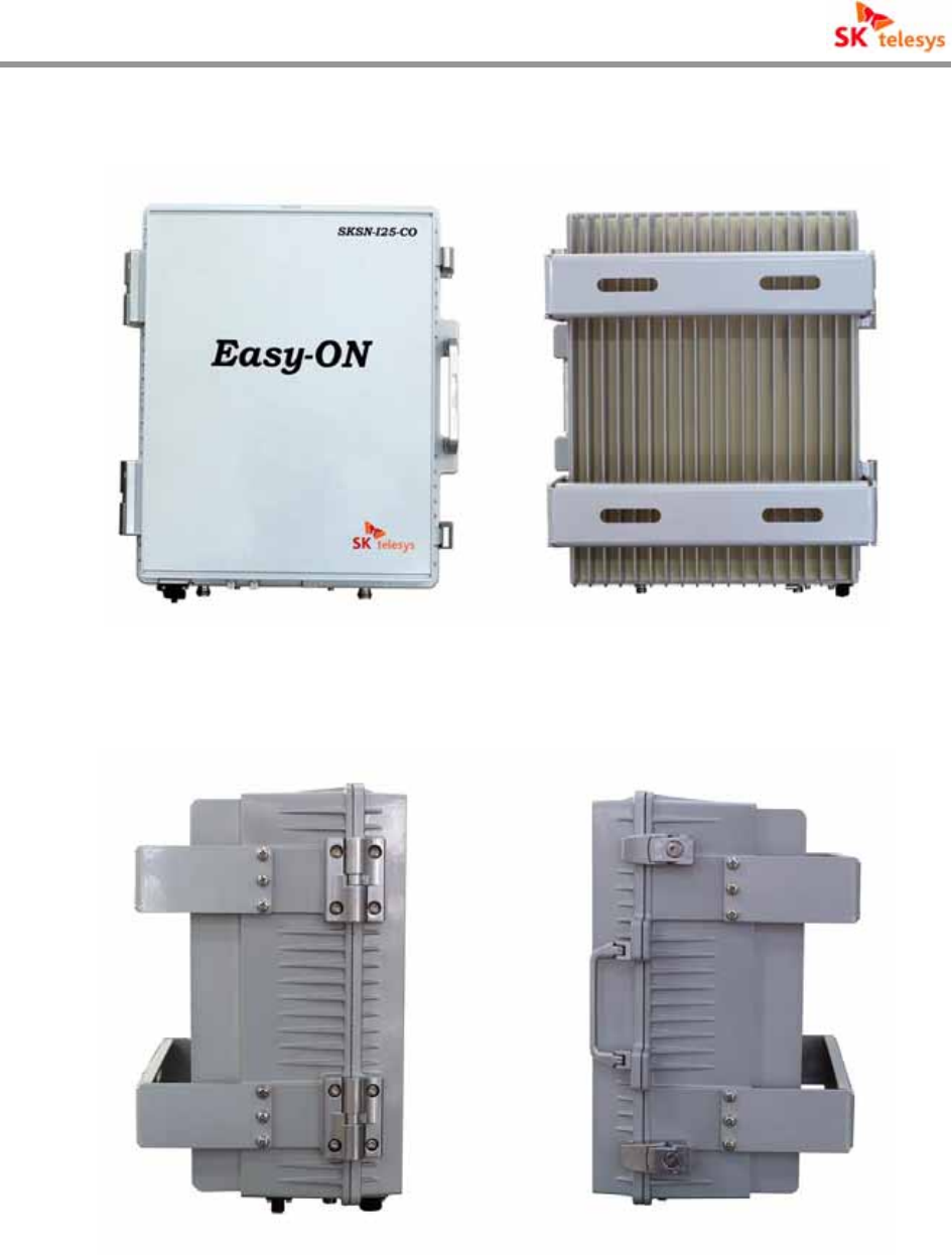
2.2 System Quick View
< Fig. 3 > Front & Back View of iDEN Repeater
< Fig. 4 > Side View of iDEN Repeater
i-DEN REPEATER
SK Telesys Co., LTD Proprietary Document 11/46
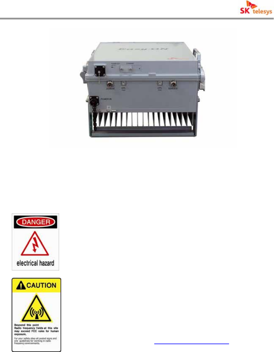
< Fig. 5 > Bottom View of iDEN Repeater
2.3 Warning and Hazards
WARNING!
ELECTRIC SHOCK
Danger of electric shock!
Switch off while( it is ) maintained and inspected!
WARNING! EXPOSURE TO RF
Working with the repeater while in operation, may expose the
technician to RF electromagnetic fields that exceed FCC rules for
human exposure.
Visit the FCC website at www.fcc.gov/oet/rfsafety to learn more
about the effects of exposure to RF electromagnetic fields.

i-DEN REPEATER
SK Telesys Co., LTD Proprietary Document 12/46
RF EXPOSURE & ANTENNA PLACEMENT
Actual separation distance is determined upon gain of antenna
used.
Please maintain a minimum safe distance of at least 20 cm while
operating near the donor and the service antennas. Also, the
donor antenna needs to be mounted outdoors on a permanent
structure.
Warning!
This equipment generates or uses radio frequency energy.
Changes or modifications to this equipment may cause harmful
interference unless the modifications are expressly approved in
the instruction manual. The user could lose the authority to
operate this equipment if an unauthorized change or modification
is made.
FCC STATEMENT
This equipment has been tested and found to comply with the
limits for a Class A digital device, pursuant to Part 15 of the FCC
Rules. These limits are designed to provide reasonable protection
against harmful interference when the equipment is operated in a
commercial environment. This equipment generates, uses, and
can radiate radio frequency energy and, if not installed and used
in accordance with the instruction manual, may cause harmful
interference to radio communications.
Operation of this equipment in a residential area is likely to cause
harmful interference in which case the user will be required to
correct the interference at
own expense.
i-DEN REPEATER
SK Telesys Co., LTD Proprietary Document 13/46
3. Features and Specification
3.1 Electrical Specification
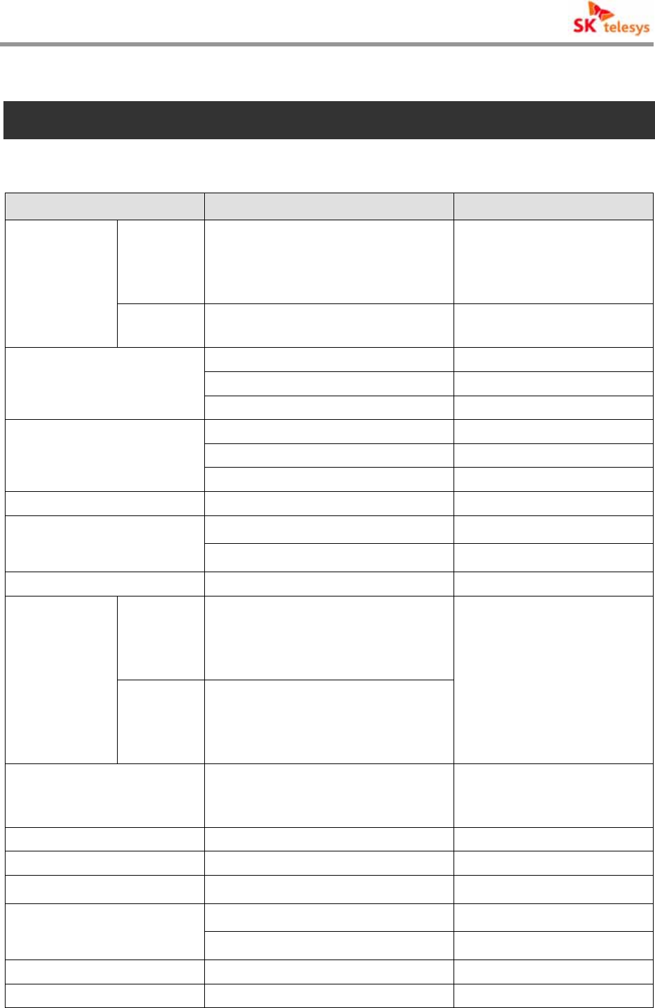
Item Specification Remark
800MHz
Downlink : 851~874MHz
(Ability to switch 862~869 MHz)
Uplink : 806~824MHz
(Ability to switch 817~824 MHz)
25kHz Step
Frequency
Range
900MHz Downlink : 935~940MHz
Uplink : 896~901MHz 25kHz Step
65dB / 15dBm iDEN(65/15)※
65dB / 25dBm iDEN(65/25)※
Amplifier Gain /
Output Power per Channel
80dB / 30dBm iDEN(80/30)※
-25 ~ -50dBm / Total iDEN(65/15)※
-15 ~ -40dBm / Total iDEN(65/25)※
Input Level
-20 ~ -50dBm / Total iDEN(80/30)※
Ripple 2.5 dB p-p
25 dB(1dB/Step±0.5dB or less) iDEN(65/15),(65/25)※
Gain Control Range
30 dB(1dB/Step±0.5dB or less iDEN(80/30)※
Roll offs Over ∆65dBc @Band Edge± 500 KHz
1 carrier
25KHz : 50dBc
50KHz : 55dBc
500KHz : 55dBc
1MHz, 2MHz : 55dBc
Downlink
Adjacent
Power
8carriers
25KHz : 47dBc
50KHz : 52dBc
500KHz : 52dBc
1MHz, 2MHz : 52dBc
Out of band paging
carrier rejection
929~932MHz(3MHz),
940~941MHz(1MHz)
Input : -15dBm ~ +5dBm
900MHz Inter modulation 1870~1880MHz/-105dBm 900MHz only
Spurious RF Emission -13dBm or less
Propagation Delay 8us or less
5dB or less @Gain 65dB(Uplink)
Noise Figure
12dB or less @Gain 40dB(Uplink)
VSWR 1.5 : 1
Input/output connector N-Type (Female)
i-DEN REPEATER
SK Telesys Co., LTD Proprietary Document 14/46
Input/output impedance 50Ω
Power 108 ~ 127 VAC, 60Hz Option ※-40 to -60VDC
20 to 30 VDC
<Table 2 > System Features
3.2 Mechanical Specification
Item Specification
Cabinet Indoor Type
RF Connector Type(IN/OUT) N-Type Female
390*326*190 mm iDEN(65/15)※
390*326*210 mm iDEN(65/25)※
Dimension
(H*W*D)
390*326*240 mm iDEN(80/30)※
18.5Kg iDEN(65/15)※
20.0Kg iDEN(65/25)※
Weight
21.5Kg iDEN(80/30)※
<Table 3 > Figure and Function
3.3 Environmental Specification
Item Specification Remark
Working temperature/
working humidity -10 ~ 50 / 5 % ~ 95%℃℃ Temperature and humidity
around cabinets
Power 108 ~ 127 VAC, 60Hz Option ※-40 to -60VDC
20 to 30 VDC
< Table 4 > Environmental specifications
i-DEN REPEATER
SK Telesys Co., LTD Proprietary Document 15/46
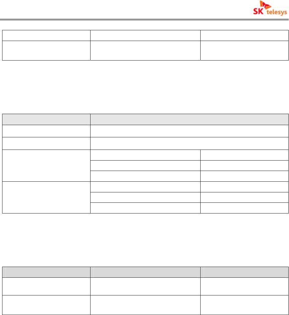
3.4 Operational Frequencies
Item Specification Remark
851 ~ 869 MHz 25kHz Step
800 MHz 862 ~ 869 MHz 25kHz Step
Down Link
900 MHz 935 ~ 940 MHz 25kHz Step
806 ~ 824 MHz 25kHz Step
800 MHz 817 ~ 824 MHz 25kHz Step
Up Link
900 MHz 896 ~ 901 MHz 25kHz Step
< Table 5 > iDEN Frequency
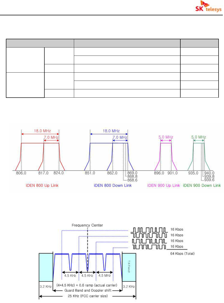
< Fig. 6 > iDEN Frequency
< Fig. 7 > Features of iDEN Carrier
i-DEN REPEATER
SK Telesys Co., LTD Proprietary Document 16/46
4. System Block Diagram
4.1 Block Diagram
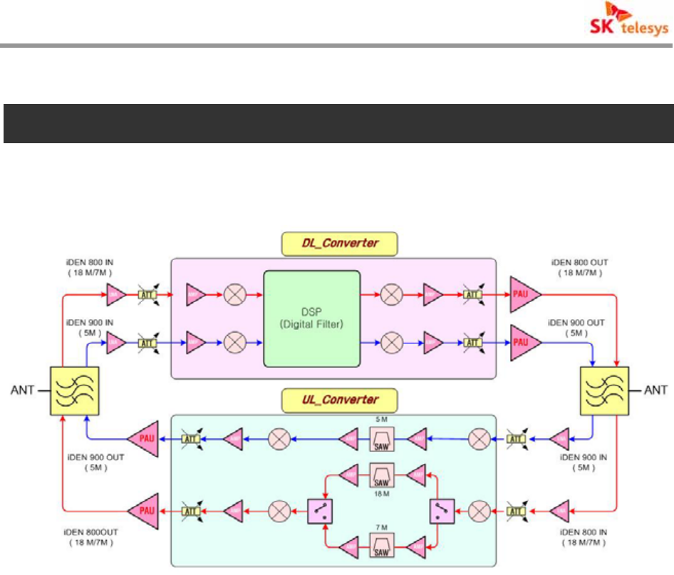
< Fig. 8 > Block Diagram
4.2 Block Diagram description
A cavity type of filter is linked with Donor ANT and Service ANT of iDEN repeater, which
selectively passes the operating spectrum bandwidth between the received EBTS signal and
terminal signal.
Up/Down Converter Module consists of Down converter, Up converter and Digital Filter of
variable bandwidth from Filter to PAU input between Down link and Up link of iDEN repeater.
And to handle two bandwidths of 900 MHz and 800MHz the same paired structure is deployed.
Up/Down Converter of Down Link converts EBTS signal input through LNA part to IF
frequency(62.5MHz), which feeds into A/D conversion to send it to Digital Filter..
Digital filter is deployed to achieve excellent roll off characteristics ,minimize the impact of other
signal by notching adjacent bandwidths and other interfering signal, removes spurious and
improves degree of signal separation.
In addition, Up link unlike Down link converts Terminal’s RF signal input through LNA to IF

i-DEN REPEATER
SK Telesys Co., LTD Proprietary Document 17/46
frequency(70MHz) to take roll off nature equivalent to that of SAW Filter, minimizes the impact
of other signals by suppressing the adjacent signals to remove spurious and to improve degree
of separation.
PAU amplifies iDEN signal at proper output level with the module at the final end to pass
through Multiplexer to emit via antenna.
i-DEN REPEATER
SK Telesys Co., LTD Proprietary Document 18/46
5. System Overview
5.1 Configuration and Features of System
Modules comprising iDEN (Integrated Digital Enhanced Network) Repeater is arranged for
operators and technicians to utilize them effectively.
iDEN RF Repeater’s basic structure is wall mount, and if required it is constructed to be installed
on 19 inch Rack. And the grounding terminal is attached to the bottom of the repeater..
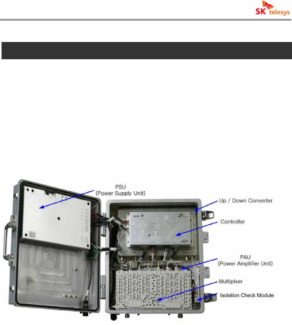
iDEN RF repeater consists of PSU(Power Supply Unit), Controller, Up / Down Converter,
PAU(Power Amplifier Unit), Multiplexer and Isolation Check.
< Fig. 9 > Internal Construction of iDEN Repeater
i-DEN REPEATER
SK Telesys Co., LTD Proprietary Document 19/46
한글
지울 것
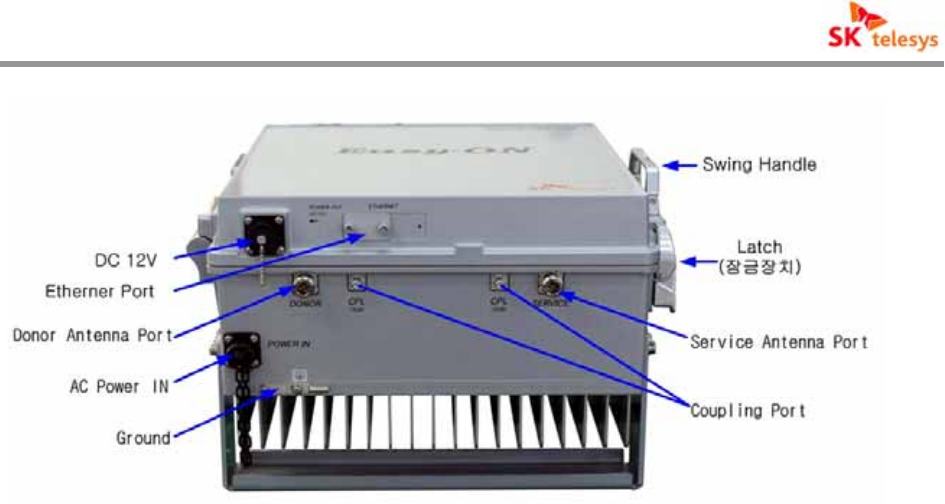
< Fig. 10 > Bottom View of iDEN RF Repeater
5.1.1 PSU (Power Supply Unit)
AC power source is converted through A/D and D/D to feed stable current to each devices
having active elements, which adopts industrial equivalent or above level of parts. It is highly
robust physical structure and satisfies all required electrical specification.
Operating power ranges from AC 108- to 127V input and it converts to DC 3.8V, DC 7V, DC 12V
and DC 27V for use.
5.1.2 Controller
The controller consists of RCB(RF Control Board) and NCB(Network Control Board) to monitor
and control the state of each module of iDEN repeater.
RCB(RF Control Board) is linked to GUI through DEBUG port to collect status information and
control modules.ller.
NCB(Network Control Board) enables high-level NMS(Ethernet) communication through RJ-45
port to monitor and control the state. It has LED to display the state in the front panel of NCB’ to
easily identify any malfunction of Module.
Since the controller is run by exchangeable batteries, when exchanged in a wrong form, it may
explode and used batteries must be safely disposed.
※Caution
i-DEN REPEATER
SK Telesys Co., LTD Proprietary Document 20/46
Improper replacement of batteries can bring about risk of explosion.
Dispose of used batteries according to manufacturer’s instructions.
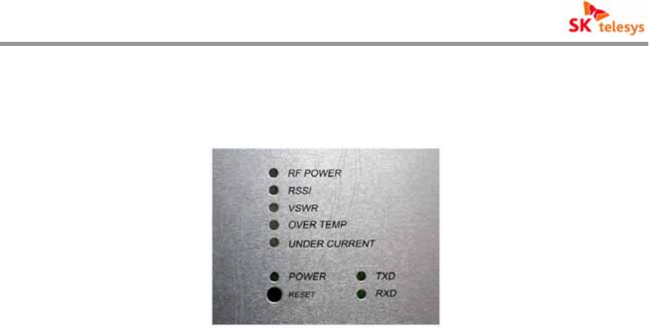
(1) LED
a. RF POWER : On alarming Red light, On normal running Green LED
b. RSSI : On alarming Red light, On normal running Green LED
c. VSWR : On alarming Red light, On normal running Green LED
d. OVER TEMP : On alarming Red light, On normal running Green LED
e. UNDER CURRENT : On alarming Red light, On normal running Green LED
f. POWER : On power admitted Green light, On normal communication
Green blinking.
h. RESET : Controller Reset Button
i. TXD : On Data transmitting with Web GUI connected Green blinking
j. RXD : On Data receiving with Web GUI connected Green blinking
5.1.3 Up / Down Converter
Up/Down Converter consists of Down converter, Up converter and Digital Filter of variable
bandwidth from Filter to PAU input between Down link and Up link of iDEN repeater. And to
handle two bands of 900M band and 800M band a paired structure is applied.
Up/Down Converter of Down Link converts EBTS signal input through LNA part to IF
frequency(62.5MHz), which feeds into A/D conversion to send it to Digital Filter..
Digital filter is deployed to achieve excellent roll off characteristics ,minimize the impact of other
signal by notching adjacent bandwidths and other interfering signal, removes spurious and
improves degree of signal separation.
In addition, Up link unlike Down link converts Terminal’s RF signal input through LNA to IF
frequency(70MHz) to take roll off nature equivalent to that of SAW Filter, minimizes the impact
of other signals by suppressing the adjacent signals to remove spurious and to improve degree

i-DEN REPEATER
SK Telesys Co., LTD Proprietary Document 21/46
of separation.
Insertion of band passing filter in front end of Mixer restrains local signal from leaking into Input
stage. Mixer adopts parts with the feature of high IP3 to minimize IMD component of system,
maintain linearity to minimize impact on the next stage. EBTS signal changed into IF
frequency is to be recovered into the original frequency through Up Converter.
Local step for IF conversion is designed to minimize phase noises in order not to reduce
quality(ρ value) of waveform that can take place during the conversion process of signals.
RF Block of Down Link Up/Down Converter as Down Link Gain Control Block phase performs
AGC and ALC functions to protect devices on over-input of iDEN RF Repeater, and the user
may turn On/Off the functions with automatic compensation function for gains depending on the
temperature variation of the system.
5.1.4 Multiplexer
A cavity type of filter is linked to Donor ANT of iDEN Repeater, which selectively passes the
operating bandwidths among signals of EBTS received from antenna whereas other bandwidths
are rejected for the operating bandwidth to be served. which only can be input into LNA end
after achieving enough Isolation between Down Link and Up Link. And Up Link operates to
minimize Spurious power occurred in PAU.
5.1.5 PAU(Power Amplifier Unit)
PAU deploys parts with reliability and durability of higher P1dB value considering spurious
characteristics. It monitors output levels at all times by linking to control part. So when main
problem happens, it reports to upper level and if required by the user PAU can be switched
On/Off.
Down Link PAU amplifies iDEN signal to proper output level and supply controller with VSWR
information of output port and output level.
Also it detects its own operating temperature and supply controller with information on device
failure to check normal operation state of module.
5.1.6 Cabinet
Cabinet of Repeater has die-casting structure enabling modules to be installed inside of door
panel to enhance implementation efficiency and minimize the size of cabinet.
i-DEN REPEATER
SK Telesys Co., LTD Proprietary Document 22/46
Heat fin size of repeater is calculated upon the output level to show an excellent heat dissipation
effect .
(1) Latch
Latch is well sealed and locked to secure safety in which it can play a major role in
preventing moisture and vibration.
With automatic lift function of Head, door can be easily opened and closed. Minimized gap
of shafts of Latch prevents shaking.
Strengthening Shaft hardness and recess Automatic lift function of Head
< Fig. 11 > Latch Structure
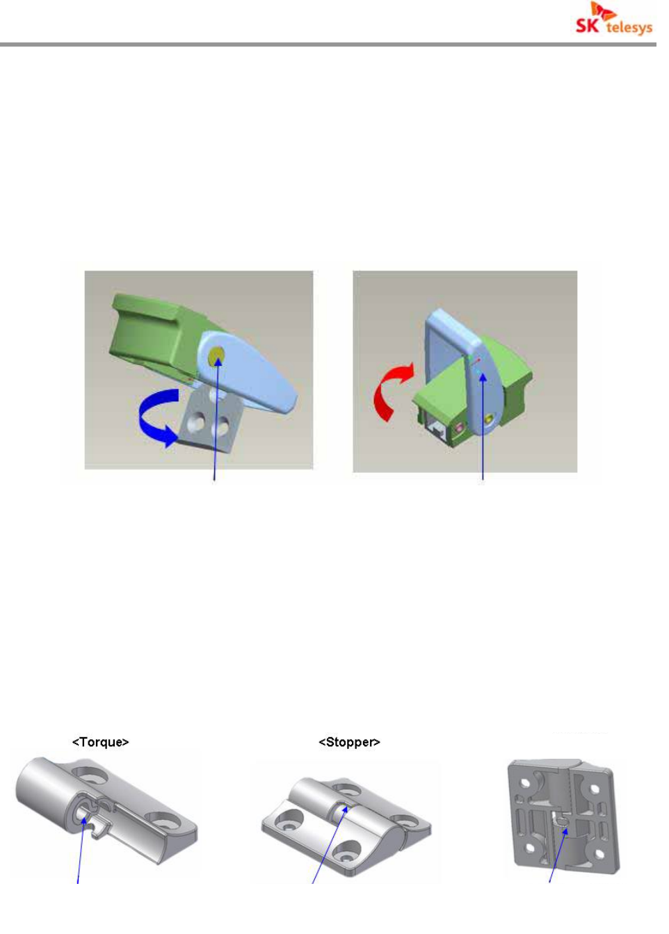
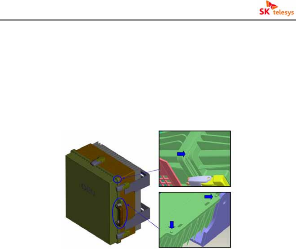
(2) Hinge
On assembling and maintaining cabinet it is designed to consider convenience and rapidity
for its opening and closing, and it has 3 merits such as Torque, Stopper and Separation
Angle function.
< Separated angle>
Torque function realization A stopper function when
opening cabinets Separation when opening
cabinets
i-DEN REPEATER
SK Telesys Co., LTD Proprietary Document 23/46
< Fig. 12 > Hinge Functions
A. Torque Function
It prevents sudden door opening or closing considering the operator’s safety when
assembling and operating.
B. Stopper Function
It keeps sudden door opening from damaging cabinet on maintaining after
assembling and set up. The additional design for opening has double safety structure
for stopping function.
C. Separation Angle Function
Attached Notch to the center bottom of Hinge keeps separation on closing, and as
opening in a certain angle(about 20-30 degree) Door and Body part of Cabinet may
be separated.
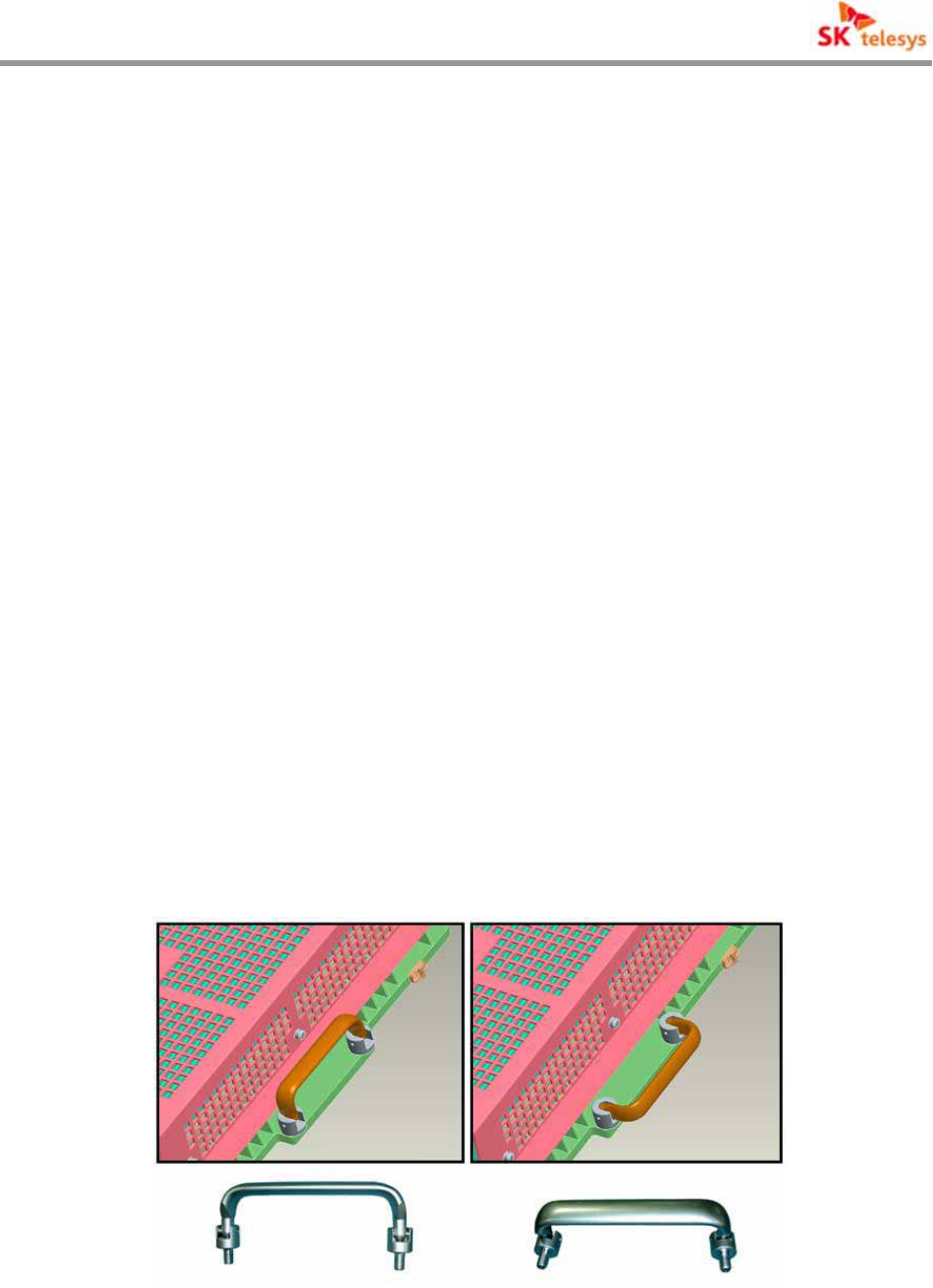
(3) Swing Handle
On carrying the cabinet a folding type of Handle is designed for safety and convenience,
and it has a fine view because it can be folded inward.
When Door of Cabinet is open, closed or moved, it is convenient to be reversely lifted for
use. A rigid material for Handle is applied for delivery safety considering the weight of
equipment.
< Fig. 13 > Swing Handle Function
(4) Wrench Prevention Sill
i-DEN REPEATER
SK Telesys Co., LTD Proprietary Document 24/46
It is put on Door part, which prevents cabinet of repeater from wrenching because of
vibration and external environment after set up.
(5) Guide
To keep from wrenching between cabinets after assembling it has Guide function. At the
same time contact area extension of Door and Body part of Cabinet enhances heat
transmission effect.
< Fig. 14 > Guide for Wrench Prevention
5.2 Additional Functions
5.2.1 ALC Function
The function is for stable operation of repeater and base station to keep output of repeater from
exceeding pre set limit.
A. Procedure
a. Switch ON/OFF ALC function set up through GUI.
b. When Down Link output value is more than set up level or less than 1dB, correct
the difference.
c. When Up Link output value is more than set up level or less than iDEN 1dB,
correct the difference.
d. Monitor output value of Down Link and Up Link every second.
B. Notes
a. Down Link and Up link operates independently.

i-DEN REPEATER
SK Telesys Co., LTD Proprietary Document 25/46
b. On oscillation check mode, it does not operate.
5.2.2 Shutdown Function
When output of repeater exceeds set up limit, it is to function Shutdown for stable protection.
A. Procedure.
a. Operate when output value of Down Link and Up Link is 3dB(iDEN Shutdown
Level) over ALC set up limit.
b. Monitor output for 5 seconds to find that 5 second output is operational
condition. Then do PAU OFF to perform the first Shutdown.
c. Perform PAU ON for 5 seconds after Shutdown.
d. Monitor output for 4 seconds again after waiting for stable output for 1 second.
e. Perform c, d and e 3 times.
f. After 3rd PAU ON standby time is 30 minutes. With Shutdown condition
afterward, perform complete Shutdown state.
g. On complete Shutdown state the user should directly switch the repeater OFF
or ON, or set up PAU ON to recover from the complete Shutdown state.
B. Notes
a. Do not operate when ALC Operation set up is OFF.
b. Down Link and Up Link operate independently.
5.2.3 Oscillation Check Function
A. Procedure
a. Switch ON/OFF oscillation check function with GUI.
b. Check 798 ~ 799MHz range through channel scan.
c. Change frequency up to 798 ~ 799MHz by 30KHz to measure oscillation detect
value.
d. Find the minimum and maximum value from values measured from c.
B. Notes
a. Do not operate while channel scan is in operation.
b. When ALC is operating, gain correction value should not exceed ALC set up
level.
c. When Up Link ALC operation is OFF, link Down Link Gain to operate.

i-DEN REPEATER
SK Telesys Co., LTD Proprietary Document 26/46
5.2.4 Oscillation Shutdown Function
A. Procedure
a. Operate when oscillation attenuation is over 30dB.
b. Switch all PAU OFF and start alarming.
c. Return PAU to original state after 10 seconds to perform oscillation check
function.
d. On continuous Shutdown condition, try 3 times to enter complete Shutdown
state afterward.
e. On complete Shutdown state the user should directly switch the repeater OFF
or ON, or set up PAU ON to come out of complete Shutdown state.
B. Notes
a. Operate when oscillation check function is ON only.
i-DEN REPEATER
SK Telesys Co., LTD Proprietary Document 27/46
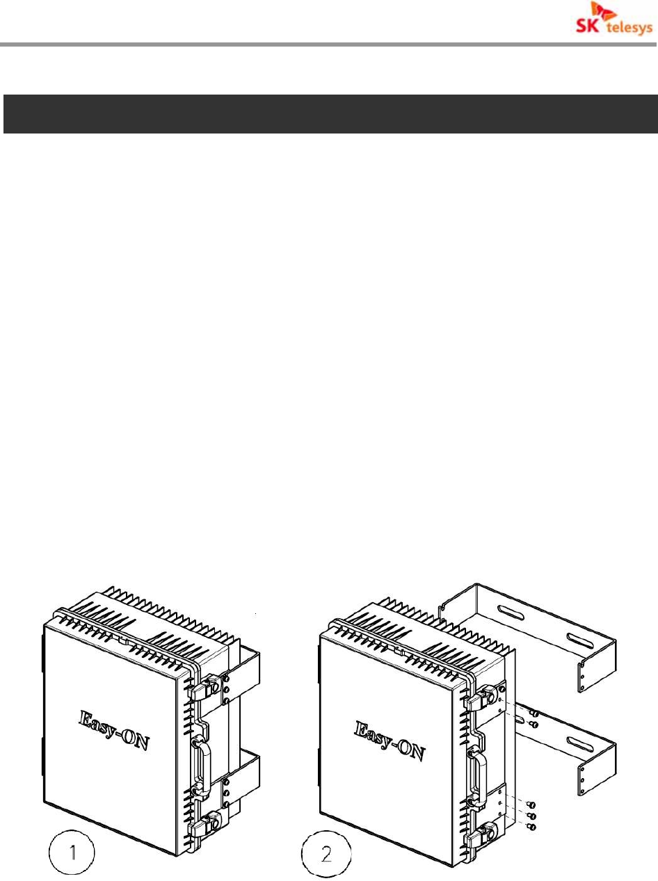
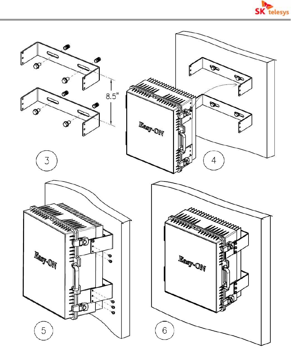
6. System Installation guide
Cabinet of Repeater is die-casting structure, in which it basically supports wall-mount installation
and if required it can be installed at 19 inch Rack.
Holder of Repeater has 4 Wall Mount Holes, which needs to be installed safely enough to
sustain the weight of repeater on wall-mount installation.
The procedure for wall-mount installation is as follows;
(1) Take Repeater out of package.
(2) Check the components of repeater to remove 12 screws assembled to bracket from
the repeater.(6 per side).
(3) Use 4 anchor bolts to fix bracket to the wall.
(4) Check if bracket is safely installed to the wall.
(5) Wall-mount Bracket has 2 Guard screws. Lightly attach the repeater to 2 Guard
screws then fix the other screw safely.
(6) Check if it is installed safely and firmly.
i-DEN REPEATER
SK Telesys Co., LTD Proprietary Document 28/46
< Fig. 15 > Mounting Sequence of the iDEN Repeater
i-DEN REPEATER
SK Telesys Co., LTD Proprietary Document 29/46
7. Web GUI Installation guide
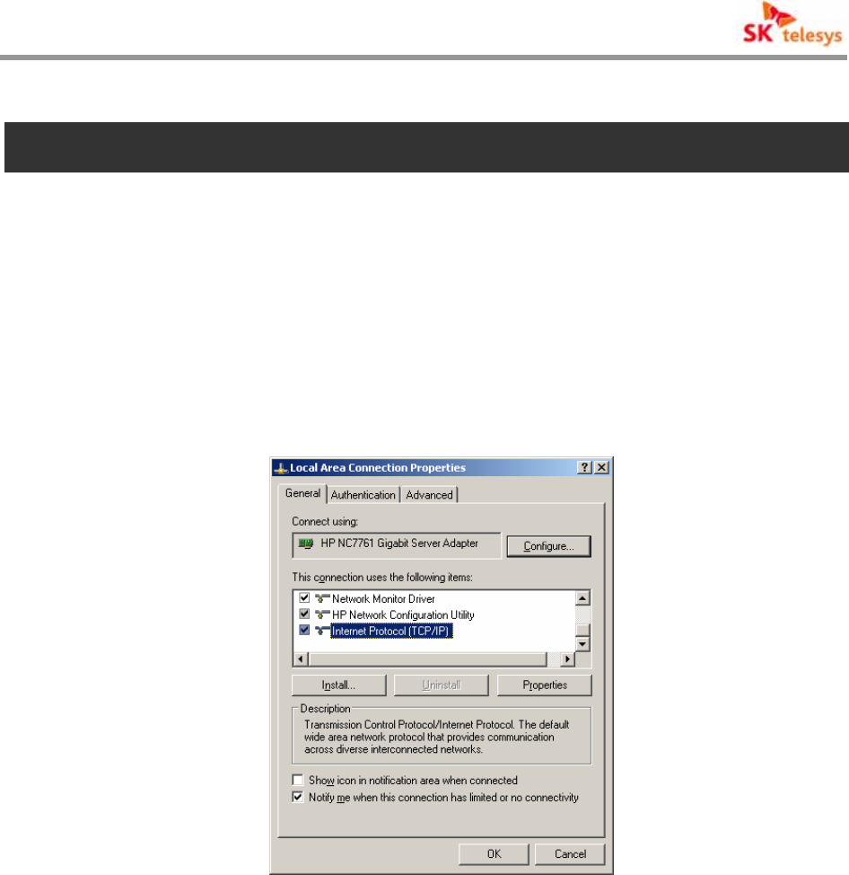
7.1 Program Setup
(1) The Ethernet Ports of Repeater and Laptop are linked through LAN Cable.
(2) Cross Cable is used for LAN Cable.
(3) When selecting the following picture, IP is automatically assigned to Laptop computer
from the repeater.
< Fig. 16 > Local Area Connection Properties
i-DEN REPEATER
SK Telesys Co., LTD Proprietary Document 30/46
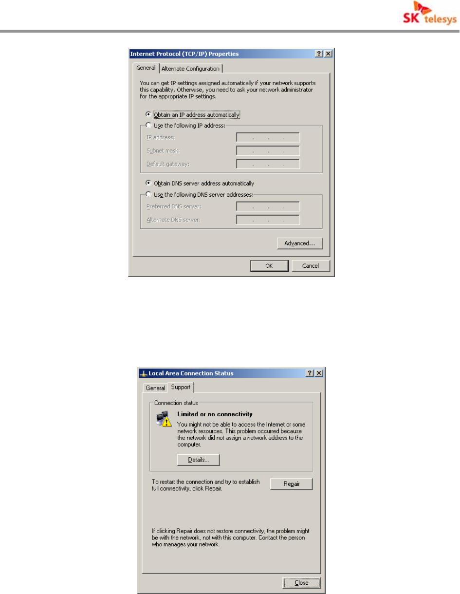
< Fig. 17 > Internet Protocol(TCP/IP) Properties
(4) When network is not linked in a certain time, select Repair on Support window to
recover IP.
< Fig. 18 > Local Area Connection State-1
i-DEN REPEATER
SK Telesys Co., LTD Proprietary Document 31/46
< Fig. 19 > Local Area Connection State-2
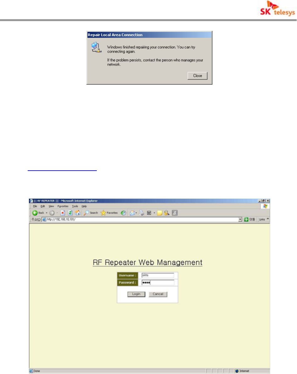
7.2 Web GUI Connection
(1) Input connection address on address window of Internet Explorer to access.
(2) The Connection address set up as the repeater is released is as follows;
http://192.168.10.101/
When linked to the repeater, input Username and Password on Login screen as
follows to click [Login].
< Fig. 20 > Web GUI Initial Screen
(3) Default Username & Password set up as the repeater is released are skts & skts .
(4) As linked to Web GUI, the following screen appears.
i-DEN REPEATER
SK Telesys Co., LTD Proprietary Document 32/46
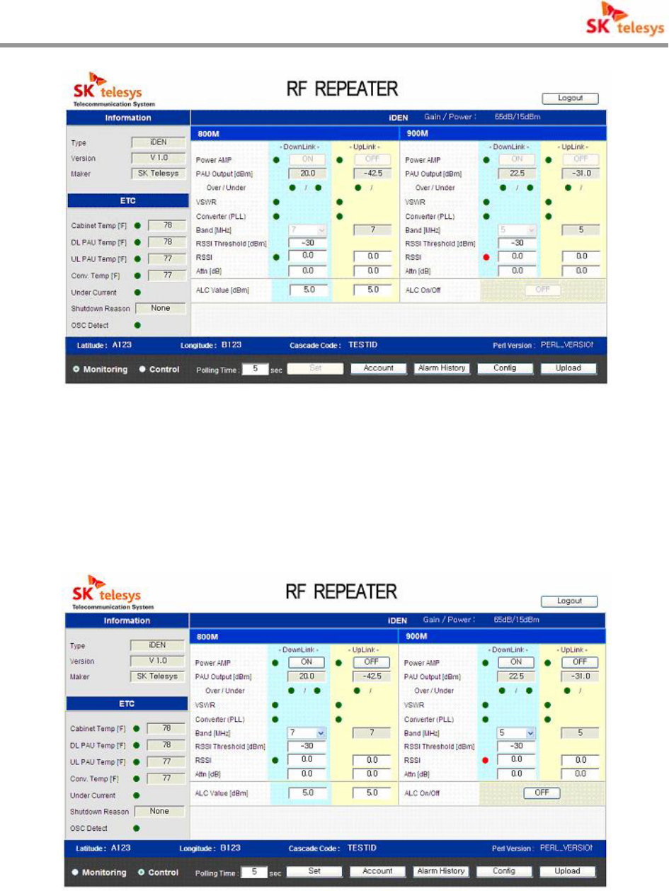
< Fig. 21 > Monitoring Screen of iDEN Repeater State
(5) After connected, read the state from repeater system and updates on screen.
(6) When selecting Control at bottom of connection screen, it stops Polling and activates
Set Button and controllable items to change into control mode to alter set up value.
< Fig. 22 > Control Screen of iDEN Repeater State
i-DEN REPEATER
SK Telesys Co., LTD Proprietary Document 33/46
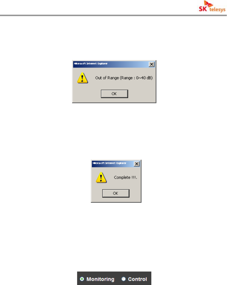
(7) On changing set up value when the input range set by items is exceeded, warning
window appears to return to the earlier value.
< Fig. 23 > Input Range Excess Message
(8) After changing set up value, press Set button to transmit the changed data. When set
up is completed, the message appears.
< Fig. 24 > Set Up Completion Message
7.3 Monitor/Control of Web GUI State
When you can select Mode Select at bottom of main screen of Web GUI, it follows, monitors
and controls the operation repeater.
< Fig. 25> Mode Select
(1) When selecting Monitoring Mode, it monitors the present state of repeater system.
(2) When selection Control Mode, it stops Updating of repeater system and changes into
controllable Mode.
(3) The basic Mode after connecting is Monitoring Mode, and after controlling repeater on
i-DEN REPEATER
SK Telesys Co., LTD Proprietary Document 34/46
Control Mode it automatically changes into Monitoring Mode.
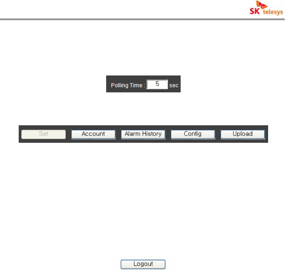
As for Monitoring Mode it is Polling period to update the state from system. It may input
between minimum 5 up to 60 seconds.
< Fig. 25 > Polling Time
< Fig. 26 > Function Button
Set : It activates on Control Mode. After changing set up value take down the control
on system to change state.
Account : Manages User’s information.
Alarm History : May show Alarm History Data on system.
Config : Reads and changes the parameter value affecting system connection.
Upload : Upload system program.
< Fig. 27 > Logout
Ends the present connection.
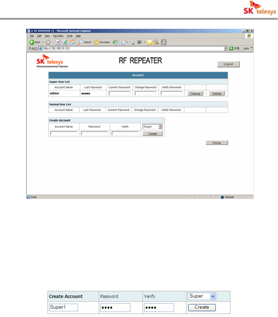
7.3.1 Account
It can register or delete the users accessible to Use Management page, and the grade of user is
divided into Super user and Normal user.
Total maximum number of users available for registration is 4 for super user and 25 for normal
user.
On shipment the Default Super User name & Password of repeater are skts & skts .
As pressing Home button it returns to the main screen.
i-DEN REPEATER
SK Telesys Co., LTD Proprietary Document 35/46
< Fig. 28 > Account Page
7.3.2 User Registration
Select the right of User to register on Create Account Block at the bottom of Page, input User
Name and Password to be registered as new and press Create Button to register.
< Fig. 29 > User Registration
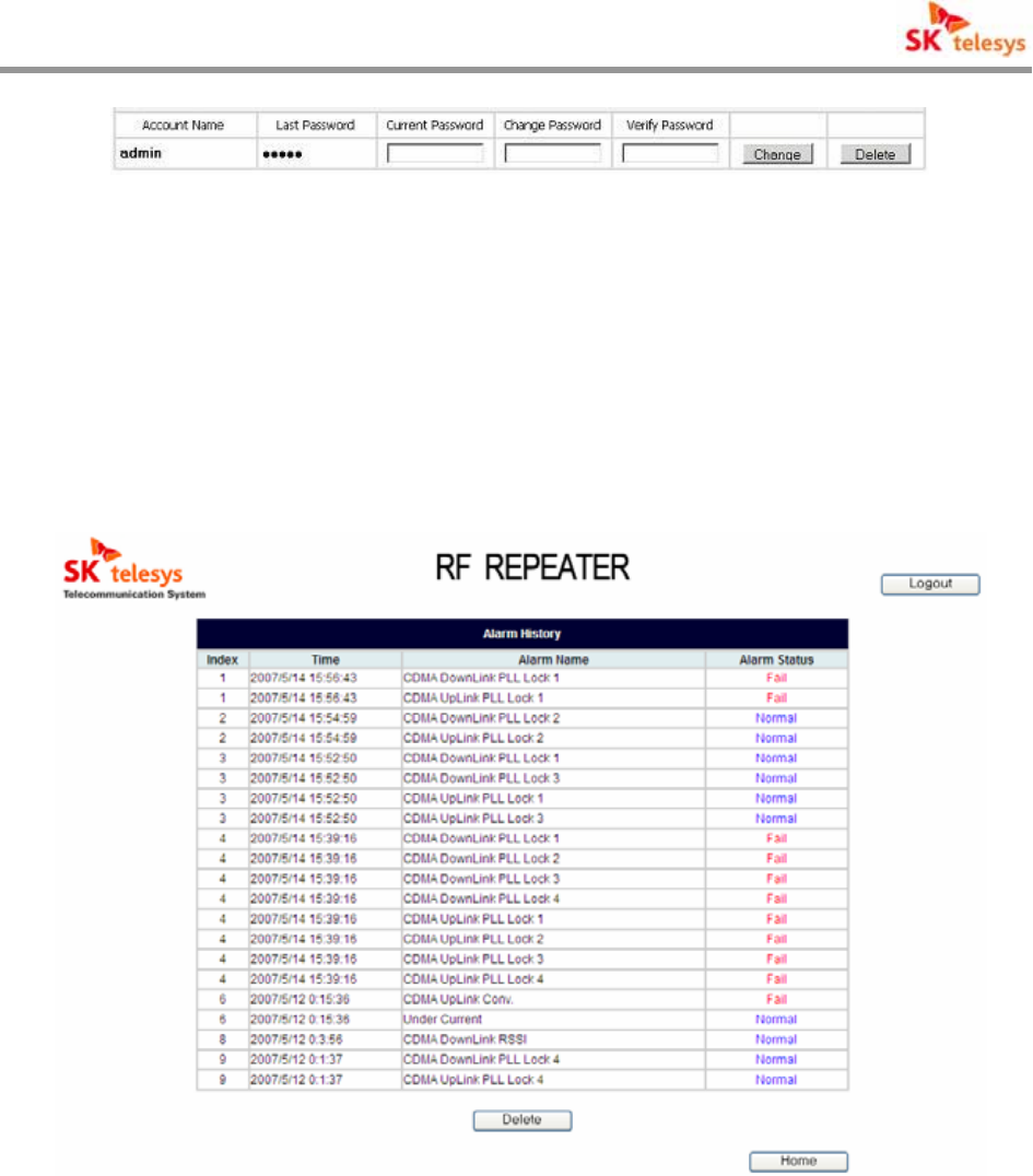
7.3.3 Delete and Change of User
Delete of User is Super User’s unique right. Press Delete button on the right of User List Block
to delete. Delete of Super User Name is possible only with input of Current Password. Delete of
Normal User is just available by pressing Delete button.
To change Password press Change button to apply after new Password input.
i-DEN REPEATER
SK Telesys Co., LTD Proprietary Document 36/46
< Fig. 30 > Deletion and Change of User
7.3.4 Alarm History
Alarm details stored in system can be seen, which shows the occurrence time of alarm, its
occurrence and release.
Alarm History can be seen up to Index 50.
< Fig. 31 > Alarm History
Press Delete button at the bottom to delete alarm details stored, and the deleted alarm details
can not be restored.
Press Home button to return to main screen.
i-DEN REPEATER
SK Telesys Co., LTD Proprietary Document 37/46
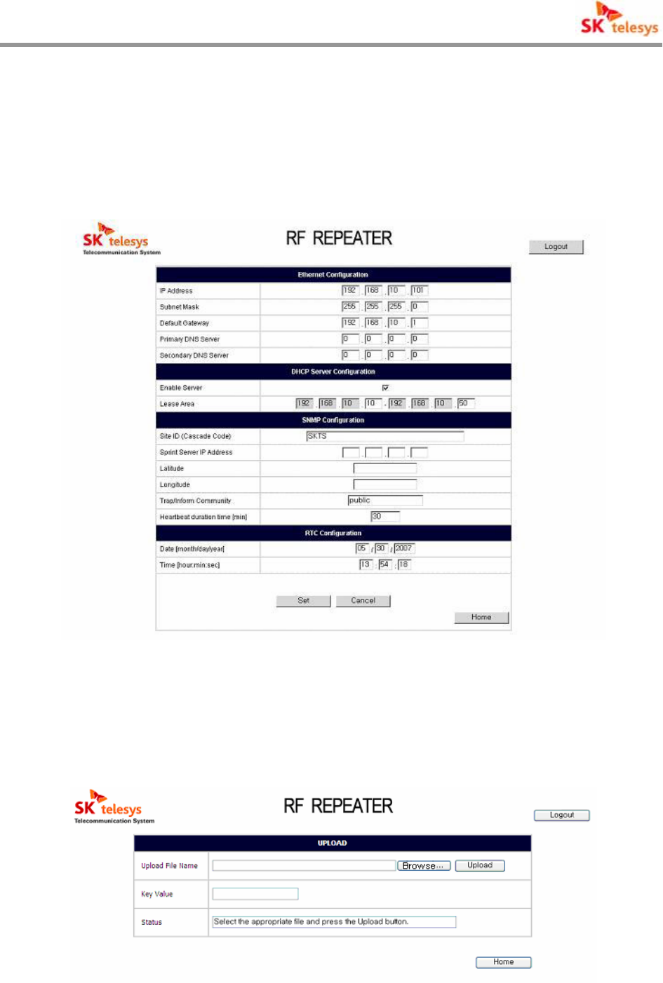
7.3.5 Config
It shows basic connection information required to connection and system configuration, and the
initial set up value on shipment is as follows;
< Fig. 32 > Construction Information of System
7.3.6 Up Load
Upload Page is necessary to Upgrade the system program.
< Fig. 33 > Upload Page
i-DEN REPEATER
SK Telesys Co., LTD Proprietary Document 38/46
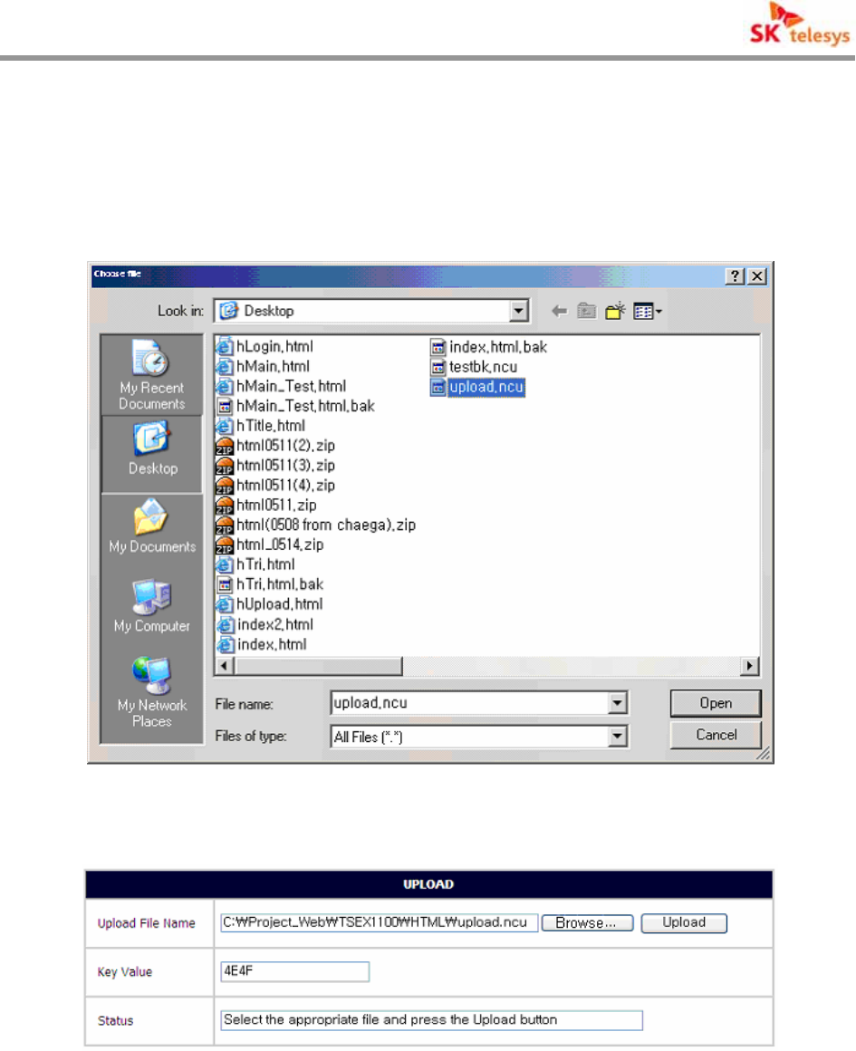
Click [Search] button to select the file for Uploading on Popup window.
Controller of repeater comprises Network Control Board and Repeater Control Board, and each
Board’s Upload file is divided into SKTSNCB_vxx.ncu and SKTSRCB_x_vx.x.xx.rcu.
< Fig. 34 > File Selection
< Fig. 35 >Upload Arrangement
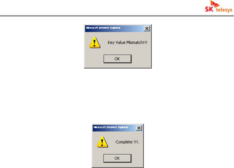
As the selected file path is seen, input Key Value provided and press Upload button to Upgrade
system.
If Key Value is different by files and inaccurate, Upload is impossible.
i-DEN REPEATER
SK Telesys Co., LTD Proprietary Document 39/46
< Fig. 36 > Key Value Error
On completion of Upload, the following message appears and system is automatically rebooted.
On rebutting connection is not available, after rebooted normal connection is available.
< Fig. 37 > Upload Completion

i-DEN REPEATER
SK Telesys Co., LTD Proprietary Document 40/46
8. Maintenance Guide
8.1 Confirmation of System Components
For normal operation of equipment the following should be confirmed on installation.
A. Confirm whether the repeater’s exterior would be deformed by damaged package
of repeater on delivery.
B. Confirm that the components of equipment as in the packing list and that the
location for installation satisfies temperature and humidity for operation of
equipment defined in the product specification.
C. Confirm the input signal condition of equipment defined in the product specification.
D. Confirm that the state of cable and connector is good.
E. Confirm that the state of bracket of repeater is good.
8.2 Cautions on System Installation
In order for dangerous events not to occur on installation of repeater, the provided guidance
should be followed.
Especially, the power cord of this repeater is of an eternal connection type, so an easily
accessible power interruption device should be installed in the indoor wiring, and there should
be an easily accessible socket-outlet near the repeater.
Order Description Cautions
1
Donor ANT welding and
feeder installation.
Service ANT or LCX equipped
• Cable should be installed without exterior damage.
• Protect connection parts like connector with insulation tape to
prevent humidity.
• Install feeder to minimize environment influence.
2 Installation of Antenna for
Donor
• Strongly fixed for local wind velocity to prevent antenna’s
direction from bending after installation
3 Power cable and RF cable
arrangement • Prevent cable from damaging by crooking or stretching.

i-DEN REPEATER
SK Telesys Co., LTD Proprietary Document 41/46
9. System Set Up and Inspection
9.1 Items to be checked for Opening
A. Confirm AC 108 ~ 127 VAC common use power and power cable.
B. Check if Donor RF input signal from exterior is at normal level.
※Caution
When system operates without input signal confirmed, over-input may cause serious
damage on amplifying devices because of saturation of output. Therefore, after checking
input signal level by equipment and ALC ON state(on shipment ALC ON), operate
equipment.
C. Put 108 ~ 127 VAC into power connector of equipment to switch ON.
D. Check Alarm LED blinking state of GUI or Repeater’s front board through lap top.
E. When it is judged that Down Link RF input signal from exterior is normal, switch
OFF the Repeater to connect ANT feed and Service ANT to Input/Output Port of
Repeater and switch ON again.
※Caution
Conclude carefully lest Down Link and Up Link Port be reversed.
9.2 Items to be check after opening
A. Check Alarm LED blinking of repeater to confirm abnormality.
B. Confirm RF input/output value’s normality with GUI.
C. About 10 minutes after switching ON the repeater measure Down Link and Up Link
Output Spurious feature of repeater by using spectrum analyzer of Coupling
terminal to confirm normality of operation.
D. After normal operation of repeater measure calling quality of service area by
terminal or measurer to optimize wave environment to see if wave shade area or
calling inability area is present comparing to the before opening condition.

i-DEN REPEATER
SK Telesys Co., LTD Proprietary Document 42/46
9.3 Failure and Inspection
9.3.1 Inspection of Repeater
On routine or emergency service of repeater the following orders should be taken to check its
failure.
A. Check RF input/output level and LED of repeater using Web GUI. On routine
service check calling quality with terminal or measurement equipment, or on
emergency service the following should be taken even if RF input/out level of
repeater on Web GUI is normal.
B. Connect link spectrum analyzer to test terminal of repeater to confirm output state.
C. Use Coupling port to check output value.
D. Check if the output value of repeater obtained by harmonic analyzer conforms to
actual out put value of repeater.
E. Check input level of repeater when the output value of repeater obtained by
spectrum analyzer does not conforms to actual output value of repeater.
F. When input level is not the same as the one on installation time showing distinct
difference, check antenna connection points and feeder installation state.
G. If the output value of repeater is abnormal as comparing input level to operation
gains of repeater, switch ON/OFF the repeater to check the output state with
spectrum analyzer. On severe failure immediately replace with spare parts to
recover to the normal service.

i-DEN REPEATER
SK Telesys Co., LTD Proprietary Document 43/46
9.3.2 Facility Inspection
On routine Inspection and service failure the following parts and items are needed to be
inspected.
Inspection Parts Inspection Items Remark
Donor Antenna & Service
Antenna
Inspect the malfunction of Antenna’s welding,
received signal’s intensity of donor antenna
and RSSI value.
Feeder, Leakage Coaxial
Cable
Inspect whether feeder or leakage coaxial
cable may be cut or damaged.
Connector, Distributor
Inspect whether connector’s linking part or
cable may be flooded, or whether each linking
part is firmly fastened.
Power Incoming Part Confirm that common terminal box for 108 ~
127 VAC is not leaked.

i-DEN REPEATER
SK Telesys Co., LTD Proprietary Document 44/46
10 . Warranty and Repair Policy
10.1 General Warranty
This product carries a Standard Warranty period of five (5) years unless indicated otherwise on
the package or in the acknowledgment of the purchase order.
10.2 Limitations of Warranty
Your exclusive remedy for any defective product is limited to the repair or replacement of the
defective product. SK Telesys Corp. may elect which remedy or combination of remedies to
provide in its sole discretion. SK Telesys Corp. shall have a reasonable time after determining
that a defective product exists to repair or replace the problem unit. SK Telesys Corp. warranty
applies to repaired or replaced products for the balance of the applicable period of the original
warranty or ninety days from the date of shipment of a repaired or replaced product, whichever
is longer.
10.3 Limitation of Damages
The liability for any defective product shall in no event exceed the purchase price for the
defective product.
10.4 No Consequential Damages
SK Telesys Corp. has no liability for general, consequential, incidental or special damages.
10.5 Additional Limitation on Warranty
SK Telesys Corp. standard warranty does not cover products which have been received
improperly packaged, altered, or physically damaged. For example, broken warranty seal, labels
exhibiting tampering, physically abused SK Telesys Corp. Proprietary Document Page 27 of 31
iDEN RF Repeater User Manual enclosure, broken pins on connectors, any modifications made
without SK Telesys Corp. authorization, will void all warranty.

i-DEN REPEATER
SK Telesys Co., LTD Proprietary Document 45/46
10.6 Return Material Authorization (RMA)
No product may be returned directly to SK Telesys Corp. without first getting an approval from
SK Telesys Corp. If it is determined that the product may be defective, you will be given an RMA
number and instructions in how to return the product. An unauthorized return, i.e., one for which
an RMA number has not been issued, will be returned to you at your expense. Authorized
returns are to be shipped to the address on the RMA in an approved shipping container. You will
be given our courier information. It is suggested that the original box and packaging materials
should be kept if an occasion arises where a defective product needs to be shipped back to SK
Telesys Corp. To request an RMA, please call 1-888-758-7002 or send an email to
service@sktelesys.com.
i-DEN REPEATER
SK Telesys Co., LTD Proprietary Document 46/46
☎ Contact Information
Maker
Korea Office
Address
SK Telesys Co., Ltd
12-13F, Naewei Bldg.6, Eulgiro-2Ga, Jung-Gu, Seoul 100-844, Korea
Homepage: www.sktelesys.com
US Office
Address SK Telesys Corp.
12750 center court drive suite #400, Cerritos, CA 90703
Staff in charge
of sales
Kap Soo, Park, Director
Phone: 1-562-207-1924, Fax: 1-562-207-1925
Email: kapspark@sktelesys.com
Service contact
in US Email : service@sktelesys.com
Phone: 1-888-758-7002