SK Telesys SKSN-I30-CO iDEN RF Repeater User Manual
SK Telesys Co.,Ltd. iDEN RF Repeater Users Manual
Users Manual

iDEN
i-DEN RF Repeater Manual
(SKNS-I30-XX)
February 2007
iDEN
STANDARDS CERTIFICATION
FCC: This equipment complies with the applicable sections of Title 47 CFR Part 90.
Installation requirements the licensee needs to follow are listed in Title 47 CFR 90.635. This
document may be found at the following website: http://www.access.gpo.gov/nara/cfr/
waisidx_03/47cfr90_03.html.
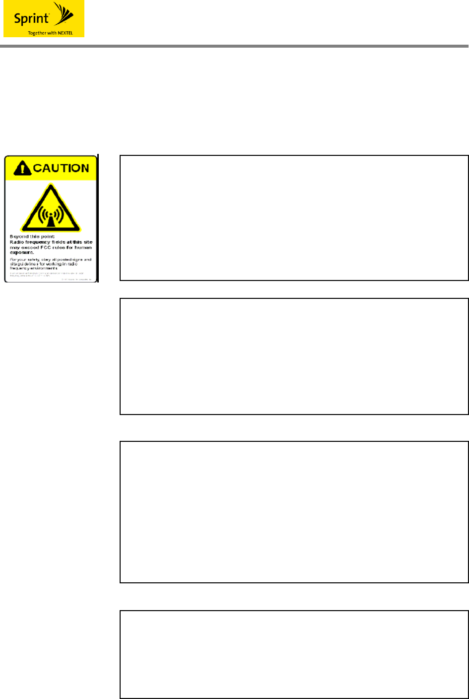
WARNING! EXPOSURE TO RF
Working with the repeater while in operation, may expose the technician to
RF electromagnetic fields that exceed FCC rules for human exposure. Visit
the FCC website at www.fcc.gov/oet/rfsafety to learn more about the effects of
exposure to RF electromagnetic fields.
RF EXPOSURE & ANTENNA PLACEMENT
Actual separation distance is determined upon gain of antenna used.
Please maintain a minimum safe distance of at least 20 cm while operating near the
donor and the server antennas. Also, the donor antenna needs to be mounted
outdoors on a permanent structure.
FCC STATEMENT
This equipment has been tested and found to comply with the limits for a Class A
digital device, pursuant to Part 15 of the FCC Rules. These limits are designed to
provide reasonable protection against harmful interference when the equipment is
operated in a commercial environment. This equipment generates, uses, and can
radiate radio frequency energy and, if not installed and used in accordance with the
instruction manual, may cause harmful interference to radio communications.
Operation of this equipment in a residential area is likely to cause harmful
interference in which case the user will be required to correct the interference at
own expense.
Warning!
This equipment generates or uses radio frequency energy.
Changes or modifications to this equipment may cause harmful interference unless
the modifications are expressly approved in the instruction manual. The user could
lose the authority to operate this equipment if an unauthorized change or
modification is made.

iDEN
Lists of Contents
1. OVERVIEWS...............................................................................................................7
2. SYSTEM NETWORK CONFIGURATION ...................................................................8
2.1 APPLICATION SCOPED.......................................................................................8
2.2 FREQUENCIES USED..........................................................................................9
3. SYSTEM SPECIFICATIONS AND STANDARDS .....................................................10
3.1. SYSTEM SPECIFICATIONS ...............................................................................10
4. SYSTEM SHAPE AND FUNCTIONS........................................................................12
4.1 SYSTEM SHAPE.................................................................................................12
4.2 CABINETS ..........................................................................................................12
4.3 SYSTEM CONFIGURATION AND FUNCTIONS.................................................16
5. SYSTEM BLOCK......................................................................................................19
5.1 BLOCK DIAGRAM..............................................................................................19
5.2 INTERPRETATION OF BLOCK DIAGRAMS......................................................19
6. NMS ..........................................................................................................................21
6.1 NMS.....................................................................................................................21
6.2 NMS STANDARDS .............................................................................................21
6.3 FUNCTION DESCRIPTION.................................................................................21
7. GUI (GRAPHIC USER INTERFACE) ........................................................................24
7.1 PROGRAM INSTALLATION ...............................................................................24

iDEN
7.2 PROGRAM START .............................................................................................27
7.3 STATUS INQUIRY/SETTING...............................................................................27
7.4 DOWNLOAD .......................................................................................................29
8. SYSTEM INSTALLATION.........................................................................................33
8.1 CONFIRMATION OF SYSTEM COMPONENTS.................................................33
8.2 PRECAUTIONS DURING INSTALLATION OF THE SYSTEM ...........................33
9. SYSTEM SETUP AND CHECKUP............................................................................34
9.1 CHECK ITEMS DURING OPENING ...................................................................34
9.2 TROUBLES AND CHECKUP..............................................................................35
☎ CONTACT PLACE OF THE MAKER.......................................................................37

iDEN
- Lists of Figures -
<Fig. 1 > iDEN network configuration..........................................................................8
< Fig. 2 > iDEN frequencies used.................................................................................9
< Fig. 3 > iDEN carrier characteristics.........................................................................9
< Fig. 4 > System shape..............................................................................................12
< Fig. 5 > External appearance of cabinets ...............................................................13
< Fig. 6 > Latch structure............................................................................................13
< Fig. 7 > Hinge functions...........................................................................................14
< Fig. 8 > Swing handle functions..............................................................................15
< Fig. 9 > Additional functions of cabinets................................................................15
< Fig. 10 > System configuration ...............................................................................16
<Fig. 11> Setup file......................................................................................................24
<Fig. 12 > Installation Start .........................................................................................24
<Fig. 13> Selection of an installation folder..............................................................25
<Fig. 14> Completion of preparation for installation................................................25
<Fig. 15> Display of program installation progress .................................................26
<Fig. 16> USB Driver Installation ...............................................................................26
<Fig. 17> USB Driver Installation ...............................................................................27
<Fig. 18 > Program start..............................................................................................27
<Fig. 19> An iDEN status inquiry screen...................................................................28
<Fig. 20> An iDEN status setting screen ...................................................................29
<Fig. 21> A download preparation window ...............................................................29
<Fig. 22> File Open......................................................................................................30
<Fig. 23> Completion of download preparation........................................................30
<Fig. 24> A download progress screen .....................................................................31
<Fig. 25> A message to notify you of download failure ...........................................31
<Fig. 26> Flash write wait ...........................................................................................31
<Fig. 27> Download completion.................................................................................32

iDEN
- Lists of Tables –
<Table 1 > iDEN frequencies used ...............................................................................9
<Table 2 > System specifications...............................................................................11
<Table 3 > Shape and functions.................................................................................11
<Table 4 > Environmental specifications...................................................................11

iDEN
1. Overviews
The iDEN (Integrated Digital Enhanced Network) RF repeater is a RF repeater for indoor use
using a frequency band of iDEN networks.
This is an ideal and economical RF repeater for customers who want expansion of
communication ranges while not reducing performance with a RF relay system by installing
repeaters inside buildings, parking lots in electromagnetic shade regions, etc.
This repeater is designed to be elastically applicable to any frequency of iDEN band, is
excellent in frequency selection levels of frequency bandwidth to service of down links and up
links through an up/down converter module, and minimizes interference in other signals.
The iDEN (Integrated Digital Enhanced Network) RF repeater CCD has a local repeater
control function to manage and control repeaters continuously for stable services of repeaters
installed at the site and a remote repeater control function to support remote monitoring and
control using a repeater integrated monitoring system.
The iDEN (Integrated Digital Enhanced Network) RF repeater is interlocked with the iDEN
repeater integrated monitoring system using a modem in order to be interlocked with the iDEN
repeater integrated monitoring system.
The basic structure of iDEN repeaters is composed of an input port and an output port. The
inside of repeaters was composed of a DL(Down Link) converter and UL(Up Link) converter as
one module for optimum sizes and high efficiency and composed of PSU(Power Supply Unit),
Filter Unit, NMS module, and PAU(Power Amplifier Unit).
All modules except PAU was commonly used for economy and efficiency of operation and it was
made possible to change system output with PAU replacement only.
iDEN
2. System Network Configuration
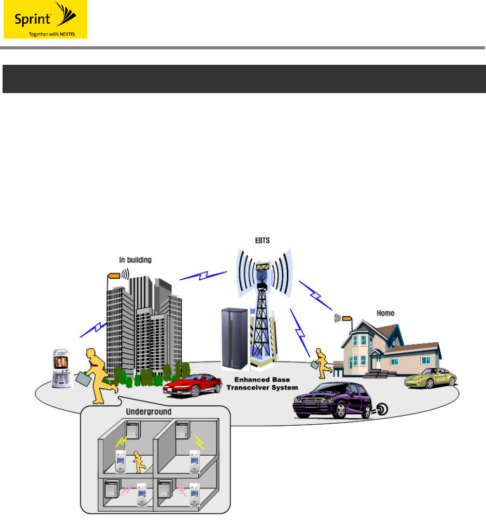
The iDEN RF repeater is an indoor relay device to receive and amplify the signals from
EBTS(Enhanced Base Transceiver System) wirelessly. The amplified signals secures cell
coverage and provides quality service for users by installing repeaters in various
electromagnetic shade regions that electromagnetic waves do not reach during expnasion of
communication zones of parking lots in buildings, households, etc. and by having them provide
services.
<Fig. 1 > iDEN network configuration
2.1 Application Scoped
The iDEN RF repeater aims to secure separate cell coverage and expand quality service
regions for users in order to provide mobile phone services inside a small-scale building and
underground space and transmit signals to various shade regions such as parking lots in
households, buildings, etc. by being installed where signals cannot reach or signals are weak.
iDEN
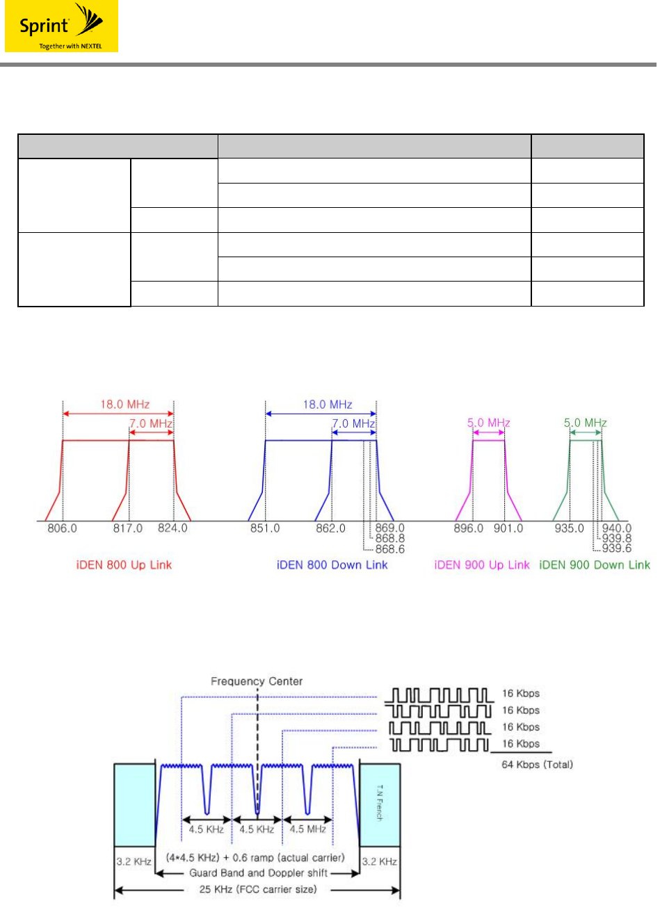
2.2 Frequencies Used
Items Standards Remarks
851 ~ 869 MHz 25kHz Step
800 MHz 862 ~ 869 MHz 25kHz Step
Down Link
900 MHz 935 ~ 940 MHz 25kHz Step
806 ~ 824 MHz 25kHz Step
800 MHz 817 ~ 824 MHz 25kHz Step
Up Link
900 MHz 896 ~ 901 MHz 25kHz Step
<Table 1 > iDEN frequencies used
< Fig. 2 > iDEN frequencies used
< Fig. 3 > iDEN carrier characteristics

iDEN
3. System Specifications and Standards
3.1. System Specifications
3.1.1 System standards
Items Standards Remarks
800MHz
Downlink : 851~869MHz
(Ability to switch 862~869 MHz)
Uplink : 806~824MHz
(Ability to switch 817~824 MHz)
25kHz Step
Frequency
Range
900MHz Downlink : 935~940MHz
Uplink : 896~901MHz 25kHz Step
65dB / 15dBm ※ iDEN(65/15)
65dB / 25dBm ※ iDEN(65/25)
Amplifier Gain /
Output Power per Band
80dB / 30dBm ※ iDEN(80/30)
-25 ~ -50dBm / Total ※ iDEN(65/15)
-15 ~ -40dBm / Total ※ iDEN(65/25)
Input Level
-20 ~ -50dBm / Total ※ iDEN(80/30)
Ripple 2.5 dB p-p
25dB(1dB/Step±0.5dB or less) ※ iDEN(65/15),(65/25)
Gain Control Range
30 dB(1dB/Step±0.5dB or less ※ iDEN(80/30)
Roll offs Δ65dBc or more @Band Edge± 500 KHz
1 carrier
25KHz : 50dBc
50KHz : 55dBc
500KHz : 55dBc
1MHz : 55dBc
2MHz : 55dBc
Downlink
Adjacent
Power
8carriers
25KHz : 47dBc
50KHz : 52dBc
500KHz : 52dBc
1MHz : 52dBc
2MHz : 52dBc
Out of band paging
carrier rejection
929~932MHz(3MHz),
940~941MHz(1MHz)
900MHz Inter modulation 1870~1880MHz/-105dBm 900MHz only
Spurious RF Emission -13dBm or less
Propagation Delay 8us or less
iDEN
5dB or less @Gain 65dB(Uplink)
Noise Figure
12dB or less @Gain 40dB(Uplink)
VSWR 1.5 : 1
Input/output connector N-Type (Female)
Input/output impedance 50Ω
Power 108 ~ 127 VAC, 60Hz
※Option
-40 to -60VDC
20 to 30 VDC
<Table 2 > System specifications
3.1.2 Shape
Items Standards
Cabinet Indoor type
RF connector Type(IN/OUT) N-Type Female
390*326*190 mm ※ iDEN(65/15)
390*326*210 mm ※ iDEN(65/25)
Size
(H*W*D)
390*326*240 mm ※ iDEN(80/30)
18.5 Kg ※ iDEN(65/15)
20.0 Kg ※ iDEN(65/25)
Weight
21.82 Kg ※ iDEN(80/30)
<Table 3 > Shape and functions
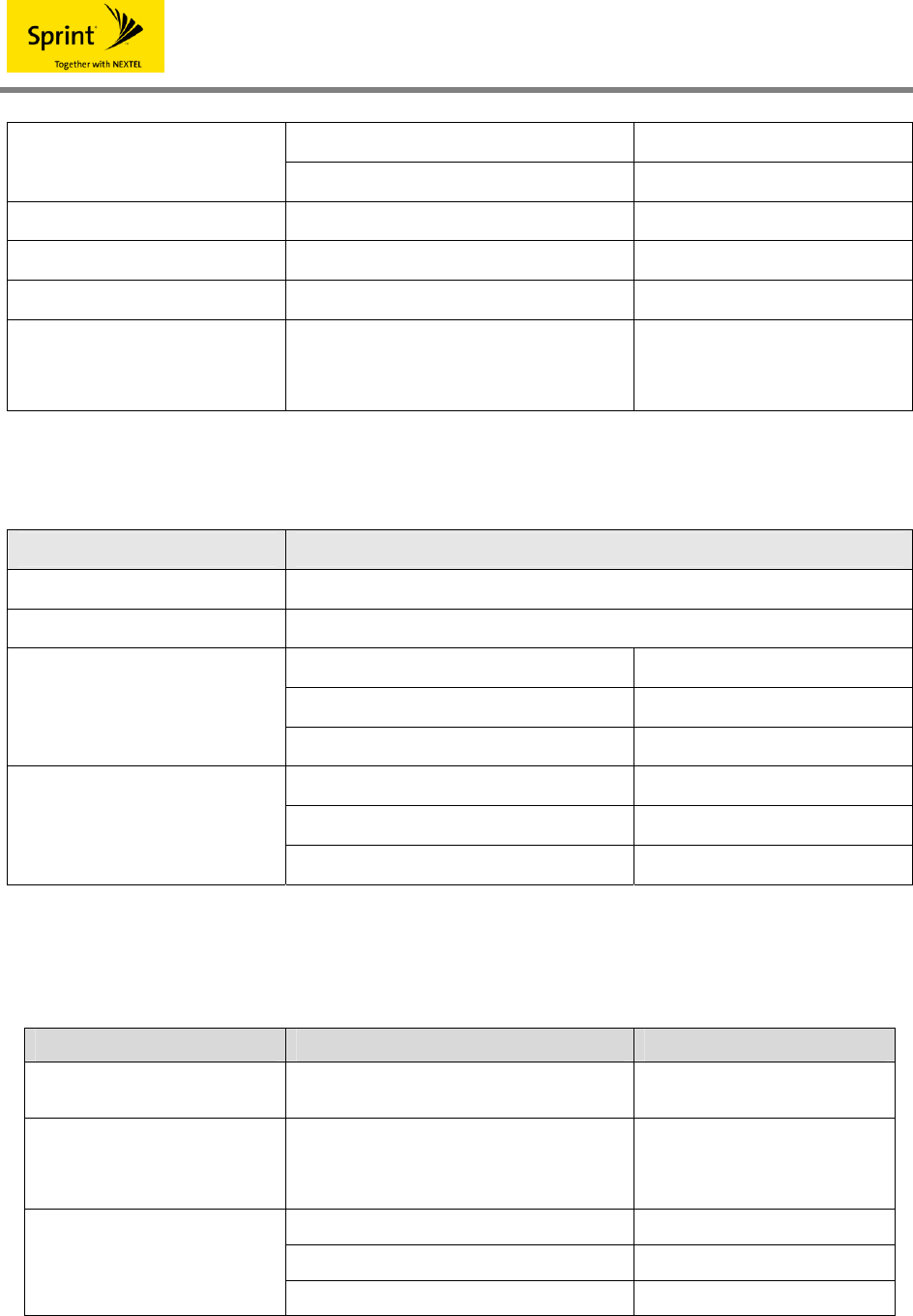
3.1.3 Environmental specifications
Items Standards Remarks
Working temperature/
working humidity -10℃ ~ 50℃ / 5 % ~ 95% Temperature and humidity
around cabinets
Power 108 ~ 127 VAC, 60Hz
※Option
-40 to -60VDC
20 to 30 VDC
TBD ※ iDEN(65/15)
TBD ※ iDEN(65/25)
Power consumed
TBD ※ iDEN(80/30)
< Table 4 > Environmental specifications
iDEN
4. System Shape and Functions
4.1 System Shape
The iDEN (Integrated Digital Enhanced Network) RF repeater was arranged to efficiently utilize
component modules when operators compose and operate the iDEN service network.
The iDEN RF repeater is basically installed on the wall, has a structure to be installed on a 19
inch rack as necessary, and is provided with ground terminals on the lower part of repeaters for
grounding.
< Fig. 4 > System shape
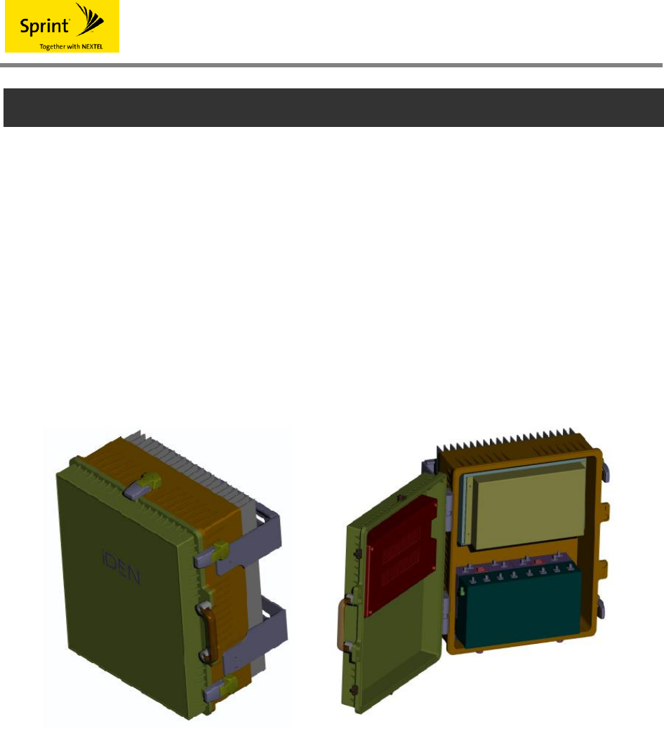
4.2 Cabinets
The cabinet of repeaters is made of a die-casting structure and enables component modules to
be installed on the door part in order to enhance attachment efficiency and minimize cabinet
sizes.
The heat radiation fins of repeaters have excellent heat radiation effects by determining the
length of fins for radiation of generated heat depending on output capacity.
iDEN
< Fig. 5 > External appearance of cabinets
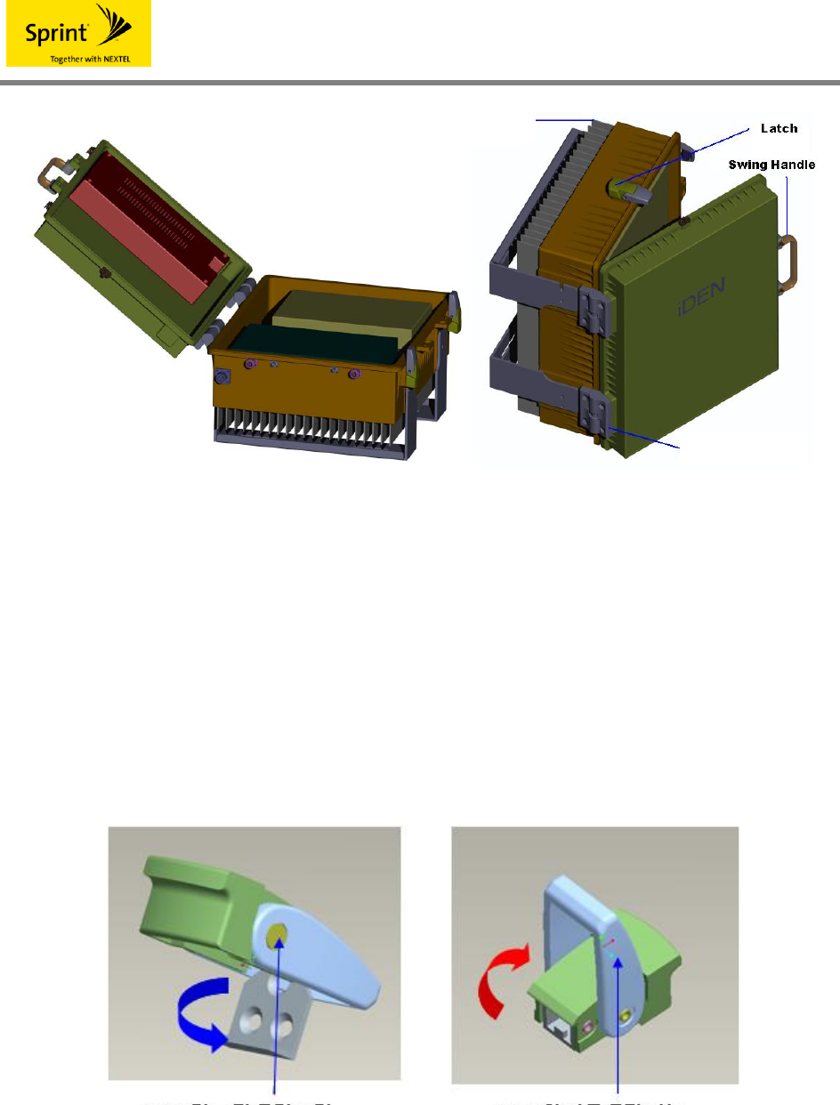
4.3.1 Latch
Latches was made to improve airtightness in performing a role important for cabinet
characteristics such as rain-proofing functions, vibration, etc. and to secure safety because of
locks.
It was made convenient in opening or closing doors with an automatic raising function of heads
and was made to avoid swing by minimizing shaft gap of latches.
< Fig. 6 > Latch structure
Hinge
Heat radiation fin
Shaft strength and gap
reinforcement An automatic raising function of
heads
iDEN
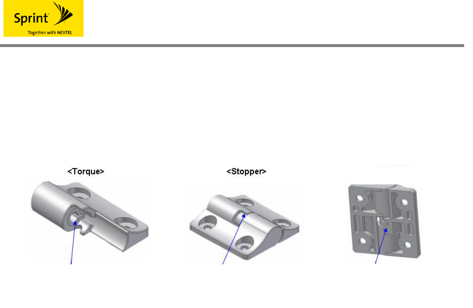
4.3.2 Hinge
This was designed by considering convenience and promptness when opening and closing
cabinets during assembly and maintenance of cabinets and has 3 kinds of advantages such as
a torque function, stopper function, and separated angle function.
< Fig. 7 > Hinge functions
(1) Torque function
Safety of repeater operator was considered by preventing abrupt door opening and closing
phenomena during assembly and operation via realization of torque functions.
(2) Stopper function
It was made to prevent damage to cabinets due to abrupt door opening during maintenance
after assembly and installation at sites via realization of stopper functions and this is made
of a double safety structure endowed with a stopper function by additionally designing
grooves for preventing opening.
(3) Separated angle function
A function was given to disable separation when the door is closed and enable separation of
the door part main body part of cabinets when the door is opened in a certain angle(about
20~30 degrees) by adding a notch at the central lower part of hinges.
4.3.3 Swing Handle
This used a folding type of handle for safety and convenience during transportation of cabinets
and enables it to be folded inwards after installation so as to be excellent in beauty.
This was endowed with convenience to enable a backwardly raised use when opening, closing,
or transporting the door of cabinets. The strength of handles was considered by considering
< Separated angle>
Torque function realization A stopper function when
opening cabinets Separation when opening
cabinets
iDEN
equipment weight for safety during transportation.
< Fig. 8 > Swing handle functions
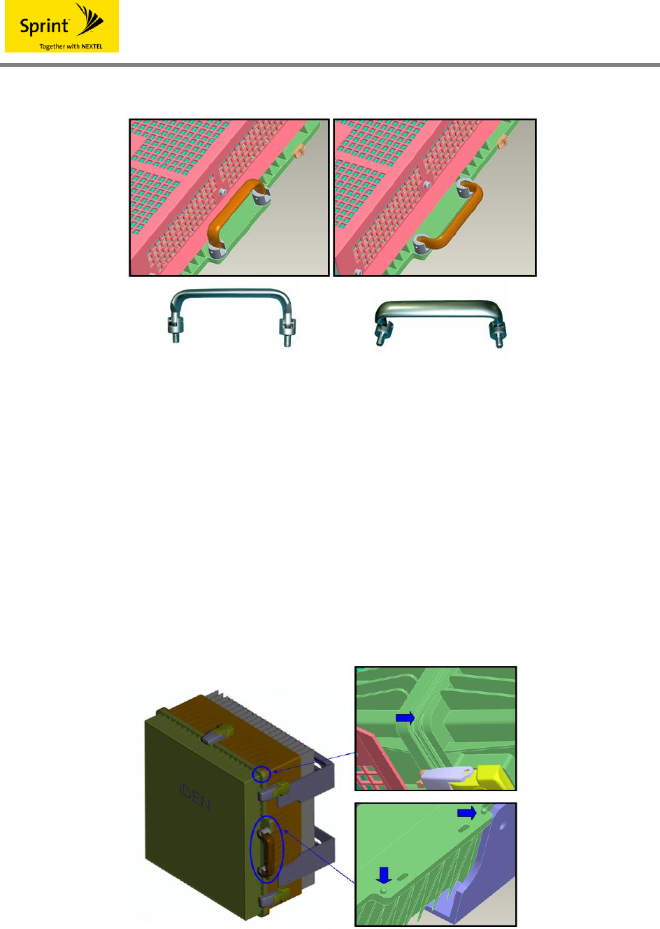
4.3.4 Additional functions
(1) A twist preventing sill
Realized in door part was a twist preventing sill for preventing a twist phenomenon of
repeater cabinets due to vibrations and external environmental factors after installation.
(2) Guide
This has a guide function to prevent twist after assembly between cabinets and has an
excellent heat transfer effect by expanding the contact area between the door and main
body part of cabinets simultaneously.
< Fig. 9 > Additional functions of cabinets
iDEN
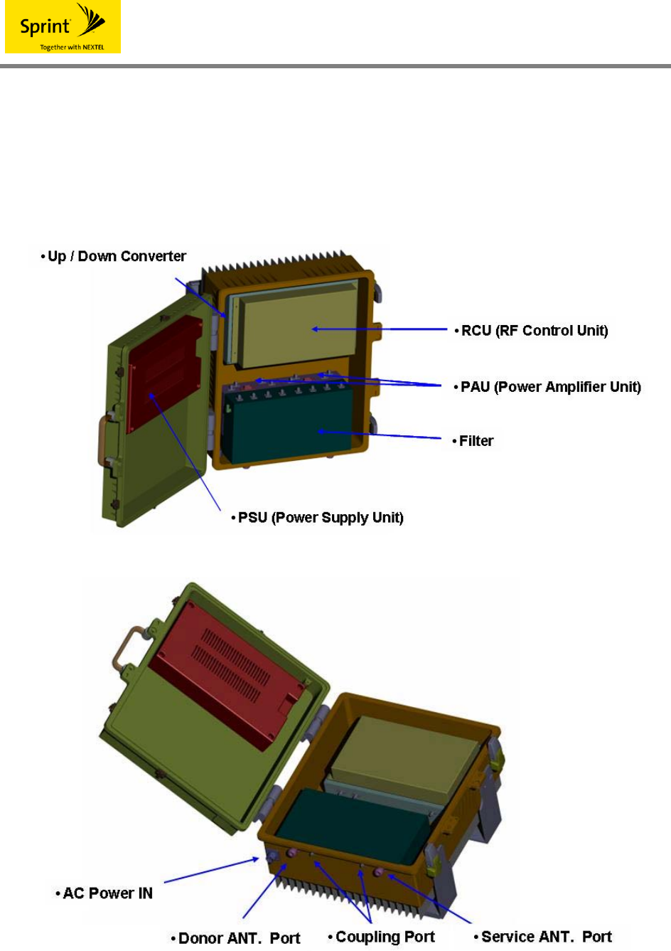
4.3 System configuration and functions
The iDEN (Integrated Digital Enhanced Network) RF repeater is composed of PSU(Power
Supply Unit), RCU(RF Control Unit), Up / Down Converter Module, PAU(Power Amplifier Unit),
Filter, and Isolator Check module.
< Fig. 10 > System configuration

iDEN
4.3.1 PSU (Power Supply Unit)
This is used to supply stable DC power to each device provided with active elements through
A/D conversion and D/D conversion by receiving AC power, uses semiconductors for industry or
higher in terms of major activation elements, is mechanically strong, and satisfies all electrical
characteristics. A power used, it is supposed to receive 108~127VAC, convert to DC 3.8V, DC
7V, DC 12 and DC 27V, and then use it.
And, the controller uses replaceable batteries and improper replacement can bring about
explosion, so dispose of the used batteries safely.
4.3.2 Controller
A controller is composed of RCU(RF Control Unit) and NCU(Network Control Unit) and plays a
role to monitor and control the status of each module of iDEN repeater.
The RCU(RF Control Unit) is connected to GUI through DEBUG port and can collect and control
the status monitoring information of modules.
NCU(Network Control Unit) enables the upper NMS(Ethernet) communication through the RJ-
45 port and can monitor and control status. The front face of NCU is provided with LED to
display the status so as to confirm existence of abnormality in modules easily.
CAUTION※
Improper replacement of batteries can bring about risk of explosion.
Dispose of used batteries according to manufacturer’s instructions.
4.3.3 Filter
This is connected to donor ANT of iDEN repeaters as a cavity type of filter and has only the
desired bands among the signals from the base station(EBTS) received through antenna pass
selectively, so as to remove other bands, secure isolation between DL and UL enough, and
have only the bands to service inputted through the LNA terminal. Besides, in the reverse
direction(Up Link), it works to minimize the spurious radiation power generated by PAU.
4.3.4 Up / Down Converter Module
The Up / Down Converter Module is composed of a down converter, up converter, and digital
filter of variable bandwidth from the filter to the PAU input in the down link and up link of iDEN
repeaters. Besides, this is composed of a pair of equal structure in order to deal with two bands
of 900M and 800M.

iDEN
The up/down converter of Down Link was realized with a digital filter through conversion and
A/D conversion with IF frequencies(62.5MHz) for the base station(EBTS) signals inputted
through the LNA part.
This picks up an excellent roll off characteristic with a digital filter, minimizes influence on other
signals by intercepting other neighbor bands and signals, and is improved to remove and
separate spurious waves.
And, the Up Link takes a roll off characteristic of a SAW filter by converting RF signals at the
inputted terminal to IF frequencies(70MHz) through LNA differently from the Down Link,
minimizes influence on other signals by suppressing neighbor signals, and is improved to
remove and separate spurious waves.
This suppresses leakage of local signals to the input terminal by inserting a band passage filter
at the front side of mixers. The mixer minimizes IMD components of a system by applying an
element that has a characteristic of High IP3 and minimizes influence on the next step by
maintaining linearity. The base station(EBTS) signal converted to a IF frequency is recovered to
the original frequency through the up converter.
The local step for IF conversion is designed to minimize phase noises in order not to reduce
quality(ρ value) of waveform that can take place during the conversion process of signals.
The RF block of the up/down converter of the down link performs AGC and ALC functions to
protect equipment during application of over input to the iDEN RF repeater, enables the on/off
function according to necessity from users, and has an automatic compensation function of
gains with respect to the temperature of a system.
4.3.5 PAU (Power Amplifier Unit)
PAU applied elements with reliability, durability, and good and high P1dB by considering the
spurious characteristics, is always monitoring the output by being connected to the control part
of a system, enables reporting to its superiors during occurrence of major items, and enables
the on/off of PAU operation according to the necessity from users.
The Down Link PAU amplifies iDEN signals to a proper output level and provides the VSWR
information of repeater output level and output port for the Control board.
Besides, this monitors the normal operation status of modules by providing Control boards with
the information on its temperature detection and device failure.
iDEN
5. SYSTEM BLOCK
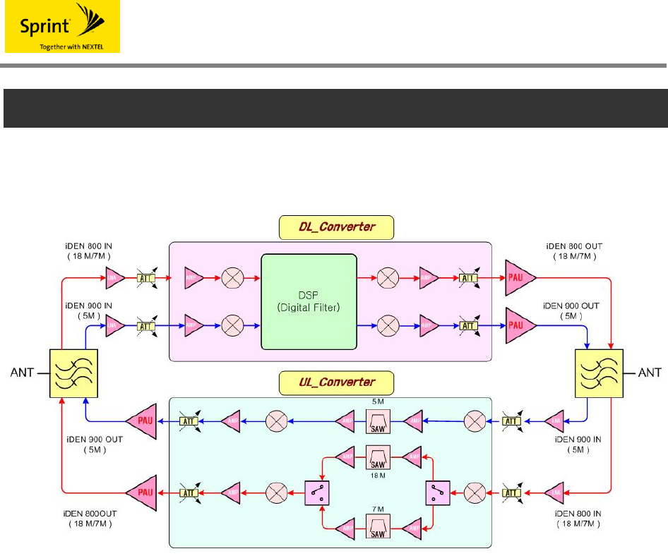
5.1 Block Diagram
<Fig. 14 > Block Diagram
5.2 Interpretation of Block Diagrams
Filter is a cavity type that is connected to the donor ANT and service ANT of iDEN repeaters and
has only the desired bands pass selectively among the base station(EBTS) signals and terminal
signals received through antenna.
The Up / Down Converter Module is composed of a down converter, up converter, and digital
filter of variable bandwidth from the filter to the PAU input in the down link and up link of iDEN
repeaters. Besides, this is composed of a pair of equal structure in order to deal with two bands
of 900M and 800M.
The up/down converter of Down Link was realized with a digital filter through conversion and
A/D conversion with IF frequencies(62.5MHz) for the base station(EBTS) signals inputted
through the LNA part.
This picks up an excellent roll off characteristic with a digital filter, minimizes influence on other
signals by intercepting other neighbor bands and signals, and is improved to remove and
separate spurious waves.

iDEN
And, the Up Link takes a roll off characteristic of a SAW filter by converting RF signals at the
inputted terminal to IF frequencies(70MHz) through LNA differently from the Down Link,
minimizes influence on other signals by suppressing neighbor signals, and is improved to
remove and separate spurious waves.
PAU amplifies the iDEN signals to a proper output level with a module at the final step of
wndrPrldml, pass through a filter, and then discharges it through ANT.
iDEN
6. NMS
6.1 NMS
NMS is composed of RCU(RF Control Unit) and NCU(Network Control Unit) and plays a role to
monitor and control the status of each module of iDEN repeater.
The RCU(RF Control Unit) is connected to GUI through DEBUG port and can collect and control
the status monitoring information of modules.
NCU(Network Control Unit) enables the upper NMS(Ethernet) communication through the RJ-
45 port and can monitor and control status. The front face of NCU is provided with LED to
display the status so as to confirm existence of abnormality in modules easily.
6.2 NMS standards
6.2.1 Electrical standards
Items Standards Remarks
Input power +7V / 1A / ±5 %
Electrical characteristics Power used +5V, +3.3V, +1.8V,
6.2.2 Physical standards
Items Contents
External sizes of RCU 200*110
External sizes of NCU 200*110
Board sizes
Thickness, layer 1.6T, 4 Layer
6.3 Function description
6.3.1 ALC functions
This is a function to stably operate repeaters and base stations by preventing repeater output
from exceeding its setup limit.
(1) Handling procedures

iDEN
a. Turn on/off the ALC function setup through GUI.
b. Compensate its difference when the forward output value is greater than the set level or
less than 1dB.
c. Compensate its difference when the backward output value is greater than the set level
or less than 1dB.
d. Monitor the forward and backward output values every 1 second.
(2) References
a. Forward and backward operations are independent of each other.
b. It does not work during oscillation checkup.
6.3.2 Shutdown functions
This is a function to shut it down for stable protection of repeaters when the repeater output
exceeds its setup limit.
(1) Handling procedures
a. This works when the forward and backward output values are 3dB (iDEN Shutdown
Level) higher than the ALC setup limit.
b. Perform the first shutdown operation by turning off PAU when output is in an operation
condition for 5 seconds by monitoring output for 5 seconds.
c. Perform PAU ON operation 5 seconds after shutdown.
d. Wait until output is stabilized for 1 second and then monitor output for 4 seconds.
e. When output works for 4 seconds, turn off PAU and then perform the second shutdown
operation.
f. Perform No.d,e,f operation until 3 times
g. When the PAU ON waiting time is 30 minutes after the last 3rd operation and the next
step is a shutdown condition, proceed with it in a complete shutdown condition.
h. In case of a complete shutdown condition, it is possible to come out of the complete
shutdown condition only by turning on/off the repeater directory or setting PAU ON.
(2) References
a. It does not work when the ALC operation setup is off.
b. Forward and backward operations are independent of each other.

iDEN
6.3.3 Oscillation Check functions
(1) Handling procedures
a. Turn on/off the oscillation check function setting through GUI.
b. Inspect the 798 ~ 799MHz section
c. Measure the oscillation detection values while moving by 30KHz from the oscillation
check frequency 798 ~ 799MHz.
d. Find the minimum value and maximum value among the values measured in c.
e. When the difference between the maximum value and minimum value is 0dB greater
than the setting value, compensate the gain by the difference.
f. When the difference between the maximum value and minimum value is -1dB less
than the setting value, compensate the gain by -0.5dB.
(2) References
a. This does not work during operation of channel scan.
b. When ALC works, have the gain compensation value not exceed the ALC setting level.
c. When the backward ALC operation is off, operate it by interlocking it with the forward
gain.
6.3.4 Oscillation Shutdown function
(1) Handling procedure
a. Operate it when the oscillation attendance is 30dB or higher.
b. Turn off all PAUs and generate alarm.
c. After 10 seconds, return the PAU to the original state and perform the oscillation check
function.
d. If the shutdown condition continues, perform it up to 3 times and thereafter get into a
complete shutdown state.
e. If it is a complete shutdown state, you can come out of the complete shutdown state
only by turning off/on the repeater directly or setting the PAU ON.
(2) References
a. This works only when the oscillation check function is ON.
iDEN
7. GUI (Graphic User Interface)
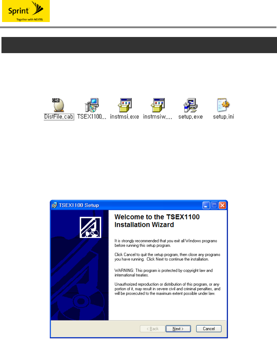
7.1 Program Installation
Prepare the provided installation program in the same folder as below.
<Fig. 11> Setup file
Start program installation by double-clicking Setup.exe.
Then, the following screen will show up. In order to cancel the installation, click [Cancel] in the
right lower side, and in order to continue the installation, click [Next].
<Fig. 12 > Installation Start
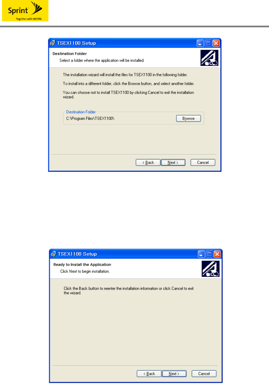
Select a folder where the program will be installed.
Basically, a folder called C:\Program Files\TSEX1100 is created, allowing installation of a
program there. In order to change an installation folder, select a desired folder by pressing
[Browse] button and then change it.
iDEN
<Fig. 13> Selection of an installation folder
When an installation folder is determined, click the [Next] button.
Then, a window to inform you that the preparation for installation has been completed will show
up as follows.
<Fig. 14> Completion of preparation for installation
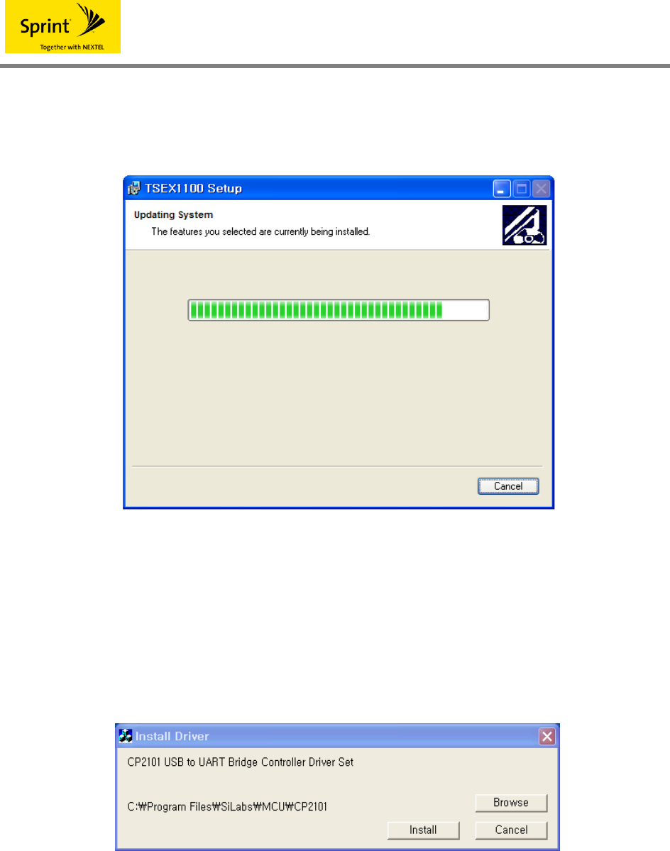
In order to change an installation folder, click the [Back] button, go over to the <Fig. 14> screen,
iDEN
and then change the installation folder. In order to continue installation, click [Next] button. Then,
a program is automatically installed as shown in <Fig.16>.
<Fig. 15> Display of program installation progress
It is asked whether or not to install a USB driver.
In order to install a USB driver, proceed with installation according to the installation procedure
by clicking the [Install] button, and if a USB driver has been already installed, cancel the
installation by clicking the [Cancel] button.
<Fig. 16> USB Driver Installation
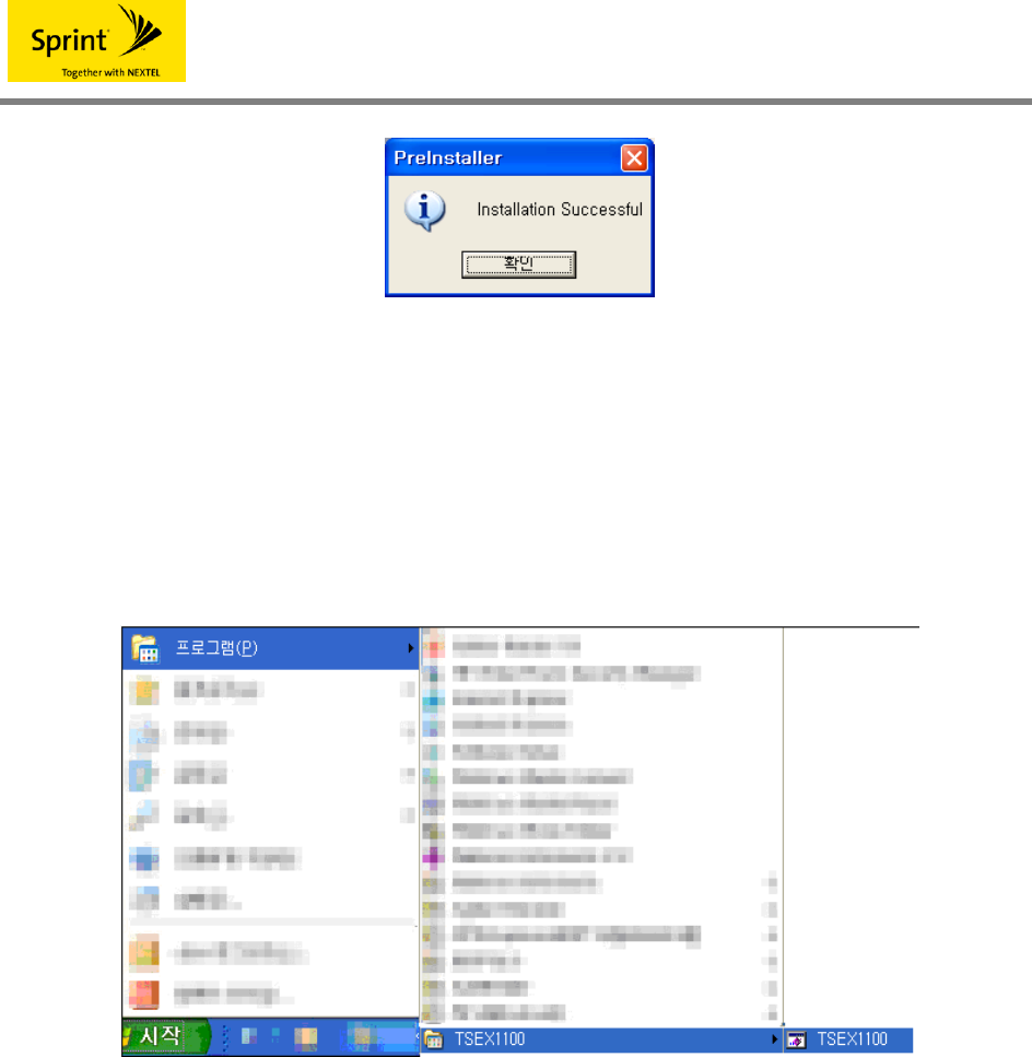
When the program installation is finished, an installation completion message window shows up
as shown in <Fig. 18>.
End the installation by clicking the [confirm] button.
iDEN
<Fig. 17> USB Driver Installation
7.2 Program Start
If the program is properly installed, then go to Start->Program on the Windows menu and
execute TSEX1100.
<Fig. 18 > Program start
7.3 Status Inquiry/Setting
As soon as the program is executed, a serial port is automatically opened at a baudrate
38400bps.
In order to change the comport, suspend the present status by pressing the [Port Close] button,
change it into the desired port among COM 1 ~ COM 8, and then open the port by clicking the
[Port Open] button.
You can know the communication status through TXD / RXD LED in the right upper side.
If TXD / RXD flickers in turns, it means that communication is properly being realized.
PC displays the status values on the screen while automatically polling with the system in about
iDEN
1 second interval.
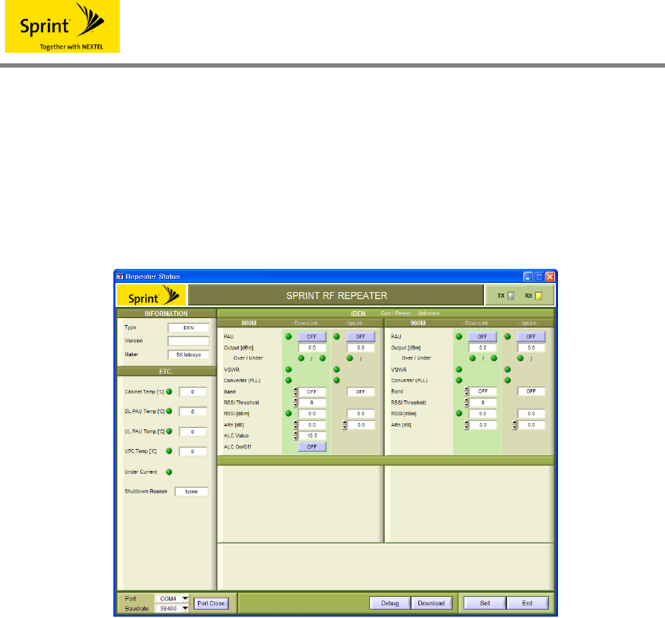
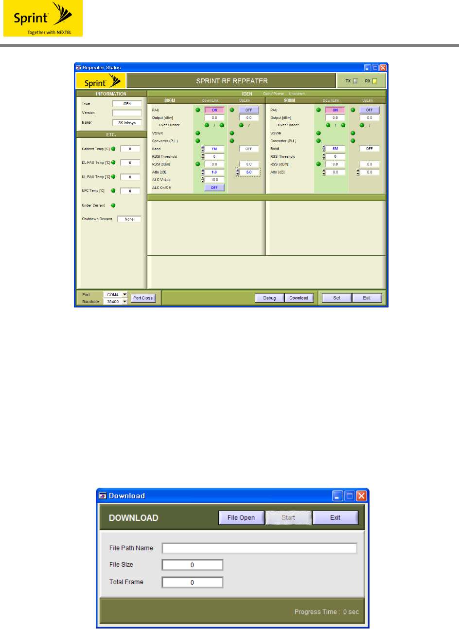
7.3.1 Status Inquiry
If the type in the left upper side is iDEN, an iDEN related item appears on the screen as shown
in the figure below.
<Fig. 19> An iDEN status inquiry screen
Functions of each button are as follows.
Port Open / Close Opening/closing a communication port
Debug Opening a window to show communication contents
Download Opening a download window
Set Control setting
Exit Program end
7.3.2 Status Setting
Changing the value of the item to change when controlling status changes the item text into blue
color as shown in the figure below, and pressing the [Set] button changes values for the item
whose text has changed into blue color.
iDEN
<Fig. 20> An iDEN status setting screen
7.4 DOWNLOAD
7.4.1 Preparation for Download
Clicking the Download button on the status/monitoring screen enables F/W Download.
Clicking the Download button on the status/monitoring screen shows a window as shown in the
figure below.
<Fig. 21> A download preparation window
Click the [File Open] button. If you want to end it, click the [Exit] button.
iDEN
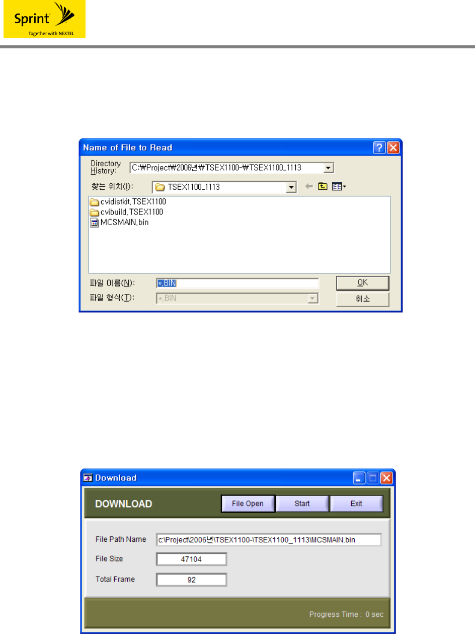
7.4.2 File Open
Clicking the [File Open] button shows a File Open window as shown in the figure below.
<Fig. 22> File Open
Find and click a file to download whose extension is ".bin” or directly enter the name of a file to
download on the file name column and then click [OK]. Then, the file information(file path, file
name, file size, total frame) will show up on the download preparation window as shown in the
figure below.
<Fig. 23> Completion of download preparation
iDEN
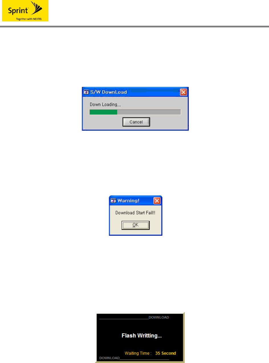
7.4.3 Download Start
Clicking the [Start] button on the upper side of the above <Fig. 24> starts downloading and
shows a download progress window as shown in the figure below to show the download
progress situations.
<Fig. 24> A download progress screen
Pressing the [Cancel] button cancels download. If downloading is not properly realized, a
warning window shows up as shown in the figure below.
<Fig. 25> A message to notify you of download failure
7.4.4 Completion of Download
If download is completed, a wait window shows up while equipment is being initialized. Wait
until a completion message appears.
<Fig. 26> Flash write wait

iDEN
If all download processes are completed, a completion message appears as below.
<Fig. 27> Download completion

iDEN
8. System Installation
8.1 Confirmation of System Components
a. Check the following matters during installation for normal operation of equipment.
b. Check existence of abnormality to see if the appearance of repeaters(RF connector), etc.
was deformed due to damage to the repeater packing materials during equipment
transportation.
c. Check if equipment components coincide with one another and check if the installation
place satisfies the working temperature and humidity of the equipment defined in the
product standards.
d. Confirm the input signal conditions of the equipment defined in the product standards.
8.2 Precautions during Installation of the System
In order to avoid occurrence of dangerous situations during installation of repeaters, be sure to
comply with the provided instruction manual by all means.
Especially, the power cord of this repeater is of an eternal connection type, so an easily
accessible power interruption device should be installed in the indoor wiring, and there should
be an easily accessible socket-outlet near the repeater.
Sequ
ence Description Precautions
1
Donor ANT attachment and
feeder cable installation
Service ANT or LCX installation
• When installing cables, perform the work so that there may
be no damage to the crust.
• Protect the connection part such as connectors, etc. with
insulation tapes in order to prevent invasion of moisture, etc.
• When installing the feeder cable, minimize the environmental
influence.
2 Installation of antenna for
donors
• Avoid twist in the antenna direction after construction by
fixing it rigidly by considering wind speed by regions.
3 Arrangement of power cables
and RF cables
• Prevent cable damage due to bending or extension of
cables.

iDEN
9. System Setup and Checkup
9.1 Check Items during Opening
9.1.1 Check Items before Opening
(1) Check the normal power of AC108~127 VAC and then check existence of abnormality
in power cables.
(2) Check if the donor RF input signal from outside is in a normal level.
Caution: If a system is operated without confirming input signals, serious damage may ※
be caused to the amplification elements due to saturation of output signals, so
operate the equipment after checking the input signal level by equipment and
the ALC ON status of equipment(ALC ON during product shipment) by all means.
(3) Plug AC108~127 V into the power connector of equipment and then turn on the
equipment power switch.
(4) Confirm existence of abnormality by checking the status of alarm LED lighting in the
GUI table or repeater front plate through notebooks.
(5) If the forward RF input signal from outside is judged to be in a normal level, turn off the
power switch of repeaters, connect the ANT feeder cables and service ANT(overhead
cable) to the input/output port of repeaters and then turn on the power switch of
repeaters again.
Caution: Make a connection by paying attention so that forward and backward ports may ※
not be changed for each other.
9.1.2 Check Items after Opening
(1) Confirm existence of abnormality by checking the alarm LED lighting status of repeaters.
(2) Check whether the RF input/output value on NMS is normal or not using GUI.
(3) After about 10 minutes passes after turning on the repeater power, measure the
spurious wave characteristic, etc. of forward and backward output of repeaters using
spectrum waveform analyzer by using the coupling terminal beside each input/output
port of repeaters and confirm the normal operation status of repeaters.
(4) After normal operation of repeaters, measure the communication quality at the service
region using terminals or testers and optimize the wave environment while comparing it
with the status before opening by seeing if there is no wave shade region or
communication impossibility region.

iDEN
9.2 Troubles and Checkup
9.2.1 Repeater Checkup
When checking repeaters periodically or due to abnormality in service, check the existence of
abnormality in the equipment according to the following sequence.
(1) Confirm the RF input/output level of repeaters on NMS, LED of repeaters, etc. using
GUI, measure communication quality using terminals or testers in case of regular
inspection, and follow the following procedures even though the RF input/output level of
repeaters on NMS is normal when abnormality takes place in service.
(2) Check the output status by connecting a wave analyzer to the test terminal of repeaters.
(3) Check the output values using the coupling port.
(4) Check if the repeater output value confirmed by a waveform analyzer coincides with the
actual repeater output value.
(5) If the output value measured by a waveform analyzer does not coincide with the actual
setting value, check the repeater input level.
(6) If the input level is not equal to the previous setting and there is a remarkable difference
in the input level, check the antenna attachment status and the feeder cable installation
status.
(7) If there is abnormality in the repeater output value by comparing the input level with the
repeater operation gain, turn on/off the repeater power switch, confirm the output status
with a waveform analyzer again, and if it is a severe trouble, replace it with a spare part
so that there may be no trouble in providing normal service.
9.2.2 Facility Checkup
Parts and items to be check during regular checkup or during occurrence of abnormality in
service are as follows.

iDEN
Checkup parts Checkup items Remarks
Donor antenna and service
antenna
Check if there is no abnormality in the antenna
attachment status and if the received signal
intensity of donor antenna and the RSSI value
are good.
Feeder cables, leakage coaxial
cables
Check if there is no feeder cable, leakage
coaxial cable cutting, coating damage, etc.
Connectors, distributors
Check if there is no flooding phenomenon in
connector connection parts and cables and if
each connection part is rigidly tightened.
Power input parts Confirm existence of a short circuit in normal
power terminal boxes of 108 ~ 127 VAC.

iDEN
Contact place of the maker ☎
Maker
SK Telesys Co., Ltd.
Address Chorim building, 6-3 Sunae-dong, Boondang-gu, Seongnam-city,
Gyeonggi-do, Korea
Staff in charge
of R&D 82-31-786-5625 manager Jae-Hyung Kim
Staff in charge
of sales