SKF USA 2012 Wireless Condition Monitoring Node User Manual
SKF USA Inc. Wireless Condition Monitoring Node
SKF USA >
User manual

SKF Wireless Machine Condition Sensor
Supports CMWA 8800
P/N 32257600-EN
Revision A
System Setup Guide
Copyright 2012 by SKF USA Inc.
All rights reserved.
5271 Viewridge Court, San Diego, CA 92123-1841 USA
Telephone: (858) 496-3400, Fax: (858) 496-3531
Customer Service: 1-800-523-7514

SKF USA Inc.
® SKF is a registered trademark of the SKF Group.
All other trademarks are the property of their respective owners.
© SKF 2012
The contents of this publication are the copyright of the publisher and may not be
reproduced (even extracts) unless prior written permission is granted. Every care has
been taken to ensure the accuracy of the information contained in this publication but
no liability can be accepted for any loss or damage whether direct, indirect or
consequential arising out of the use of the information contained herein. SKF reserves
the right to alter any part of this publication without prior notice.
SKF Patents include: #US04768380 • #US05679900 • #US05845230 •
#US05854553 • #US05992237 • #US06006164 • #US06199422 •
#US06202491 • #US06275781 • #US06489884 • #US06513386 •
#US06633822 • #US6,789,025 • #US6,792,360 • US 5,633,811 • US 5,870,699 •
#WO_03_048714A1
Product Support – Contact Information
Product Support – To request a Return Authorization, Product Calibration or a Product
Support Plan, use the web page links for direct contact and support.
Product Sales - For information on purchasing condition monitoring products, services
or customer support, contact your local SKF sales office.
General Product Information
For general product information (i.e., product data sheet, accessories catalog, etc.), visit
the Condition Monitoring Products page on SKF.com and select the appropriate product
link.
Technical Support Group
For technical support on issues like troubleshooting product installation, troubleshooting
product performance, etc., use our technical support web page to contact one of our
Technical Support Groups.
Product Registration
Please take a moment to register your product at www.skf.com/cm/register to receive
exclusive benefits offered only to our registered customers, including receiving technical
support, tracking your proof of ownership, and staying informed about upgrades and
special offers. (Please visit our website for more details on these benefits.)
Tell us how we’re doing!
It’s important that you’re satisfied with the quality of our product user manuals. We
appreciate your feedback; if you have comments or suggestions for improvement, please
tell us how we’re doing!
051012ds
SKF USA Inc.
Limited Warranty
WARRANTY
Subject to the terms and conditions contained
herein, SKF warrants to the Buyer that for the
warranty period indicated below the products
sold by SKF that are listed below (the
“Products”), when properly installed, maintained
and operated, will be free from defects in
material and workmanship and shall be fit for
the ordinary purposes for which the Products
are designed.
BUYER’S LIMITED REMEDIES
This limited warranty defines SKF’s sole and
exclusive liability and Buyer’s sole and exclusive
remedy for any claim arising out of, or related
to, any alleged deficiency in any Product sold by
SKF, even if such claim is based on tort
(including negligence or strict liability), breach of
contract, or any other legal theory.
If the Product does not conform to this limited
warranty, Buyer must notify SKF or SKF’s
authorized service representative within thirty
(30) days of discovery of the nonconformity;
provided, however, that SKF shall not be liable
for any claim for which notice is received by SKF
more than thirty (30) days following the
expiration of the applicable warranty period for
the Product. Upon receipt of timely notification
from Buyer, SKF may, at its sole option, modify,
repair, replace the Product, or reimburse Buyer
for any payment made by Buyer to SKF for the
purchase price of the Product, with such
reimbursement being pro-rated over the
warranty period.
WARRANTY PERIOD
Except as expressly provided below, the
warranty period for each Product shall
commence on the date the Product is shipped
by SKF to Buyer.
90-DAY WARRANTY
Products warranted for ninety (90) days by SKF
are as follows: cable assemblies, MARLIN
QuickConnect (MQC), magnetic temperature
probes, and all refurbished equipment.
ONE-YEAR WARRANTY
Products warranted for one (1) year by SKF are
as follows: all Microlog products and
accessories, all Microlog Inspector applications
including hand-held computers, all MARLIN
data managers (MDM), all MARLIN Condition
Detectors (MCD), all Wireless Machine Condition
Detectors (WMCD), all Multilog On-line Systems
(IMx), all Multilog Condition Monitoring Units
(CMU, TMU), Multilog Local Monitoring Units
(LMU), all Multilog Wireless Monitoring Units
(WMx), all Wireless Monitoring Systems V/T, all
Vibration PenPlus, all Machine Condition
Advisers, all transmitters, all Monitor Interface
Modules (MIM), all Machine Condition
Transmitters (MCT), MicroVibe P and Custom
Products with the prefix of CMCP (with the
exception of any consumable or expendable
items), SKF Wireless Machine Condition Sensor,
Shaft Alignment Systems TKSA 60 and TKSA
80 including hand-held computer, measuring
units and accessories.
TWO-YEAR WARRANTY
Products warranted for two (2) years by SKF
are as follows: all standard Eddy Probes, Eddy
Probe Drivers, and Eddy Probe Extension
Cables, all Multilog On-line Systems (DMx), and
all M800A and VM600 Machinery Monitoring
Systems.
For all On-line Systems that have satisfied
Criteria 1 and 2 below, the warranty period shall
be either thirty (30) months from the date the
On-line System is shipped by SKF to Buyer, two
(2) years from the date the On-line System is
installed and commissioned by SKF, or two (2)
years from the date on which the installation of
the On-line System has been audited and
commissioned by SKF or its authorized service
representative, whichever period ends first.
Criteria 1. Devices used with a Multilog
On-line System (IMx), Multilog Condition
Monitoring Unit (CMU), Multilog Local
Monitoring Unit (LMU), including, but not limited
to, the sensing device, the interconnect cabling,
junction boxes, if any, and the communications
interface, must consist only of SKF-supplied or
SKF-approved devices and/or components. The
computer provided by Buyer must meet the
requirements stipulated by SKF.
Criteria 2. SKF or its authorized service
representative has installed the On-line System
or has audited the installation and
commissioned the On-line System.
“On-line Systems” are defined as systems
consisting of Multilog On-line System (IMx),
Multilog Condition Monitoring Unit(s) (CMU),
Multilog Local Monitoring Unit(s) (LMU), and any
sensing or input devices, the interconnect
cabling between the sensing or input devices
and the Multilog On-line System (IMx), Multilog
Condition Monitoring Unit(s) (CMU), Multilog
Local Monitoring Unit(s) (LMU), and the cabling
between the Multilog On-line System (IMx),
Multilog Condition Monitoring Unit (CMU),
Multilog Local Monitoring Unit (LMU) and the
proprietary SKF communications interface with
the host computer.
FIVE-YEAR WARRANTY
Products warranted for five (5) years by SKF are
as follows: all standard seismic sensors
(accelerometers and velocity transducers).
OTHER SKF PRODUCTS
Any SKF product supplied hereunder but not
covered by this limited warranty shall be either
covered by the applicable SKF limited warranty
then in place for such product or, if no such
warranty exists, shall be covered by the 90-day
warranty stated above.
THIRD PARTY PRODUCT WARRANTIES
For any third party products sold to Buyer by
SKF, SKF will transfer to Buyer any warranties
made by the applicable third party product
vendor to the extent such warranties are
transferable.
CONDITIONS
As a condition to SKF’s warranty obligations
hereunder and if requested or authorized in
writing by SKF, Buyer shall forward to SKF any
Product claimed by Buyer as being defective.
Buyer shall prepay all transportation charges to
SKF’s factory or authorized service center. SKF
will bear the cost of shipping any replacement
Products to Buyer. Buyer agrees to pay SKF’s
invoice for the then-current price of any
replacement Product furnished to Buyer by
SKF, if the Product that was replaced is later
determined by SKF to conform to this limited
warranty.
SKF shall not be obligated under this limited
warranty or otherwise for normal wear and tear
or for any Product which, following shipment
and any installation by SKF (if required by the
contract with the Buyer), has, in SKF’s sole
judgment, been subjected to accident, abuse,
misapplication, improper mounting or
remounting, improper lubrication, improper
repair or alteration, or maintenance, neglect,
excessive operating conditions or for defects
caused by or attributable to the Buyer, including
without limitation Buyer’s failure to comply with
any written instructions provided to Buyer by
SKF.
SKF shall be free to conduct such tests,
investigations and analysis of the Products
returned to SKF, as it deems reasonable and
proper in the exercise of its sole judgment. As a
further condition to SKF’s obligations
hereunder, Buyer shall offer its reasonable
cooperation to SKF in the course of SKF’s
review of any warranty claim, including, by way
of example only, Buyer’s providing to SKF any
and all information as to service, operating
history, mounting, wiring, or re-lubrication of
the Product which is the subject of the Buyer’s
warranty claim.
EXCEPT WARRANTY OF TITLE AND FOR THE
WARRANTIES EXPRESSLY SET FORTH IN
HEREIN, IT IS UNDERSTOOD AND AGREED
THAT: (a) SKF MAKES NO OTHER WARRANTY,
REPRESENTATION OR INDEMNIFICATION,
EITHER EXPRESS OR IMPLIED, INCLUDING
WITHOUT LIMITATION ANY IMPLIED
WARRANTY OF MERCHANTABILITY, FITNESS
FOR A PARTICULAR PURPOSE, OR NON-
INFRINGEMENT; (b) IN NO EVENT SHALL SKF
BE LIABLE OR OBLIGATED FOR SPECIAL,
EXEMPLARY, PUNITIVE, INCIDENTAL, DIRECT,
INDIRECT, GENERAL OR CONSEQUENTIAL
DAMAGES (INCLUDING, BY WAY OF EXAMPLE
ONLY, LOST PROFITS OR SAVINGS, LOSS OF
BUSINESS OR LOSS OF USE) OR ANY OTHER
LOSS, COST OR EXPENSE IN CONNECTION
WITH THE PRODUCTS AND RELATED
SERVICES, IF ANY, PROVIDED BY SKF, AND
THIS DISCLAIMER SHALL EXTEND AS WELL
TO ANY LIABILITY FOR NONPERFORMANCE
CAUSED BY SKF’S GROSS OR ORDINARY
NEGLIGENCE, AND IN ALL CASES
REGARDLESS OF WHETHER OR NOT ANY OF
THE FOREGOING WERE FORESEEABLE OR
THAT SKF WAS ADVISED AS TO THE
POSSIBILITY OF SUCH DAMAGES, LOSS, COST,
OR EXPENSE; AND (c) NO PERSON HAS BEEN
AUTHORIZED BY SKF TO MAKE ANY FURTHER
OR CONTRARY INDEMNITIES,
REPRESENTATIONS OR WARRANTIES ON
BEHALF OF SKF. THE FOREGOING
LIMITATIONS AND DISCLAIMERS OF LIABILITY
SHALL BE MADE APPLICABLE TO THE SALE
OF ANY PRODUCT BY SKF TO THE FURTHEST
EXTENT PERMITTED BY APPLICABLE LAW.
The exclusive remedies provided in this limited
warranty shall not be deemed to have failed of
their essential purpose so long as SKF is willing
and able to perform to the extent and in the
manner prescribed in this limited warranty.
SKF, MARLIN, Microlog and Multilog are
registered trademarks of the SKF Group.
CM-F0001 (Revision T, June 2011)

SKF Wireless Machine Condition Sensor Network TOC-1
System Setup Guide
Table of Contents
System Setup
Safety Messages................................................. 1
System Setup ................................................................3
A. How to set up the WirelessHART gateway ........... 5
B. How to configure the SKF Wireless Machine
Condition Sensors to join the network ...............9
C. Software Setup Procedure....................................10
Regular Operation.......................................................37
Troubleshooting ..........................................................38
Known Bugs.................................................................38
Recovery Process........................................................38
Configuring the Network ID.......................................39
Installation of the SKF Wireless Machine
Condition Sensor
Installation in Hazardous Locations............................ 1
SKF Wireless Machine Condition Sensor
Dimensions ................................................................. 1
Mounting Requirements .............................................. 1

SKF Wireless Machine Condition Sensor Network 1
System Setup Guide
System Setup
This guide is intended for SKF Field Engineers.
Assumptions: The reader is familiar with vibration monitoring technologies, wireless
technologies, and WirelessHART networks.
Note: Before setting up the system, we recommend copying the following files from
the Release Beta CD to your hard drive to make it easier to reference the documents
during the installation process:
Setting up an @ptitude Analyst / OPC connection Quick Start Guide
SKF Wireless Machine Condition Sensor Network System Setup Guide (this
document)
Pepperl+Fuchs WirelessHART Gateway User Manual
Safety Messages
WARNING! Your safety is extremely important. Read and follow all
warnings in this document before handling and operating the equipment. You
can be seriously injured, and equipment and data can be damaged if you do not
follow the safety warnings.
WARNING! Warning messages can alert you to an operating procedure, practice,
condition, or statement that you must strictly observe to prevent equipment damage
or destruction, or corruption or loss of data.
IMPORTANT: Important messages mean that there is a risk of product or property
damage if you do not heed the instruction.
FCC and IC Regulatory Text
Changes or modifications not expressly approved by the party responsible for
compliance could void the user’s authority to operate the equipment.” (ref: 47 CFR
part 15 subpart A Section 15.21)
This device complies with FCC Part 15 and Industry Canada license exempt
RSSstandard(s). Operation is subject to the following two conditions: (1) this device
may not cause interference, and (2) this device must accept any interference,
including interference that may cause undesired operation of the device.
The antenna(s) used for this transmitter must be installed to provide a separation
distance of at least 20 cm from all persons and must not be co-located or operating
in conjunction with any other antenna or transmitter.
---------------------------------------------------------------------
Toute modification non approuvée expressément par la partie en charge de la
conformité peut annuler le droit d'utilisation de l'appareil par le consommateur. (Voir
47 CFR Sec. 15.21)

System Setup
Safety Messages
2 SKF Wireless Machine Condition Sensor Network
System Setup Guide
Cet appareil est conforme à FCC Partie15 de Industrie Canada RSS standard
exempts de licence (s). Son utilisation est soumise à Les deux conditions suivantes:
(1) cet appareil ne peut pas provoquer d ’interférences et (2) cet appareil doit
accepter Toute interférence, y compris les interférences qui peuvent causer un
mauvais fonctionnement du dispositif.
L'antenne utilisée pour ce transmetteur doit être installé pour fournir une distance
de séparation d'au moins 20 cm de toutes les personnes et ne doit pas être co-
localisés ou fonctionner en conjonction avec une autre antenne ou transmetteur.
Personnel Safety
Dress properly. Do not wear loose clothing or jewelry. Keep your hair, clothing, and
gloves away from moving parts.
Do not overreach. Keep proper footing and balance at all times to enable better
control of the device during unexpected situations.
Use safety equipment. Always wear eye protection. You must use non-skid safety
shoes, a hard hat, or hearing protection for appropriate conditions.
Do not repair or adjust energized equipment alone, under any circumstances.
Someone capable of providing first aid must always be present for your safety.
To work on or near high voltage, you should be familiar with approved industrial first
aid methods.
Always obtain first aid or medical attention immediately after an injury. Never
neglect an injury, no matter how slight it seems.
Device Safety
Use only accessories that the manufacturer recommends.
Do not attempt to open the device.
Device service must be performed only by qualified SKF repair personnel.
Use only accessories recommended or provided by SKF USA Inc.
Energized Equipment
Never work on energized equipment unless authorized by a responsible authority.
Energized electrical equipment is dangerous. Electrical shock from energized
equipment can cause death. If you must perform authorized emergency work on
energized equipment, be sure that you comply strictly with approved safety
regulations.
Hazardous Locations
Instructions for use in hazardous locations are included with this product.
No Submersion/Immersion
This equipment is IP66 rated, is dust-tight and resistant to powerful jets of water.
Do not immerse in any liquid. If the instrument is subjected to these conditions,
System Setup
System Setup
SKF Wireless Machine Condition Sensor Network 3
System Setup Guide
adverse operation may result, and there is a risk of serious injury or damage should
fire occur.
Avoid Damage and Injury
To avoid costly damage to the instrument or injury from a falling instrument, place
the instrument on a solid stable surface when not in use and do not place any heavy
objects on it.
Use a damp, clean cloth for cleaning. Do not use cleaning fluids, abrasives, or
aerosols.
Do Not Open Device
Unauthorized personnel shall not open the device.
System Setup
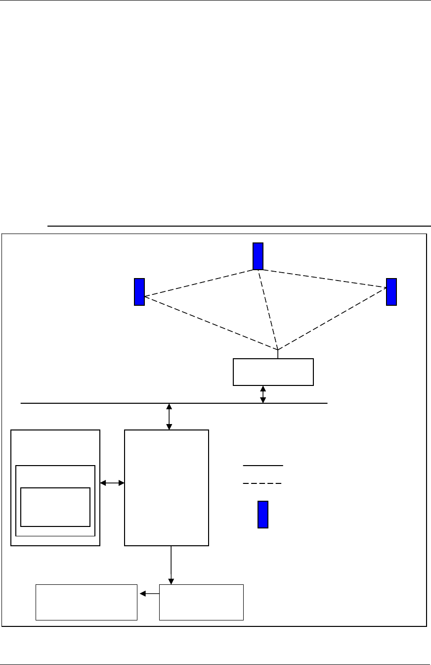
Figure 1. Diagram of the SKF Wireless Sensor Network.
HART Wireless
Gateway
LAN
Wired LAN
Wireless Network
SKF Wireless Machine
Condition Sensor
HCF OPC Server
or equivalent
server
DevCom2000
DD Host
DD library
CMWA 8800
DD
@ptitude Database @A OPC Client
OPC Link to save measurements
to @Analyst database

System Setup
System Setup
4 SKF Wireless Machine Condition Sensor Network
System Setup Guide
Hardware package checklist:
1 each: 24 VDC power supply for the WirelessHART gateway
1 each: Pepperl+Fuchs WirelessHART gateway (standard from the factory)
You may use a different gateway if the beta site already has an
existing WirelessHART network.
6 each: SKF Wireless Machine Condition Sensor
CD with HART OPC Server application, version 3.2.0; communicates with
wireless sensors through WirelessHART gateway
CD – SKF @ptitude Analyst 2010 Edition MR2

System Setup
How to set up the WirelessHART gateway
SKF Wireless Machine Condition Sensor Network 5
System Setup Guide
1 each: Product Beta CD containing:
– ProComSol DevCom2000 version 4.7D, HART software, communicates with
OPC Server
– SKF Wireless Machine Condition Sensor Device Descriptions file
– @ptitude Analyst with @ptitude Analyst OPC client
– Beta 1 System Setup Guide (this document)
– Pepperl+Fuchs WirelessHART gateway users manual
– Setting up an @ptitude Analyst / OPC connection Quick Start Guide
– PuTTY.exe Telnet client
General installation steps:
A. Set up the Pepperl+Fuchs WirelessHART gateway.
B. Configure the wireless sensors to join the network.
C. Install and configure the required software.
A. How to set up the WirelessHART gateway
For this first beta release, for new WirelessHART networks,
configure the sensors with the default network ID and join keys.
For sites with an established WirelessHART network, the sensors’
network ID and join keys must be preconfigured in the SKF factory.
SKF will add network ID and join key modification functions in later
beta releases.
1. For new networks, follow the instructions in the Pepperl+Fuchs gateway
user manual (section 3.6, Connecting to Power Supply and Grounding) to
connect the power supply to the gateway.
2. Follow instructions in the Pepperl+Fuchs user manual to connect an
Ethernet cable to the gateway’s Ethernet terminal, and connect the gateway
to the configuration computer (section 3.3, Connecting to Ethernet).
3. Follow section 4.4, Connecting via Ethernet, of the Pepperl+Fuchs user
manual to configure the computer to establish peer-to-peer connection
with the gateway.
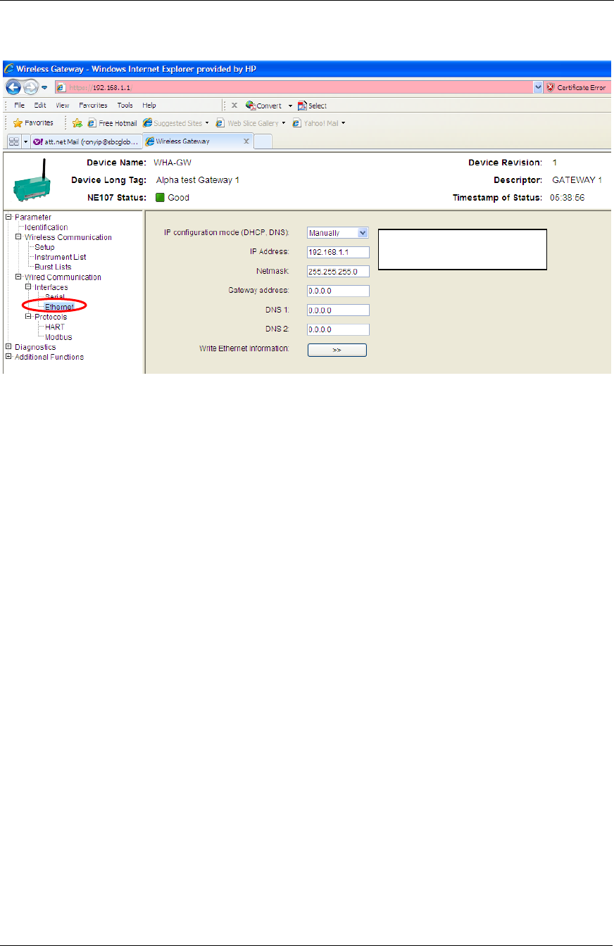
4. With the Ethernet cable connecting the gateway to the configuration
computer, use Windows Internet Explorer or an equivalent browser to set
up the LAN configuration as shown in the following figure. The default IP
address of the gateway is 192.168.1.1. Enter this IP address into your
browser’s address bar to access the Pepperl+Fuchs gateway’s configuration
web page and then modify the gateway’s IP Address and Netmask settings
to configure the gateway for your local area network.
The Pepperl+Fuchs gateway’s configuration web page resides inside
the gateway, not the internet.
System Setup
How to set up the WirelessHART gateway
6 SKF Wireless Machine Condition Sensor Network
System Setup Guide
Use the manually IP configuration mode setting to configure a static
IP address.
Figure 2. Setting up the Gateway LAN Configuration.
5. After setting your gateway’s IP Address and Netmask settings, press the
Write Ethernet Information button, confirm the prompt, and then press
OK. The gateway is now configured to communicate using your LAN.
6. Now you may disconnect the Ethernet cable from the configuration
computer and connect it directly to your LAN. After connecting the gateway
to LAN, on your configuration computer (which also connects to your LAN)
use your internet browser (reference step 4 above) to set up the
identification of the gateway as shown in the figure below. Reference the
Pepperl+Fuchs user manual for further details (section 5.3, Identification
Parameters).
Enter your LAN’s IP Address
and NetMask settings here.

System Setup
How to set up the WirelessHART gateway
SKF Wireless Machine Condition Sensor Network 7
System Setup Guide
Figure 3. Setting the Gateway’s Identification Parameters.
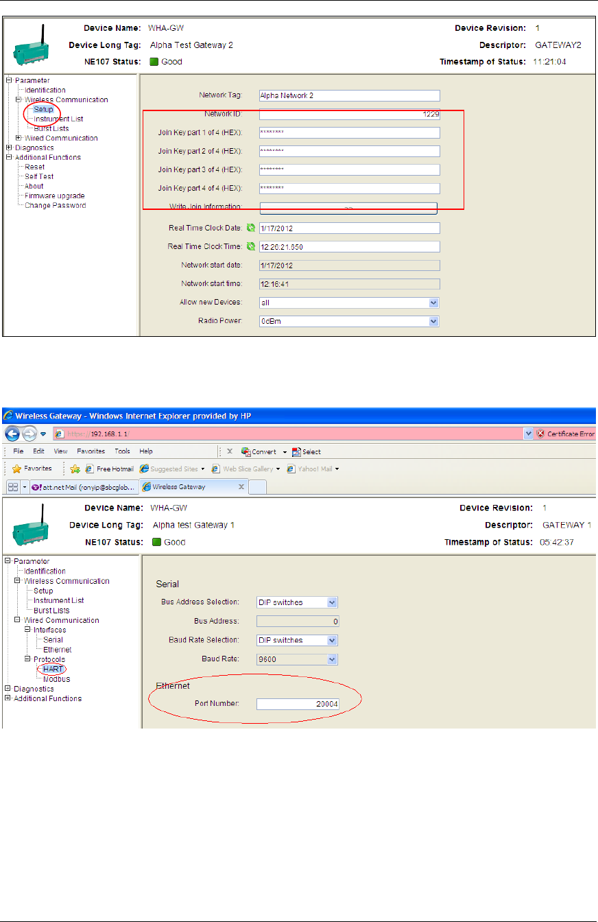
7. Next, set the gateway’s network ID to 1229 and join keys as shown in the
figure below. Reference the Pepperl+Fuchs user manual for further details
(section 5.4, Wireless Communication Parameters).
Join Key part 1 = 44555354
Join Key part 2 = 4E455457
Join Key part 3 = 4F524B53
Join Key part 4 = 524F434B
Before clicking the Write Join Information button, make sure the
eighth switch on the gateway’s DIP switch (inside the gateway) is
set to ON to allow writing the join information. Reference the
Pepperl+Fuchs gateway user manual (section 6.1.2, Buttons and
DIP Switches) for more information.
Press the Write Join Information button and confirm the prompts.
System Setup
How to set up the WirelessHART gateway
8 SKF Wireless Machine Condition Sensor Network
System Setup Guide
Figure 4. Setting the Gateway’s Network ID and Join Keys.
8. Set the gateway’s HART Ethernet port to 20004, as shown below.
Figure 5. Setting up HART Ethernet Port Number.
System Setup
How to configure the SKF Wireless Machine Condition Sensors to join the network
SKF Wireless Machine Condition Sensor Network 9
System Setup Guide
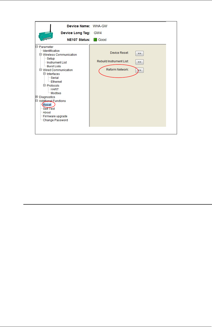
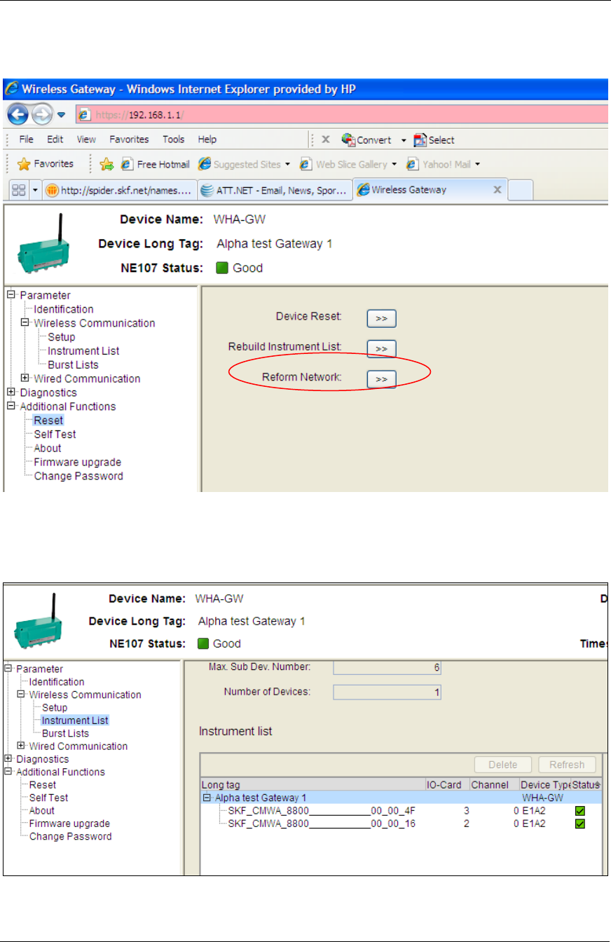
9. Your next step is to activate these new parameters in the gateway, as
shown in the figure below.
Figure 6. Activating New Parameters.
10. Press the Reform Network button to activate the new configuration.
At this time, leave the Pepperl+Fuchs gateway configuration web
page open, as you will need it for future steps. Proceed to the next
step: configuring the sensors to join the network.
B. How to configure the SKF Wireless Machine Condition Sensors to
join the network
1. Press the sensor’s button once to activate the sensor. You should see the
sensor LED flash progressively faster and then stop (approximately three
seconds), immediately followed by a short burst of quick flashes, which
indicates the command was acknowledged. The sensor is now activated
and ready to join the gateway in section A above.
If you need to deactivate the sensor, press the button and hold it for
four LED flashes. After releasing the button, you should see the
LED flash progressively slower until it completely stops, which
indicates the sensor is deactivated.
The sensor’s default network ID is 1229 from the factory, which
means it is ready to connect to the gateway as configured in the
previous section. The sensor has three optional network IDs from
the factory: 101, 102, and 1229. To reset it to the default 1229,
press the sensor’s button and hold it for nine LED flashes, then
release. After releasing the button, you should see a short burst of
quick flashes, which indicates the command was acknowledged.
System Setup
Software Setup Procedure
10 SKF Wireless Machine Condition Sensor Network
System Setup Guide
The sensor’s network ID is now set to 1229. Hold for seven flashes
to set to 101 or eight flashes to set to 102.
If you wish to reset the sensor, press and hold the button for three
LED flashes.
Repeat step 1 for each sensor.
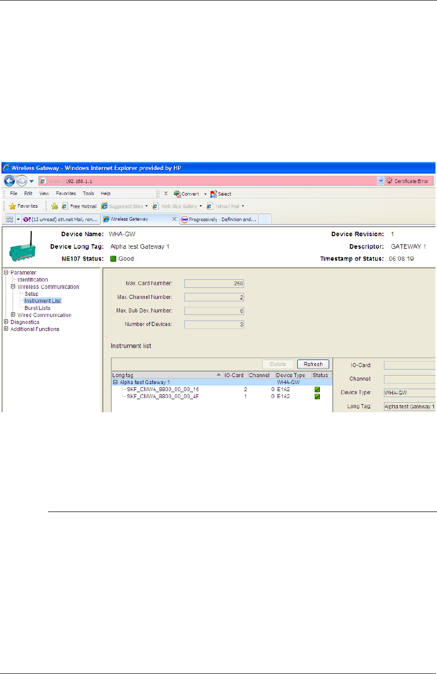
2. Your next step is to return to the Pepperl+Fuchs gateway configuration web
page, and using the Instrument List menu option, wait for the joining
process to complete for all the sensors. Depending on the number of
sensors, it may take up to ten minutes for all the sensors to appear in the
joining Instrument List, as shown in Figure 7.
Figure 7. Waiting for the Joining Process to Complete.
3. When all the sensors appear in the list and display a green checkbox in the
Status column, your WirelessHART network configuration is complete.
C. Software Setup Procedure
This section details how to install and configure multiple software applications and
utilities, including:
HART OPC Server, version 3.2.0
SKF Wireless Machine Condition Sensor Device Descriptions file (DD file)
ProComSol DevCom2000 version 4.7D
@ptitude Analyst
@ptitude Analyst OPC client

System Setup
Software Setup Procedure
SKF Wireless Machine Condition Sensor Network 11
System Setup Guide
Software Installation
This section guides you through the software installation process. After installing the
software, we will proceed to configure the software using the Software
Configuration section later in this guide.
Install all software on the @ptitude Analyst database server.
1. Install the HART Server version 3.2.0 – Insert the Hart Server CD into
your @ptitude Analyst database server’s CD drive. If the CD doesn’t autorun
automatically, start the installation by double clicking the setup.exe file on
the HART Server CD, and follow the onscreen instructions to complete
installation (accept all defaults). During the installation, you will need to
enter the registration key, which you can find on the CD case.
2. Install the ProComSol DevCom2000 version 4.7D – The beta CD provides
a ProComSol DevCom2000 User Manual.pdf in the DevCom2000_4_7D
folder. Locate this file and follow the instructions in section 4,
DevCom2000 Installation, to install the software (accept all default
settings). When it prompts you to select the activation type, either:
Evaluate the software
Activate manually
Activate online
Select the Activate the software online option, which requires the
computer to have internet access. The next dialog prompts you for a
License ID and Password. These have been previously emailed to you from
SKF USA Inc., San Diego. If you have not received your license ID and
password, contact ron.yip@skf.com.
If you do not have internet access, you may choose the Activate the
software manually option. After selecting this option, a dialog
provides you a User Code 1 and User Code 2. You must call,
email, or fax these user codes, along with the previously mentioned
License ID, to ProComSol (reference the ProComSol user manual
for contact information). ProComSol will respond with two
registration keys that you must enter to run the software.
3. Next, copy the SKF Wireless Machine Condition Sensor Device Descriptions
file (DD file) to the configuration computer. On the product CD, copy the
006052 folder located in the CMWA8800 DD folder to your computer’s
hard drive into the C:\HCF\DDL\Library folder.
4. Install the @ptitude Analyst software, if not already installed. Follow
instructions in the @ptitude Analyst Installation Manual located on the
@ptitude Analyst product CD.
5. Install the @ptitude Analyst OPC Client. Place the SKF Wireless Machine
Condition Sensor Product Beta CD in the @ptitude Analyst database server
computer and double click the setup.exe file located in the @A OPC Client
Manager folder. Follow the onscreen prompts (accept all defaults) to install
the software.
System Setup
Software Setup Procedure
12 SKF Wireless Machine Condition Sensor Network
System Setup Guide
Software Configuration
The general steps for configuring the various software applications are:
1. Import the wireless sensors into the WirelessHART Server application.
2. Configure the sensors using the DevCom2000 application.
3. Configure the @ptitude Analyst OPC client to link to the measurements in
the HART OPC Server.
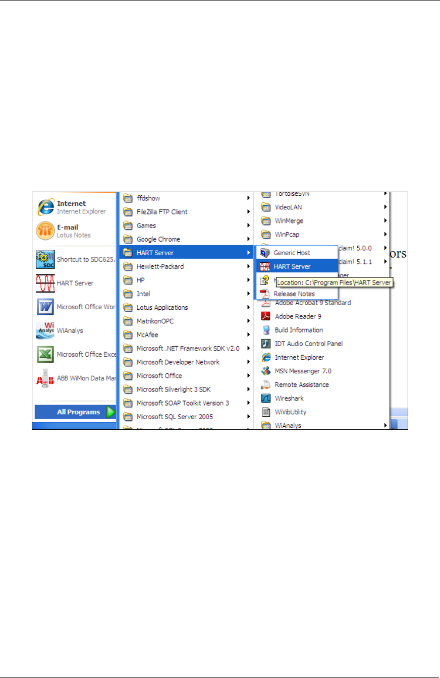
1. Import the SKF Wireless Sensors into HART OPC Server.
a) Launch the HART Server using Start/All Programs/HART Server.
The HARTServer.hoc – HART Server window opens.
Figure 8. Launching the HART Server.
System Setup
Software Setup Procedure
SKF Wireless Machine Condition Sensor Network 13
System Setup Guide
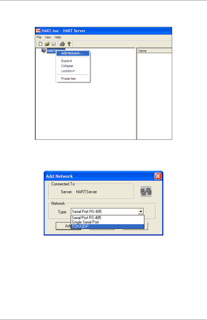
b) The first step is to add a new network to the HART Server. In the
left pane, right-click the HARTServer root node and select Add
Network.
Figure 9. Select Add Network.
c) An Add Network dialog opens. In the Network Type drop down
list, select the TCP/UDP option and click the Add button.
Figure 10. Add Network Dialog.
System Setup
Software Setup Procedure
14 SKF Wireless Machine Condition Sensor Network
System Setup Guide
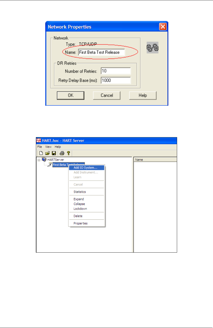
d) A Network Properties dialog opens. Enter a Network Name (e.g.,
“wireless sensor network”) and click the OK button.
Figure 11. Network Properties Dialog.
The new network appears under the HARTServer node in the left
pane.
Figure 12. Select Add IO System.
System Setup
Software Setup Procedure
SKF Wireless Machine Condition Sensor Network 15
System Setup Guide
e) Select the new network name and right-click it to Add IO System.
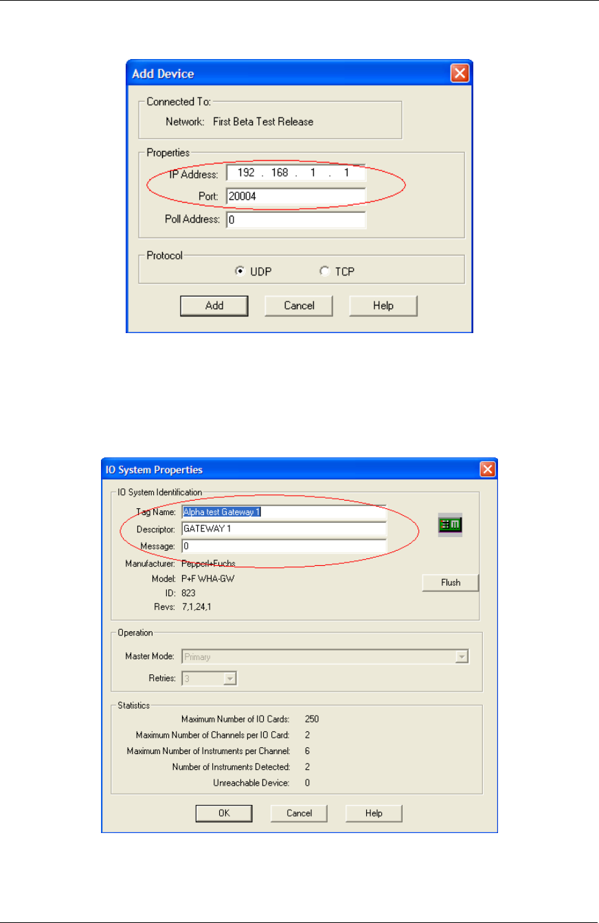
An Add Device dialog opens.
Figure 13. Add Device Dialog.
f) Enter the gateway’s IP Address and Port Address (as detailed
earlier in this document), and click the Add button to connect to the
gateway though the LAN connection. The IO System Properties
dialog appears and displays the gateway’s information.
Figure 14. IO Systems Properties Dialog.
System Setup
Software Setup Procedure
16 SKF Wireless Machine Condition Sensor Network
System Setup Guide
g) Click the OK button to complete the connection process. The newly
connected gateway now appears under the new network in the
HART Server dialog’s left pane.
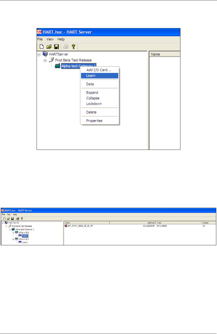
Figure 15. Select the Learn Option.
h) Select the new gateway and right-click the Learn option. After
selecting the Learn option, a confirmation prompt appears. Click
Yes and the gateway will then import all the sensors connected to
gateway (this will take a minute). As the import proceeds, the
hierarchy updates to show the gateway’s IO Card and wireless
sensor channel information.
Figure 16. HART Server Hierarchy.
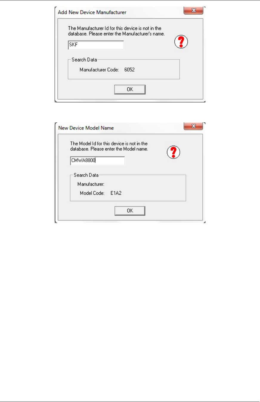
Note that when running the system for the first time, a dialog will
appear after the confirmation prompt asking for the manufacturer
name and the device model. Enter SKF for the manufacturer
name and CMWA8800 for the model name.
System Setup
Software Setup Procedure
SKF Wireless Machine Condition Sensor Network 17
System Setup Guide
Figure 17. Add New Device Manufacturer Dialog.
Figure 18. New Device Model Name Dialog.
i) After the import process is complete, you may select an IO card’s
channel (e.g., CH001) and the channel’s wireless sensor appears in
the right pane.

System Setup
Software Setup Procedure
18 SKF Wireless Machine Condition Sensor Network
System Setup Guide
j) At this point, the sensor import to the HARTServer process is
complete. Click File/Save to save the imported sensor setup (if you
select Save as, use the default file name: HART.doc).
Leave the HARTServer application open, as you will return to it later
in the setup process.
Figure 19. Save the Imported Sensor Setup.
You must now run a batch file to register the HART HSelect.dll file
with the Windows operating system. To do so, using Windows
Explorer, navigate to: c:\Program Files\ProComSol\Common\
RegisterSELECT.bat (for Windows XP applications) or
c:\Program Files\ProComSol\Common\RegisterSelect64.bat (for
Windows 7, 64-bit applications). Double click the .bat file to run it.
A success message appears; click OK and close Windows Explorer.
Important: Leave the HART.hoc HART Server application open
during the rest of the installation and during network operation
after installation.
Proceed to the next configuration step, configuring the sensors.
System Setup
Software Setup Procedure
SKF Wireless Machine Condition Sensor Network 19
System Setup Guide
2. Configure the SKF Wireless Sensors in DevCom2000.
The next procedure will detail how to configure identification settings and
sensor update settings for the wireless sensors.
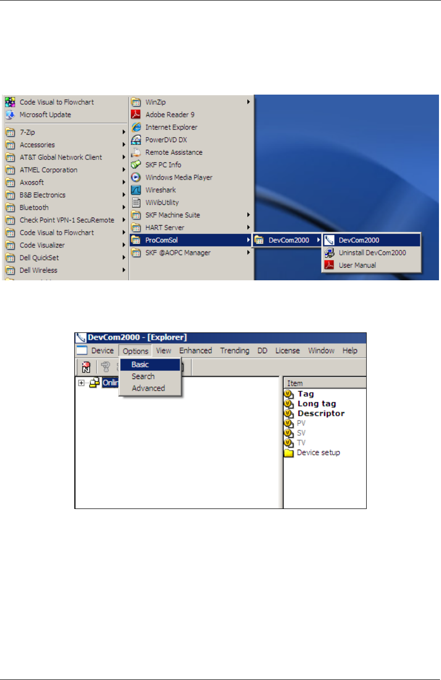
a) Use Windows’ Start/All Programs/ProComSol/DevCom2000 to
launch the application, as shown below.
Figure 20. Launch the Application.
The DevCom2000 widow displays.
Figure 21. DevCom2000 Window.
b) When the DevCom2000 launches the first time, it displays a
warning dialog about not being able to connect to a serial port.
Simply dismiss the dialog, as we are not using a serial port.
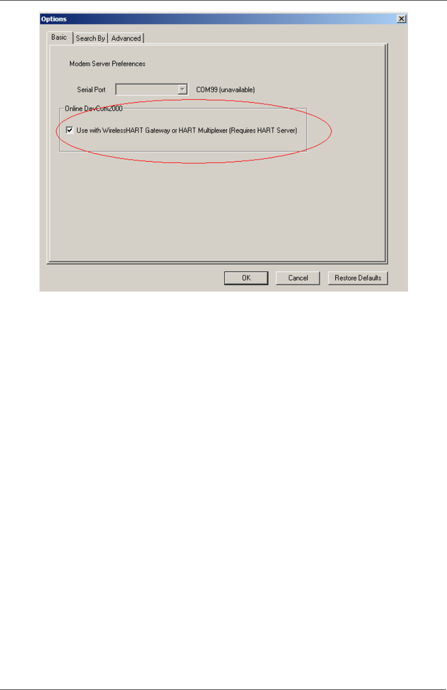
c) Configure the software to connect using the HART Server. To do
so, select the Options/Basic menu option as shown above. The
Options dialog displays.
System Setup
Software Setup Procedure
20 SKF Wireless Machine Condition Sensor Network
System Setup Guide
Figure 22. Options Dialog.
d) Enable the Use the WirelessHART Gateway or HART Multiplexer
(Requires HART Server) checkbox, click the OK button, and press
Yes at the confirmation prompt. A dialog informs you that your
preferences are saved; press OK. The DevCom2000 window
remains empty.
e) The wireless setting is not effective until DevCom2000 is exited
and re-launched. Exit and re-launch DevCom2000.
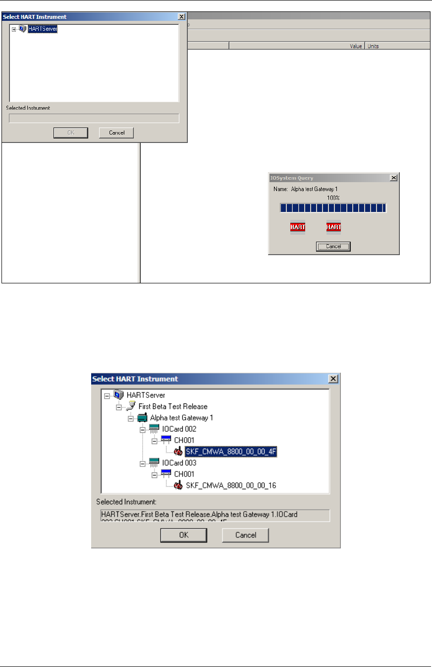
f) When DevCom2000 is re-launched, it will automatically launch the
HART Server application to connect to the gateway.
System Setup
Software Setup Procedure
SKF Wireless Machine Condition Sensor Network 21
System Setup Guide
Figure 23. Launching the HART Server Application.
g) DevCom2000 now provides a Select HART Instrument view
window (upper left) that allows you to select connected wireless
sensors to configure. In the Select HART Instrument view
window, all previously connected sensors should display.
Figure 24. Select HART Instrument Window.
At this time, ignore the Reading device information, Please wait…
prompt in the DevCom2000 window.

System Setup
Software Setup Procedure
22 SKF Wireless Machine Condition Sensor Network
System Setup Guide
h) Select a sensor from the Select HART Instrument list and press
the OK button. The software will start uploading data from the
sensor and the window will update (this will take a minute).
Figure 25. Device Status Window.
i) When the software connects to the sensor, a Device Status dialog
informs you that modifications have been made. Press ALL to
suppress all future similar messages. You return to the
DevCom2000 Window’s main view showing the sensor’s
identification. DevCom2000 uses the DD file to display
configuration data for the selected sensor.
Figure 26. DevCom2000 Window with Sensor Identification Information.
j) With the Online hierarchy item selected, the sensor’s identification
information and the sensor’s three measurements results display in
the right pane. The Primary Value (PV) is the overall velocity in
mm/s. The Secondary Value (SV) is the overall Acceleration
Enveloped measurement in mm/s squared, and the Tertiary Value
(TV) is the temperature in degrees Celsius.
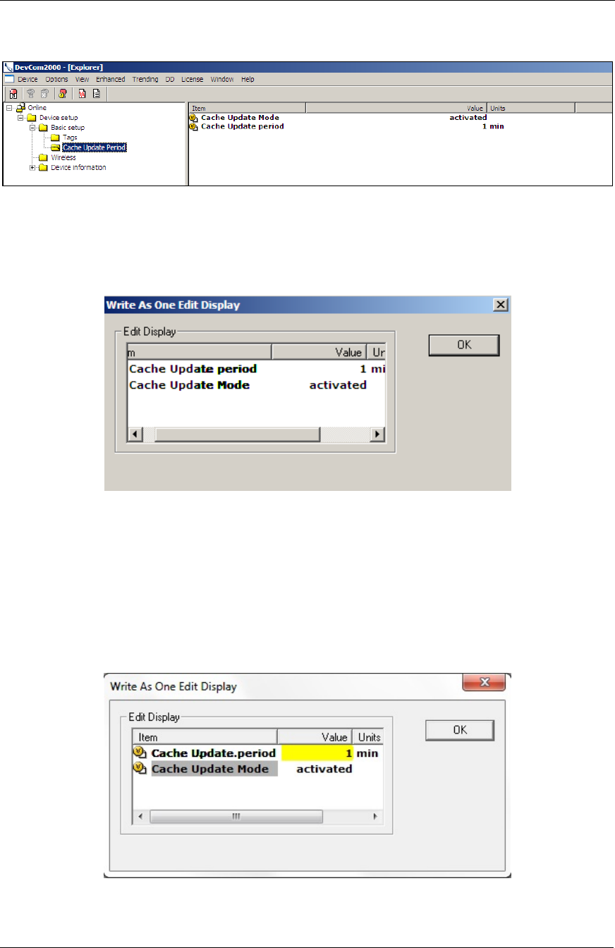
k) The next task is to configure the data collection interval for the
sensor (i.e., how often the sensor refreshes its measurement
results inside the sensor); the default is 720 minutes, or every 12
hours. To configure this, select the Basic Setup/Cache Update
System Setup
Software Setup Procedure
SKF Wireless Machine Condition Sensor Network 23
System Setup Guide
Period option from the left pane. The right pane updates to show
the current settings.
Figure 27. DevCom2000 Window, Cache Update Period Selected.
l) From the right pane, double click the Cache Update period option
to display the Write As One Edit Display dialog (both settings are
always updated to the sensor).
Figure 28. Write As One Edit Display Dialog.
m) In the Item column, double click the Cache Update period item; a
Cache Update period dialog displays. Set the time interval in
minutes to one half the setting for @ptitude Analyst measurement
updates (set in step 3.g later in this document). We recommend no
more than 12 measurements per day (one measurement every
two hours) for battery conservation, in which case the update
period should be set to 60 minutes. Click Set to proceed.
Figure 29. Write As One Edit Display Dialog.

System Setup
Software Setup Procedure
24 SKF Wireless Machine Condition Sensor Network
System Setup Guide
n) Back in the Cache Write As One Edit Display dialog, the
background color of the modified setting changes to yellow to
indicate that the setting has been modified, but the modification
has not been sent to the sensor. Click OK to exit the dialog. You
return to the main view window, where the Cache Update period
setting is also highlighted to indicate the new setting needs to be
sent to the sensor.
Figure 30. Main View Window with Cache Update Period Setting Highlighted.
o) In the toolbar, select the Send to device button to send the new
Cache Update settings to the sensor. When the highlight
disappears, the setting is stored in the sensor.
Figure 31. Send Cache Update Settings to the Sensor.
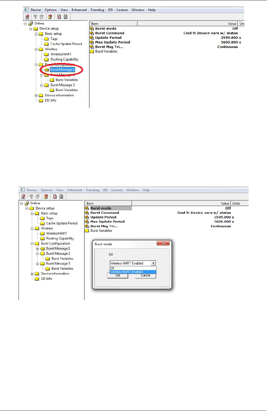
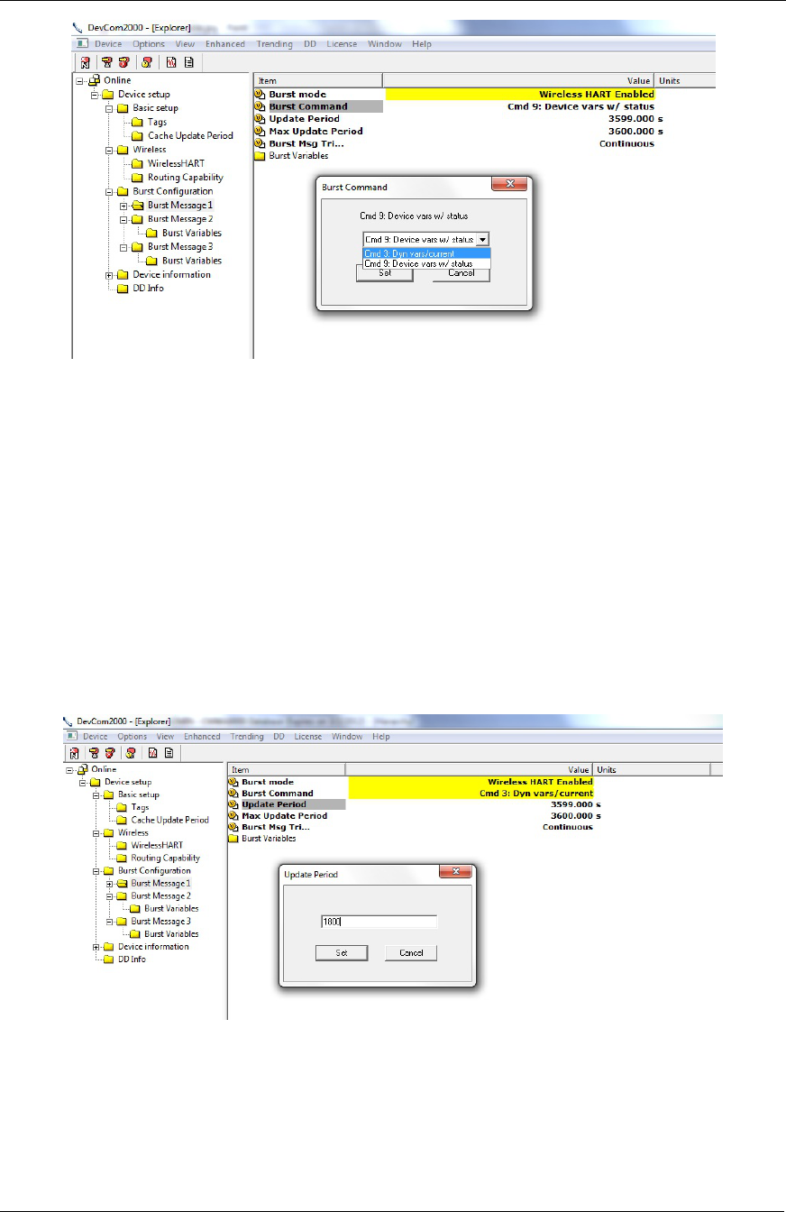
p) The next task is to enable the Burst mode setting to burst the
response for the Cmd 3: Dyn vars / current query. Burst mode is
a special HART communication mode in which the sensor sends the
response of a query at a preprogrammed interval to the gateway,
without being polled. This reduces network traffic and stress on
the sensor firmware. When burst mode is enabled for Cmd 3, the
sensor sends overall velocity, acceleration enveloping, and
temperature measurements to the gateway at regular time
intervals, eliminating the need for the gateway to poll the sensor
each time the HART OPC server sends the Cmd 3 query. To
configure the burst mode, select the Burst Configuration / Burst
Message1 option from the left pane. The right pane updates to
show the current settings.
System Setup
Software Setup Procedure
SKF Wireless Machine Condition Sensor Network 25
System Setup Guide
Figure 32. Burst Configuration Window, Burst Message1 Selected.
q) In the right pane, double-click the Burst Mode item to display the
Burst Mode dialog. On the Burst Mode dialog, select the Wireless
HART Enabled option from the drop-down list and click Set to
enable the setting and return to the main view window. The
background color of the modified setting changes to yellow to
indicate that the setting has been modified, but the modification
has not been sent to the sensor.
Figure 33. Enable the Burst Mode Setting.
r) Double-click the Burst Command item on the right pane. The
Burst Command dialog displays. Select the Cmd 3: Dyn
vars/current option from the drop-down list. Click Set to save the
setting and return to the main view window. Again, the
background color changes to yellow.
System Setup
Software Setup Procedure
26 SKF Wireless Machine Condition Sensor Network
System Setup Guide
Figure 34. Select the Cmd 3: Dyn vars/current Burst Command Option.
s) Double-click the Update Period item to set the interval period for
how often the sensor will send its measurement data to the
gateway. The recommended burst update period is half of the
cache updated period set in step m, above. If the cache updated
period is set to 60 minutes, the recommended burst update period
is 30 minutes (1800 seconds). Click Set to save the setting and
return to the main view window. The background color changes to
yellow.
The Update Period value must always be less than the
Max Update Period value. The sensor must send data to
the gateway at least once before the Max Update Period
expires.
Figure 35. Enter the Update Period Interval.
t) In the toolbar, select the Send to device button to send the new
Burst Message1 settings to the sensor. When the highlight
disappears, the setting is stored in the sensor. You may confirm
that the burst mode is working on the gateway’s Burst Lists web

System Setup
Software Setup Procedure
SKF Wireless Machine Condition Sensor Network 27
System Setup Guide
page. The first burst packet should appear in the Burst Lists after
the specified update period elapses.
Figure 36. Send Burst Message1 Settings to the Sensor.
u) The sensor’s Tag, Long Tag, and Descriptor settings are initially
set to factory defaults. You may use the Basic setup/Tags option
to modify these settings in a manner similar to the Cache Update
period setting. Note that the Long tag setting initially displays the
sensor’s MAC address at the end of the tag (e.g., 00_00_4A). This
is useful information, so it is best to leave this as is. However, you
may wish to modify the Descriptor setting to identify the sensor’s
location, orientation, etc.
v) Repeat steps j through u for all connected sensors. To easily do so,
select the Device/New Device menu option. The Select HART
Instrument list appears, where you may select a different IO
card/channel/sensor whose settings you wish to modify.
System Setup
Software Setup Procedure
28 SKF Wireless Machine Condition Sensor Network
System Setup Guide
3. Configure the @ptitude Analyst OPC client to link to the measurements
in the HART OPC Server.
a) On the Product Beta CD, in the @A OPC Client Manager folder is
the QUICK START - SETTING UP AN @PTITUDE ANALYST - OPC
CONNECTION.DOC document. Open this document and follow the
five steps detailed in section 1.4, Prepare the @ptitude Analyst
database, to manually create the MAOPCMGR and MAOPCSRV
users in @ptitude Analyst. Note: The MAOPC_Create_Users.sql
script file does not work.
b) Next, From Windows’ Start menu, select Start/All Programs/SKF
@AOPC Manager/@A OPC Manager to launch the SKF @A OPC
Manager - @AOPC software.
c) In the same document, follow the instructions in section 1.5.1,
@A Database connection, to establish the @A database
connection as the OPC client.
Figure 32. Establish a Connection as the OPC Client.
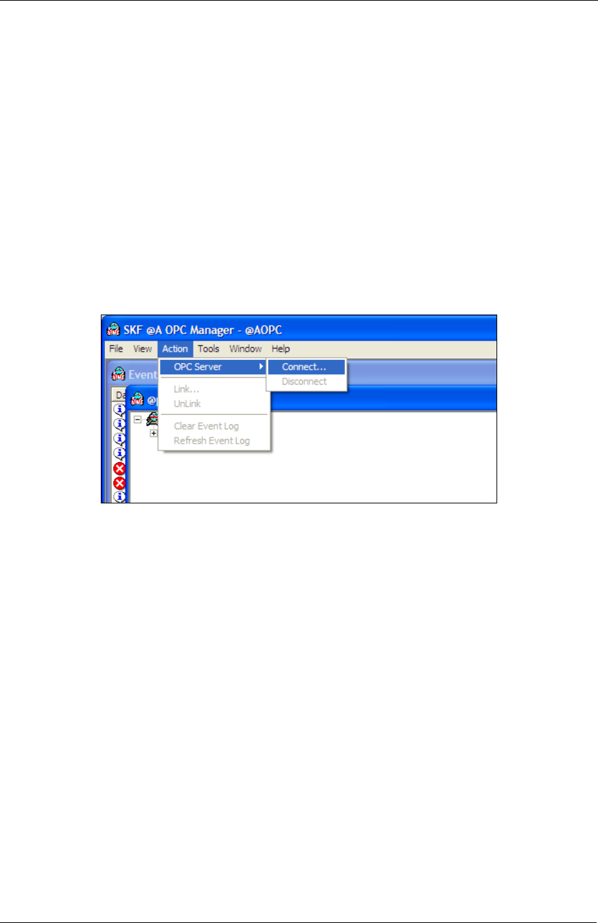
d) The following steps show how to connect the @AOPC manager to
the HART OPC server.
i. In the SKF @A OPC Manager application, select the
Action/OPC Server/Connect menu option to view a list of
servers in your LAN. The OPC Connection Settings dialog
opens.
System Setup
Software Setup Procedure
SKF Wireless Machine Condition Sensor Network 29
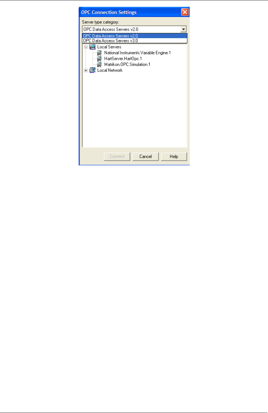
System Setup Guide
Figure 33. OPC Connection Settings Dialog.
ii. In the Server type category drop down list, select the OPC
Data Access Servers v2.0 option to display the
HartServer.HartOpc.1 HART OPC server in the list of Local
Servers.
iii. Select the HartServer.HartOpc.1 server, and press the
Connect button to complete the connection to the HART OPC
server. You return to the OPC Manager’s main view.
e) The following steps set up the link to import the measurements
from one SKF Wireless Machine Condition Sensor to the @ptitude
Analyst database through the connection to HART OPC Server.
i. Open @ptitude Analyst.
ii. Create a new hierarchy for the wireless sensors (e.g., SKF
Wireless Machine Condition Sensor database).
iii. In the new hierarchy, create a new Machine hierarchy item
for each sensor (e.g., T1FeedPumpDS).
System Setup
Software Setup Procedure
30 SKF Wireless Machine Condition Sensor Network
System Setup Guide
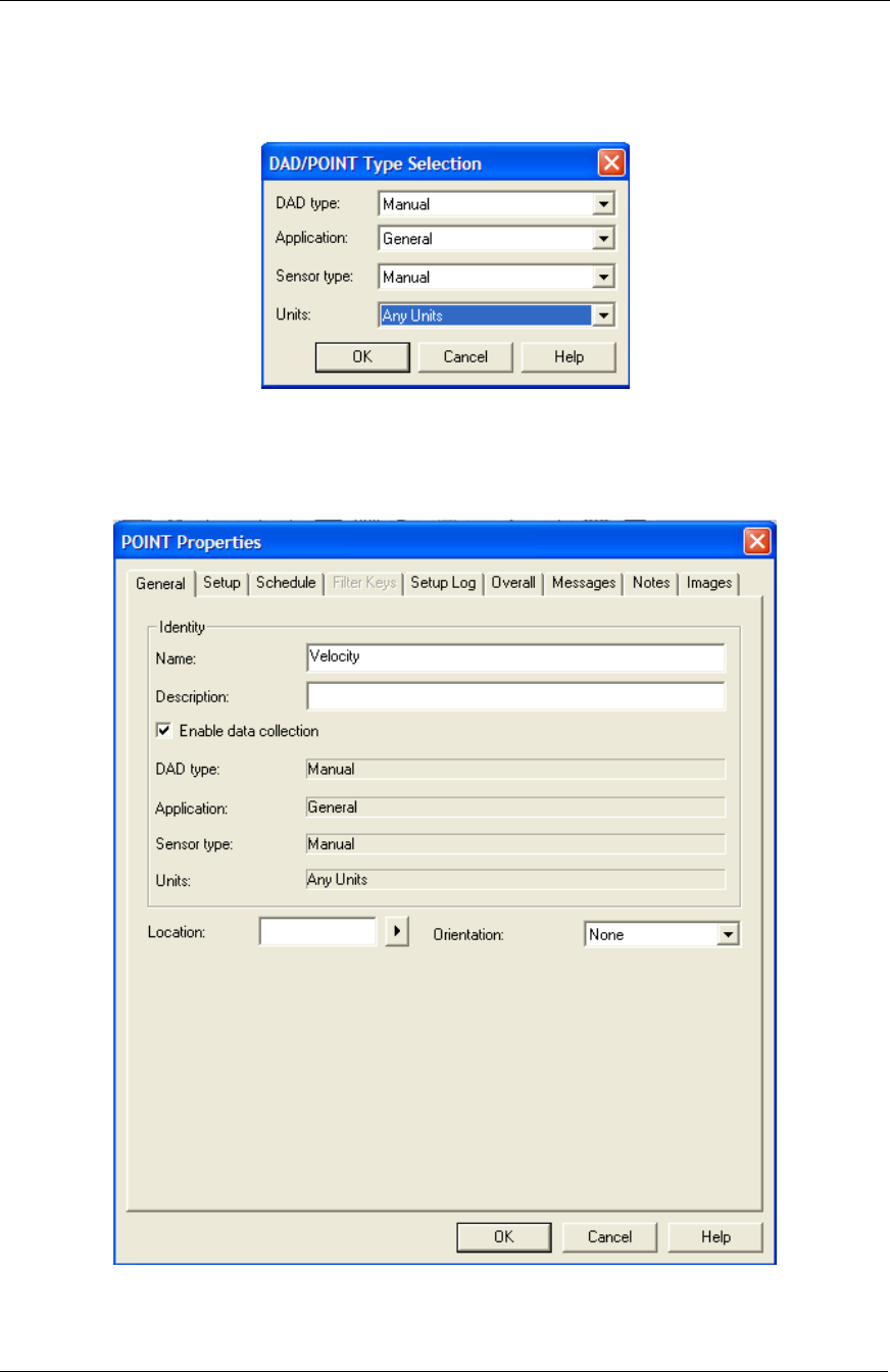
iv. For each new Machine (sensor) hierarchy item, create three
Manual type POINTs, one for each sensor measurement
(velocity, enveloped acceleration, and temperature) as
detailed in the figures below.
Figure 34. DAD/POINT Type Selection Window.
v. Use the POINT Properties/General tab to name each new
POINT with a descriptive name.
Figure 35. POINT Properties Window, General Tab.
System Setup
Software Setup Procedure
SKF Wireless Machine Condition Sensor Network 31
System Setup Guide
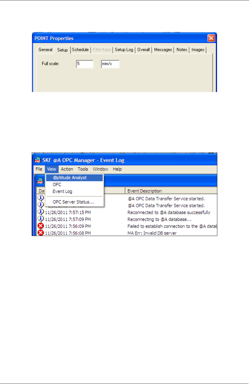
vi. Use the POINT Properties/Setup tab to modify the new
POINT’s units to mm/s, m/s^2 or C for three respective
POINTs.
Figure 36. POINT Properties Window, Setup Tab.
POINT Properties/Schedule settings are not applicable for wireless
sensor networks.
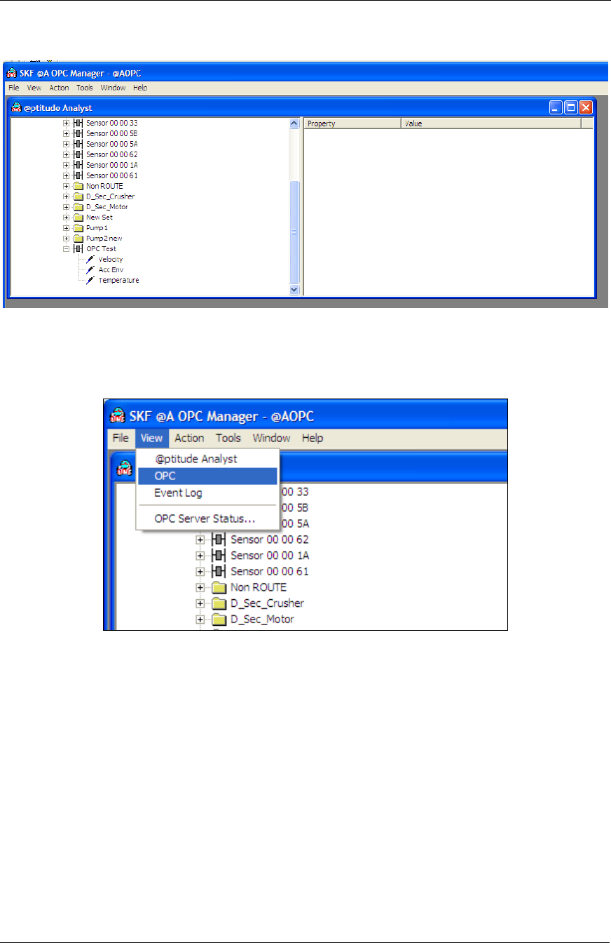
vii. Back in the SKF @AOPC Manager - @ptitude Analyst
application, select the View/@ptitude Analyst menu option
to open the @ptitude Analyst hierarchy window.
Figure 37. SKF @A OPC Manager Window, View @ptitude Analyst.
System Setup
Software Setup Procedure
32 SKF Wireless Machine Condition Sensor Network
System Setup Guide
viii. Open the Analyst hierarchy to show the newly created
Velocity, Acc Env and Temperature points.
Figure 38. @ptitude Analyst Hierarchy.
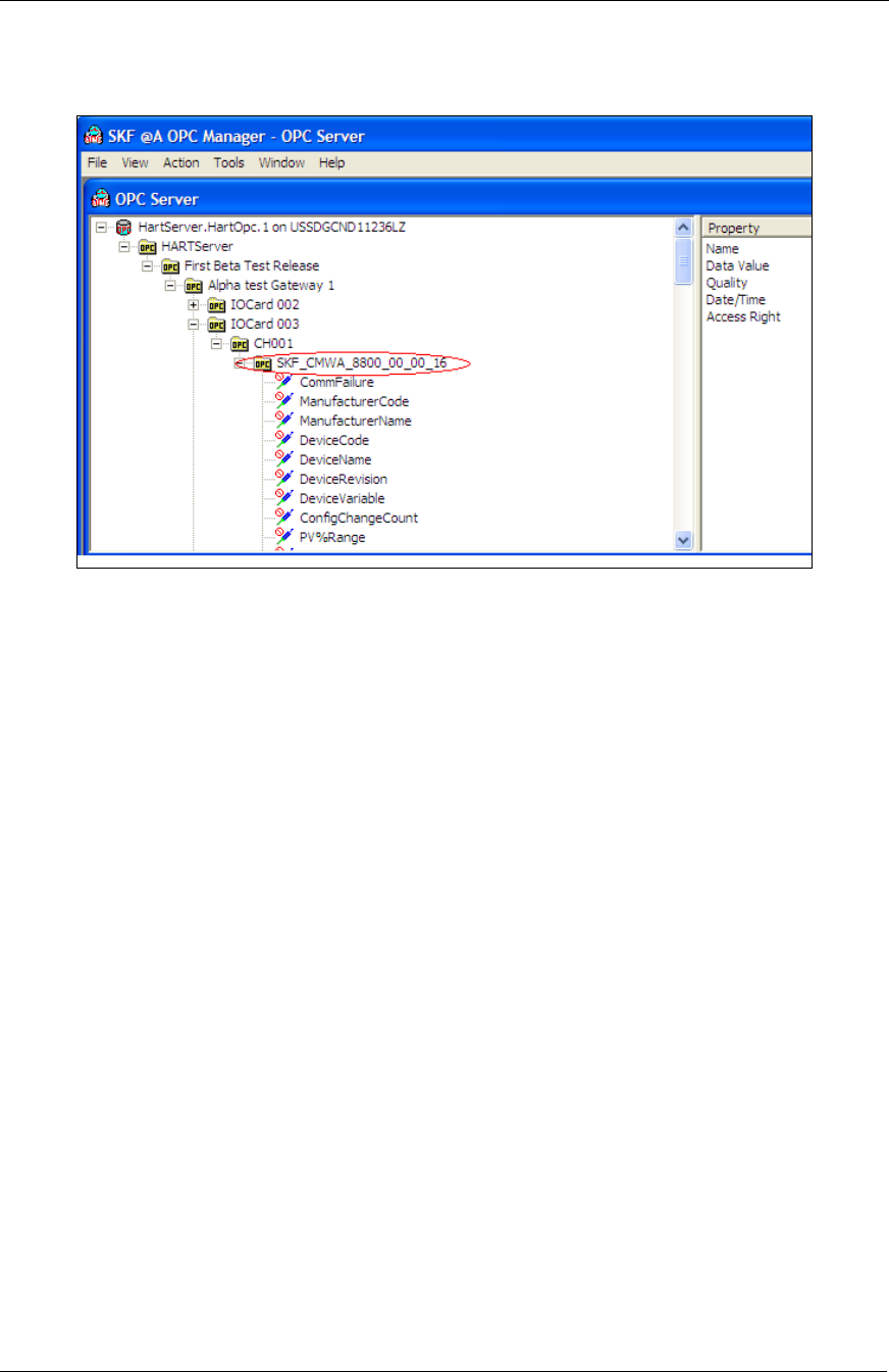
ix. Next, in @AOPC Manager, select the View/OPC menu option
to open the HART OPC Server window.
Figure 39. SKF @A OPC Manager Window, View OPC.
System Setup
Software Setup Procedure
SKF Wireless Machine Condition Sensor Network 33
System Setup Guide
x. In the OPC Server window, open the HartServer.HartOpc.1
server’s hierarchy and double click to open the sensor for
which you would like to create a link.
Figure 40. Open Sensor to Create a Link.
xi. To simplify the display for the two open windows (the OPC
Server window and the @ptitude Analyst window), select
the Windows/Tile Horizontal menu option to tile the two
windows.
System Setup
Software Setup Procedure
34 SKF Wireless Machine Condition Sensor Network
System Setup Guide
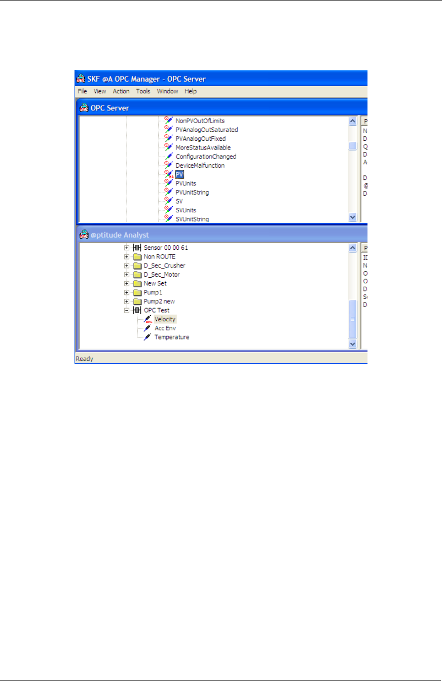
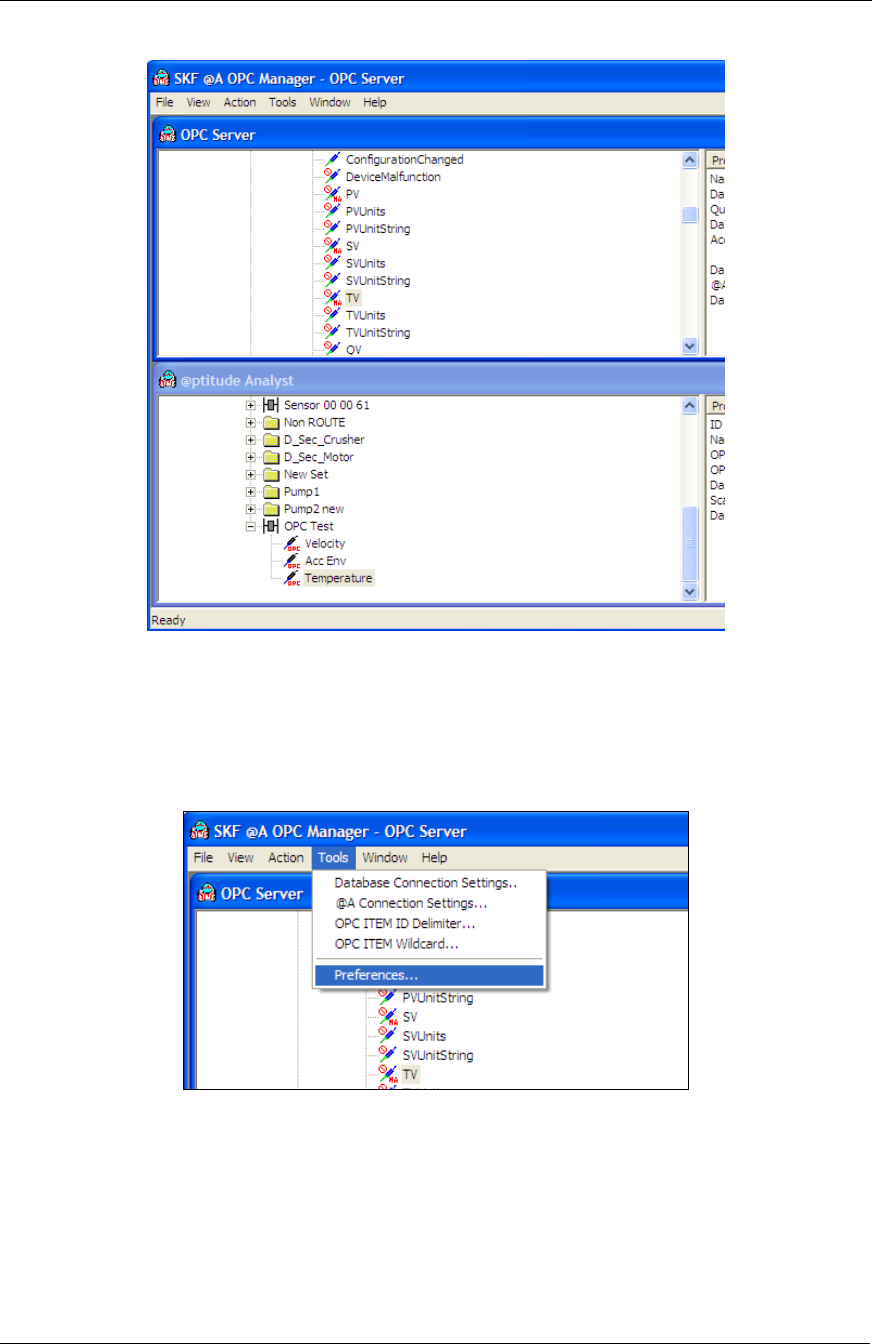
xii. Next, in the OPC Server window, for the open sensor, select
the PV hierarchy item and drag it to the same sensor’s
(machine hierarchy item) velocity POINT in the @ptitude
Analyst window to create the link.
Figure 41. Select PV Hierarchy Item.
xiii. Repeat this process to link the SV hierarchy item to the
sensor’s Env. Acc. POINT and the TV item to the sensor’s
temperature POINT. Now, for the selected sensor, all three
measurements link to the @ptitude Analyst database.
Hierarchy icons for the linked items update to display they are
linked; i.e., in the OPC Server window, the hierarchy items
show an MA icon (Machine Analyst), and in the @ptitude
Analyst window, the hierarchy items show an OPC icon.
System Setup
Software Setup Procedure
SKF Wireless Machine Condition Sensor Network 35
System Setup Guide
Repeat the above process for all the other sensors.
Figure 42. Repeat Process for Other Sensors.
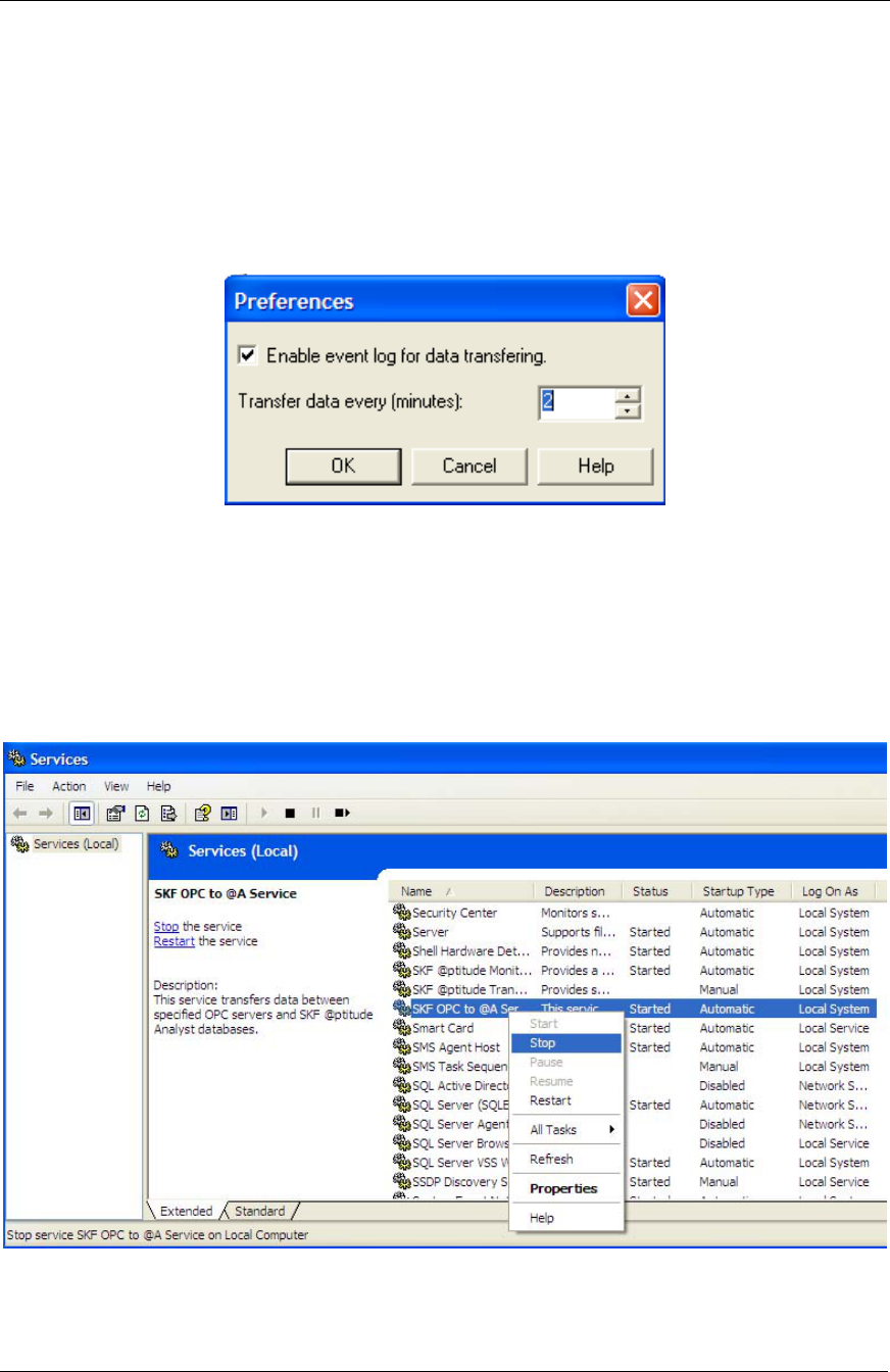
f) The remaining task is to configure the time interval at which the
OPC Server will update measurement results in @ptitude Analyst.
To do this, in the @AOPC Manager application, select the
Tools/Preferences menu option. The Preferences dialog displays.
Figure 43. Select Tools/Preferences.
System Setup
Software Setup Procedure
36 SKF Wireless Machine Condition Sensor Network
System Setup Guide
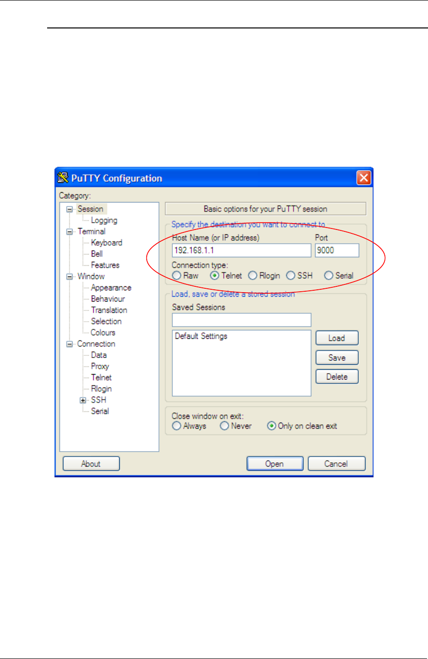
g) In the Transfer data every field, set the time interval in minutes at
which the OPC Server updates the linked measurements in
@ptitude Analyst. The setting should be at least twice the Cache
Update period setting in the sensor (previously discussed in step
2.m above) to avoid sending stale measurements to @ptitude
Analyst. We recommend no more than 12 measurements per day
(one measurement every two hours) for battery conservation. For
example, set to 120 minutes for measurement every two hours.
Click OK to accept the new transfer period.
Figure 44. Preferences Dialog.
h) Note that the @Analyst OPC client does not work when run as a
Windows service. Therefore, you must stop the “SKF OPC to @A
Service” in the Windows Services manager. To do so, in the
Windows Control Panel, select Administrative Tools, then select
Services, then right-click the SKF OPC to @A Service, and select
Stop.
Figure 45. Stop the SKF OPC to @A Service.

System Setup
Regular Operation
SKF Wireless Machine Condition Sensor Network 37
System Setup Guide
i) Next, you need to launch the MAopcSrv.exe to run as process.
Using Windows Explorer, open the Program Files/SKF/
MAOPCMGR folder and double click the MAopcSrv.exe file. A
waiting indicator briefly appears.
Figure 46. Launch MAopcSrv.exe to Run as Process.
j) Once the @A OPC Data Transfer Service is started, the HART OPC
Server initiates and proceeds to send measurement results to
@ptitude Analyst according to the previously set transfer data
period.
The software configuration is now complete.
Regular Operation
At the end of step 1, we stated that you need to leave the HART.hoc HART Server
application open during the rest of the installation and during network operation
after installation. This application and the MAopcServer.exe running as a process
(detailed above) are the only two applications required to be running to collect
measurements for regular wireless sensor operation.

System Setup
Troubleshooting
38 SKF Wireless Machine Condition Sensor Network
System Setup Guide
Troubleshooting
If new measurements are not updating to @ptitude Analyst, check the following:
Confirm the sensor is currently connected using the gateway’s Instrument List
web page.
In the Windows Task Manager, confirm the MAopcSrv.exe is running as a
process. If not, launch MAopcSrv.exe in C:\Program Files\SKF\MAOPCMGR
as detailed above. In the Windows Services, verify that MAopcSrv.exe is not
running as a service.
In the Windows Task Manager, confirm that Hartopc.exe is running. If not,
launch C:\Program Files\HART Server\Hartopc.exe.
Verify the OPC link using the @AOPC Manager.
Known Bugs
The SKF @AOPC client does not work as a windows service. The work around
is to launch it as a process.
The sensor LED may stop responding if, by press of the button, selecting the
reset command is immediately followed by selecting the shutdown command.
The work around is to wait at least 30 seconds between the reset and a shut
down.
Recovery Process
After a shut down, follow this procedure to restart the system:
Power up the gateway.
Turn on all sensors.
Power up the computer running the HART OPC Server and OPC client.
In the gateway’s web page, verify all sensors are connected.
Launch DevCom2000 to verify connection to the sensors. This step will
automatically launch the HART OPC server.
Stop @A OPC client running as a service and restart running as a process by
launching MAOPCSrv.exe manually.
Launch @Analyst to verify the system resumed collecting measurements.
System Setup
Configuring the Network ID
SKF Wireless Machine Condition Sensor Network 39
System Setup Guide
Configuring the Network ID
The WirelessHART protocol allows only the network manager to modify the field
device’s network ID. Any attempt to change the network ID by a non-network
manager will result in getting an “Access Restricted” error code returned by the field
device.
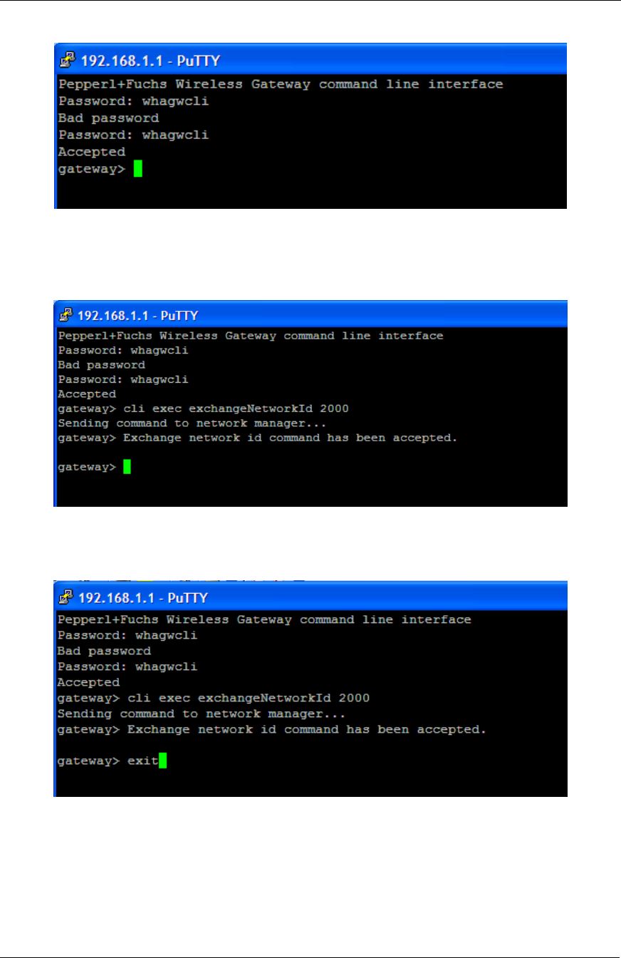
In order to change the network ID in this first beta release, the user must use the
free telnet client, PuTTY.exe, to send the command through the CLI of the network
manager in the Pepperl+Fuchs gateway. You will find the PuTTY.exe file in the first
Beta release CD. Use the WirelessHART gateway IP address and Port 9000 to
connect to the CLI as a Telnet client, as shown below.
Figure 47. PuTTY Configuration Window.
System Setup
Configuring the Network ID
40 SKF Wireless Machine Condition Sensor Network
System Setup Guide
Once connected, enter the password, whagwcli, twice to log in.
Figure 48. PuTTY Password Prompt.
Enter cli exec exchangeNetworkId xxx to modify the network ID of all field devices
connecting to the gateway, where xxx is the new network ID.
Figure 49. PuTTY Gateway Prompt.
Enter exit to terminate the Telnet client program.
Figure 50. Terminate the Telnet Client Program.
System Setup
Configuring the Network ID
SKF Wireless Machine Condition Sensor Network 41
System Setup Guide
For a beta network using six to ten SKF Wireless Machine Condition Sensor units,
wait 15 minutes after sending the command before activating the new network ID by
reforming the network.
Figure 51. Reform the Network.
Verify that all SKF Wireless Sensors are reconnecting after the network ID change in
the Instrument List web page.
Figure 52. Instrument List Page.

SKF Wireless Machine Condition Sensor Network 1
System Setup Guide
Installation of the SKF Wireless Machine Condition
Sensor
WARNING! Your safety is extremely important. Read and follow all
warnings in this document before handling and operating the equipment. You
can be seriously injured, and equipment and data can be damaged if you do not
follow the safety warnings. Refer to the beginning of this guide for important
safety messages.
Installation in Hazardous Locations
The SKF Wireless Machine Condition Sensor is certified for installation in safe areas,
and in ATEX Zone 0, 1, and 2 areas.
SKF Wireless Machine Condition Sensor Dimensions
The following features allow easy mounting and un-mounting of the SKF Wireless
Sensor:
Standard 1/4-28 UNF mounting hole threading
Robust metal base for applying mounting torque with 33.34 mm wrench
You can also access the SKF Wireless Sensor nut from top with a 100 mm long
socket wrench. See the figure below for sensor dimension details.
Error! Objects cannot be created from editing field codes.
Figure 53. SKF Wireless Machine Condition Sensor Main Dimensions.
Mounting Requirements
WARNING! Request a work permit from the site responsible Safety Officer
prior to commencing any installation work. Drilling is not allowed in ATEX Zone
0, 1, and 2 areas. Magnetic or adhesive mounting pads may be allowed.
The mounting configuration depends upon the dynamic measurement requirements,
such as frequency and amplitude range. Other factors to consider are mounting
location, prohibitions, accessibility, and temperature. In general, there are three
mounting configurations:
Magnets
Adhesives
Threaded studs

Installation of the SKF Wireless Machine Condition Sensor
Mounting Requirements
2 SKF Wireless Machine Condition Sensor Network
System Setup Guide
The mounting method affects the frequency range that can be measured; the less
rigid the method, the lower the maximum frequency.
Magnetic Mounting
Magnetic mounts are also popular in walk-around monitoring programs and the
frequency response is better, although still dramatically reduced when compared to
stud or adhesive mounts.
Magnetic mounts are available with flat surfaces for flat locations or two pole
configurations for curved surfaces. Ensuring the magnet is firmly attached is vital for
good measurements.
Adhesive Mounting
If you cannot tap a hole properly into the machine, an adhesive mount is
recommended. The rigidity of an adhesive mount is very dependent on the suitability
of the adhesive used for the environment and whether it has been applied in
accordance to the manufacturer’s instructions. The SKF Wireless Sensor wireless
condition monitoring node needs to be grounded to the machine; therefore, a
conductive adhesive must be used.
Mounting Pads
When using an adhesive, you may directly attach the sensor to the machine or onto
an adhesive mounting pad. Use of an adhesive mounting pad is recommended if
repeated removal of the sensor is required. After the pad is adhered to the machine,
the sensor is torqued onto the stud. Apply a coupling fluid to the stud face that
mates with the sensor.
The sensor case must be grounded to the machine and the installer
must ensure that the adhesive mounting pad is electrically
grounded to the machine.
Threaded Studs
The use of stud mounting results in the widest frequency measurement range. It is
recommended for permanent monitoring systems, high frequency testing, and harsh
environments.
The mounting point on the structure should be spot-faced to 1 in. diameter; the
mounting face of the sensor is 24 mm (0.945 in.) in diameter. The surface should
be flat within 25 μm (0.001 in.) and have surface texture no greater than 0.8 μm (32
μin.). The tapped hole must be perpendicular to the mounting surface and at least
two threads deeper than the stud. This will prevent a gap between the sensor and
the mounting surface, and produce optimum frequency response.
Proper screw torque on the mounting stud is also required. Under-torque of the
sensor reduces the stiffness of the coupling. Over-torque can cause permanent
thread damage to the sensor.
It is recommended to use a thread adhesive such as Loctite 222.

Installation of the SKF Wireless Machine Condition Sensor
Mounting Requirements
SKF Wireless Machine Condition Sensor Network 3
System Setup Guide
Pipe Thread Adapters
Pipe thread mounting adapters provide a mounting location for either magnetically
mounted or permanently mounted sensors, but avoid the need to drill a hole in the
machine and spot-face. They can make use of existing plugged holes on the
machine.
Securing the SKF Wireless Sensor to the Machine Surface
You must mount the SKF Wireless Sensor so that it is grounded to the machine. If
using mounting pads that are adhesively mounted onto a machine, then the adhesive
used must be conductive. If a coupling fluid is used between the machine or
mounting pad and the sensor, then we recommend the fluid to be conductive (even
though the stud itself will make an electrical coupling to the machine or mounting
pad).
Mounting Torque
Recommended SKF Wireless Machine Condition Sensor mounting torque: 2.9
Nm