SMA Solar Technology SUNNYBEAMREPU Repeater for wireless PV System Monitor User Manual Sunny Beam Repeater U
SMA Solar Technology AG Repeater for wireless PV System Monitor Sunny Beam Repeater U
User Manual
Sunny Beam Repeater U
Transmission Range Increase
for Sunny Beam
User Manual Version 1.0 SBRepU-11:NU0207
98-0002810

SMA Technologie AG Legal Restrictions
User Manual SBRepU-11:NU0207 Page 3
Copyright © 2007 SMA America, Inc. All rights reserved.
All rights reserved. No part of this document may be reproduced, stored in a retrieval
system, or transmitted, in any form or by any means, electronic, mechanical, photogra-
phic, magnetic or otherwise, without the prior written permission of SMA America, Inc.
SMA America makes no representations, express or implied, with respect to this docu-
mentation or any of the equipment and/or software it may describe, including (with no
limitation) any implied warranties of utility, merchantability, or fitness for any particular
purpose. All such warranties are expressly disclaimed. Neither SMA America nor its
distributors or dealers shall be liable for any indirect, incidental, or consequential da-
mages under any circumstances.
(The exclusion of implied warranties may not apply in all cases under some statutes,
and thus the above exclusion may not apply.)
Specifications are subject to change without notice. Every attempt has been made to
make this document complete, accurate and up-to-date. Readers are cautioned, howe-
ver, that SMA America reserves the right to make changes without notice and shall not
be responsible for any damages, including indirect, incidental or consequential dama-
ges, caused by reliance on the material presented, including, but not limited to, omissi-
ons, typographical errors, arithmetical errors or listing errors in the content material.
Revision History
SMA America, Incorporated
12438 Loma Rica Drive
Grass Valley, California 95945
Tel 530.273.4895
Fax 530.274.7271
www.sma-america.com
Document Number Rev. No. Date By Description
WebBox-11:SE0806 1.0 Feb, 2006 TP 1st US Release
Legal Restrictions SMA Technologie AG
Page 4 SBRepU-11:NU0207 User Manual
SMA Technologie AG Table of Contents
User Manual SBRepU-11:NU0207 Page 5
Table of Contents
1 Notes on this Manual. . . . . . . . . . . . . . . . . . . . . . 7
1.1 Target Group. . . . . . . . . . . . . . . . . . . . . . . . . . . . . 7
1.2 Applicability. . . . . . . . . . . . . . . . . . . . . . . . . . . . . . 7
1.3 Symbols Used . . . . . . . . . . . . . . . . . . . . . . . . . . . . 7
2 The Repeater . . . . . . . . . . . . . . . . . . . . . . . . . . . . 9
2.1 Applications. . . . . . . . . . . . . . . . . . . . . . . . . . . . . . 9
2.2 Functions . . . . . . . . . . . . . . . . . . . . . . . . . . . . . . . . 9
2.3 Scope of Delivery. . . . . . . . . . . . . . . . . . . . . . . . . 10
2.4 Identification . . . . . . . . . . . . . . . . . . . . . . . . . . . . 10
2.4.1 Type Plate . . . . . . . . . . . . . . . . . . . . . . . . . . . . . . . . . . . . . . .10
3 Safety Instructions . . . . . . . . . . . . . . . . . . . . . . . 11
4 Determining the Installation Location . . . . . . . . . 13
4.1 Requirements . . . . . . . . . . . . . . . . . . . . . . . . . . . . 13
4.2 Handling the Antenna . . . . . . . . . . . . . . . . . . . . . . 13
4.3 Determination Procedure . . . . . . . . . . . . . . . . . . . . 14
4.4 Exemplary Installations . . . . . . . . . . . . . . . . . . . . . 16
4.4.1 From Building to Building . . . . . . . . . . . . . . . . . . . . . . . . . . . .16
4.4.2 From Floor to Floor. . . . . . . . . . . . . . . . . . . . . . . . . . . . . . . . .17
4.4.3 From Building to Building with External Antenna Kit . . . . . . . . . .18
4.4.4 From Floor to Floor with External Antenna Kit . . . . . . . . . . . . . .19
5 Installation . . . . . . . . . . . . . . . . . . . . . . . . . . . . . 21
5.1 Tabletop Device . . . . . . . . . . . . . . . . . . . . . . . . . . 21
5.2 Wall Mounting. . . . . . . . . . . . . . . . . . . . . . . . . . . 22
5.3 Top Hat Rail Installation . . . . . . . . . . . . . . . . . . . . 23
6 Explanation of the LEDs . . . . . . . . . . . . . . . . . . . 25
Table of Contents SMA Technologie AG
Page 6 SBRepU-11:NU0207 User Manual
7 Maintenance and Cleaning . . . . . . . . . . . . . . . . 27
7.1 Maintenance . . . . . . . . . . . . . . . . . . . . . . . . . . . . 27
7.2 Cleaning . . . . . . . . . . . . . . . . . . . . . . . . . . . . . . . 27
8 Decommissioning . . . . . . . . . . . . . . . . . . . . . . . . 29
8.1 Disassembly. . . . . . . . . . . . . . . . . . . . . . . . . . . . . 29
8.2 Packaging for Shipment . . . . . . . . . . . . . . . . . . . . 29
8.3 Disposal . . . . . . . . . . . . . . . . . . . . . . . . . . . . . . . 29
9 Technical Data . . . . . . . . . . . . . . . . . . . . . . . . . . 31
10 Contact. . . . . . . . . . . . . . . . . . . . . . . . . . . . . . . . 33

SMA Technologie AG Notes on this Manual
User Manual SBRepU-11:NU0207 Page 7
1 Notes on this Manual
1.1 Target Group
This documentation is intended for installers and users. It includes a description of the
system and instructions for the commissioning and operation of the device. Some of the
activities described in this document may only be performed by qualified electricians.
They are marked with a danger notice.
1.2 Applicability
This user manual for the repeater applies from Sunny Beam firmware version 2.21US.
1.3 Symbols Used
To ensure optimum use of this manual, note the following explanations of symbols used.
This symbol indicates a note which, if ignored, will make the procedure or
operation more difficult.
This symbol indicates a cautionary note. Failure to observe this
information may result in damage to the device.
This symbol indicates a danger which, if ignored, could possibly damage
the device or lead to serious injury or death.
Notes on this Manual SMA Technologie AG
Page 8 SBRepU-11:NU0207 User Manual
SMA Technologie AG The Repeater
User Manual SBRepU-11:NU0207 Page 9
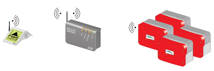
2 The Repeater
2.1 Applications
With the repeater, you can increase the Sunny Beam's range in order to reach the
inverters under problematic ambient conditions. The repeater can be simply integrated
into the existing transmission path from the Sunny Beam to the inverters. The repeater
requires a wall socket for the power supply.
2.2 Functions
Connection to the inverters and to the Sunny Beam via:
• Radio
(up to 325 ft in open air, up to 100 ft in buildings, maximum 4 inverters)
Supported inverters:
• The repeater supports all inverters that the Sunny Beam supports.
Number of inverters supported:
•up to 4
Connection to the power supply via:
• USB plug-in power supply (max. 6 ft)
Display of system states:
• via 4 light-emitting diodes
RepeaterSunny Beam U Inverters
The Repeater SMA Technologie AG
Page 10 SBRepU-11:NU0207 User Manual
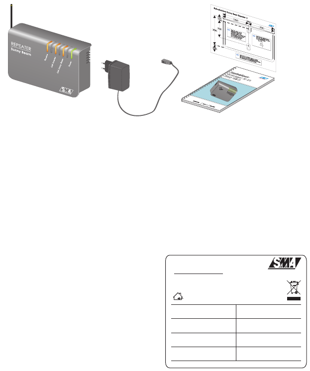
2.3 Scope of Delivery
2.4 Identification
2.4.1 Type Plate
You can identify the repeater using the type
plate (see figure to the right). The type plate is
located on the underside of the repeater.
A 1 repeater
B 1 USB plug-in power supply
C 1 user manual
D 1 drilling template
A
B
C
D
www.SMA.de
Nennspannung:
Nom. Voltage: 1012
Serien Nr.:
Serial No.:
Version:
Version:
REPEATER
Sunny Beam U
5 V DC
A1

SMA Technologie AG Safety Instructions
User Manual SBRepU-11:NU0207 Page 11
3 Safety Instructions
Please follow all operating and safety instructions in this manual. Failure to follow these
instructions could result in damage to the device and cause personal injury.
Only use the repeater in a dry environment. Otherwise, there is a risk of
electric shock.
The repeater must not be opened.
Only use the plug-in power supply delivered with the repeater.
Changes or modifications not expressly approved by the party
responsible for compliance could void the user’s authority to operate the
equipment.
Safety Instructions SMA Technologie AG
Page 12 SBRepU-11:NU0207 User Manual
SMA Technologie AG Determining the Installation Location
User Manual SBRepU-11:NU0207 Page 13
4 Determining the Installation Location
4.1 Requirements
Observe the following ambient conditions for the repeater's installation location.
• Protect the repeater from dust, wet conditions, corrosive substances and vapors.
• The repeater requires a 120 V wall socket for the power supply.
• The ambient temperature must be between 32 °F and 131 °F.
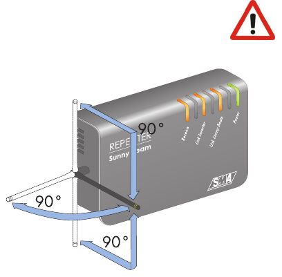
4.2 Handling the Antenna
With the Sunny Beam Repeater's adjustable antenna, you can adjust the alignment of
the antenna to suit the local conditions.
From the vertical position, the Sunny
Beam Repeater's antenna can be
rotated a maximum of 180 degrees to
the front or to the bottom. From the
horizontal position, the Sunny Beam's
antenna can also be tilted to the left in
two steps of 45 degrees, as illustrated
to the right.
The antenna may be rotated a maximum of 90 degrees to the front or to
the rear. Further rotation damages the cable.
Determining the Installation Location SMA Technologie AG
Page 14 SBRepU-11:NU0207 User Manual
4.3 Determination Procedure
1. Walk with the Sunny Beam into the range of the inverters and activate the Sunny
Beam as described in the Sunny Beam user manual. The inverters must be detected
and registered with the Sunny Beam.
2. Check that the inverters are operating.
3. Walk with the Sunny Beam until approximately three meters from the inverters (not
closer).
4. Set the data request frequency to the maximum frequency (the minimum selectable
interval) via the menu "VIEW OPTIONS/DATA REQUEST FREQ.".
5. Go to the "SETUP/SERVICE/DIAGNOSTICS" menu.
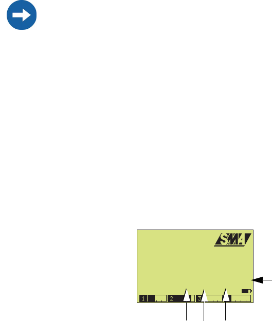
6. Here, you can read the communication quality (see figure below) which is
calculated on the basis of the ratio between the lost data packets and the sent data
packets.
The registered inverters are listed with the last five digits of the serial number. The
following values are also specified:
"S"= data packets sent
"LS"= data packets lost on sending
"LR" = data packets lost on receipt
This is followed by the communication quality calculated in %.
The communication quality specifies the ratio between received and sent data
packets of the registered inverters. With a communication quality of 100 %, the
signal strength is very good and no data packets are lost.
It is important to set the data request frequency back to at least 15 seconds once
you have successfully determined the installation locations of the repeater and the
Sunny Beam. Lower values (under 15 seconds) should only be set for
commissioning purposes (testing the radio connection) and not long-term.
3.PB V:0.00 4.PB V:0.00
SBeam V2.21US firmware
DIAGNOSTICS
1.PB V:2.10 2.PB V:2.04
DEVICE S LS LR
.67890: 204 0 0 100%
3.07V
.67891: 204 0 0 100% Communication quality
LRLSS
in %
SMA Technologie AG Determining the Installation Location
User Manual SBRepU-11:NU0207 Page 15
7. Move away with the Sunny Beam towards the desired installation location until the
first data packets are shown to be lost under LS or LR. Then move back towards
the inverters again until no more data packets are being lost.
8. Install the repeater at this location. First connect the provided USB power supply
to the repeater, then plug the power plug into a socket.
The repeater starts up.
All LEDs on the repeater briefly shine green. The repeater starts up. This procedure
takes approximately 1 minute.
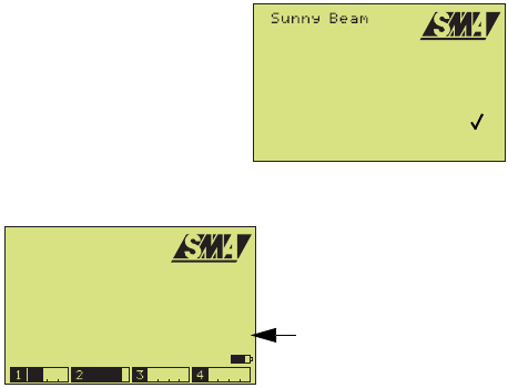
9. In the Sunny Beam main menu, select "SETUP/
PLANT" and set a check mark beside the menu
item "REPEATER".
10. Select "EXIT" repeatedly until the prompt window
opens.
11. Select "Yes" in the prompt window. The setting is
saved.
12. Return to the "SETUP/SERVICE/DIAGNOSTICS" menu.
13. You can now walk away with the Sunny Beam towards the desired installation
location until the communication quality is still at least 50 %.
14. If you have reached the desired installation location with sufficient communication
quality, commissioning is successfully completed at this point.
Set the data request frequency back to a value of at least 15 seconds or higher
via the menu "VIEW OPTIONS/DATA REQUEST FREQ.".
15. If you cannot yet reach the desired installation location with sufficient
communication quality, change the repeater's installation location. Even altering
the position by only a few meters may improve the communication quality.
16. After successful commissioning, set the data request frequency back to a value of
at least 15 seconds or higher via the menu "VIEW OPTIONS/DATA REQUEST
FREQ.".
PLANT
Sunny Boy DETECTION
EXCLUDE Sunny Boys
GROUP
REPEATER :
EXIT
3.PB V:0.00 4.PB V:0.00
SBeam V2.21US firmware
DIAGNOSTICS
1.PB V:2.10 2.PB V:2.04
DEVICE S LS LR
.67890: 204 0 0 100%
3.07V
.67891: 204 0 0 100% Communication quality
in %
Determining the Installation Location SMA Technologie AG
Page 16 SBRepU-11:NU0207 User Manual
4.4 Exemplary Installations
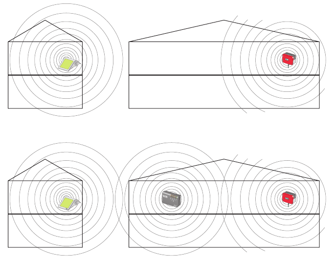
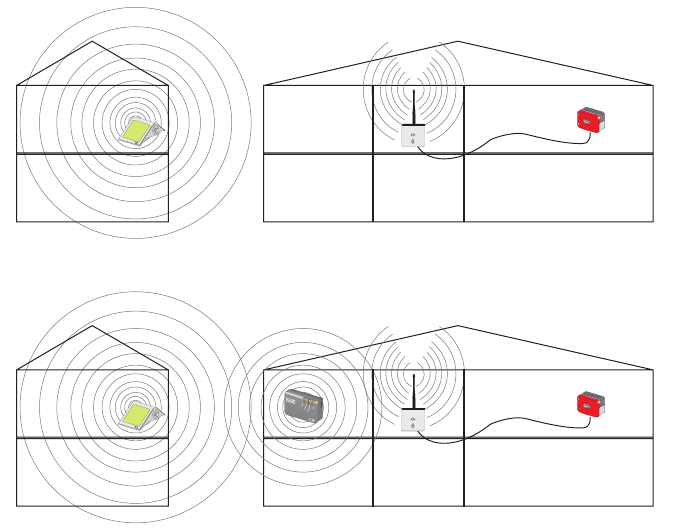
4.4.1 From Building to Building
If the radio connection from building to building is insufficient due to the buildings being
too far apart, or because of excessive attenuation, you can use the repeater to bridge
a transmission gap, or to improve a poor radio connection.
Sunny
Beam
Betrieb
Operation
Erdschluss
Earth Fault
Störung
Failure
Transmission gap (without repeater)
Bridging the transmission gap with the repeater
SMA Technologie AG Determining the Installation Location
User Manual SBRepU-11:NU0207 Page 17
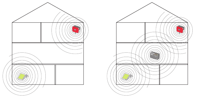
4.4.2 From Floor to Floor
If the radio connection within a building is insufficient due to the devices being too far
apart, or because of excessive attenuation through ceilings and walls, you can use the
repeater to bridge a transmission gap, or to improve a poor radio connection.
Sunny
Beam
Betrieb
Operation
Erdschluss
Earth Fault
Störung
Failure
Transmission gap
(without repeater)
Bridging the transmission gap
(with repeater)
Determining the Installation Location SMA Technologie AG
Page 18 SBRepU-11:NU0207 User Manual
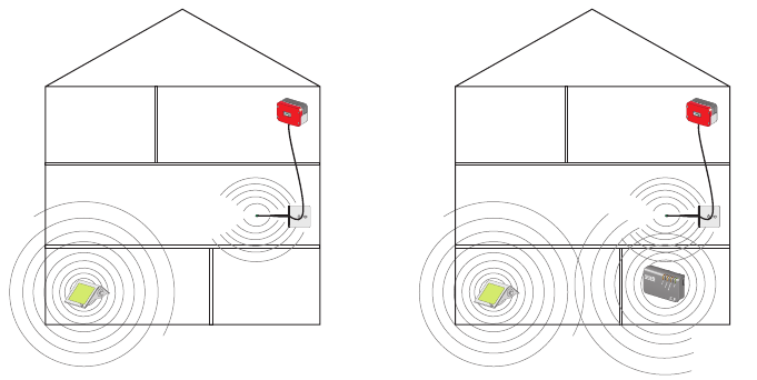
4.4.3 From Building to Building with External Antenna Kit
You can also use the repeater in conjunction with the external antenna kit from SMA.
With the external antenna kit, comprising an antenna bracket and extension cable, you
can bridge walls or ceilings.
Transmission gap (without repeater)
Bridging the transmission gap with the repeater
SMA Technologie AG Determining the Installation Location
User Manual SBRepU-11:NU0207 Page 19
4.4.4 From Floor to Floor with External Antenna Kit
You can also extend the external antenna kit with the repeater within a building. You
can bridge walls and ceilings with the external antenna kit. With the repeater, you can
then bridge any transmission gap that may still exist.
Transmission gap
(without repeater)
Bridging the transmission gap
(with repeater)
Determining the Installation Location SMA Technologie AG
Page 20 SBRepU-11:NU0207 User Manual

SMA Technologie AG Installation
User Manual SBRepU-11:NU0207 Page 21
5 Installation
The repeater can be used as a tabletop or wall-mounted device. If you choose to mount
the device on a wall, you can either mount it directly on the wall or on DIN rails.
5.1 Tabletop Device
If you use the repeater as a tabletop device, follow the points below:
• Do not cover the repeater. This can cause the device to overheat.
• Lay the USB power supply cable in such a manner that its weight does not cause
it to disconnect.
• Lay the cable properly so that there is no risk of persons tripping over it.
Only install the repeater once you have determined the appropriate installation
location as described in section 4 "Determining the Installation Location" (Page
13).
Installation SMA Technologie AG
Page 22 SBRepU-11:NU0207 User Manual
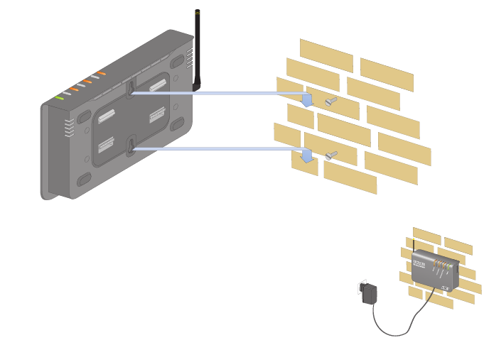
5.2 Wall Mounting
1. Pull the USB power supply plug out of the socket.
2. Pull the USB plug out of the repeater.
3. Use the drilling template to determine the position of the repeater on the wall.
Observe the USB power supply's cable length.
4. Mark the position of the drill holes.
5. Drill the holes and install the screws. Use screws with a shank diameter of
0.13 inch to 0.17 inch.
6. Leave about 0.25 inch clearance between the screw head and the wall.
7. Hang the repeater on the screws (see figure).
8. Plug the USB power supply's USB plug into the socket on
the lower edge of the repeater's housing.
9. Then plug the USB power supply's plug into the socket.
All LEDs on the repeater briefly shine green. The repeater
starts up. This procedure takes approximately 1 minute.
SMA Technologie AG Installation
User Manual SBRepU-11:NU0207 Page 23
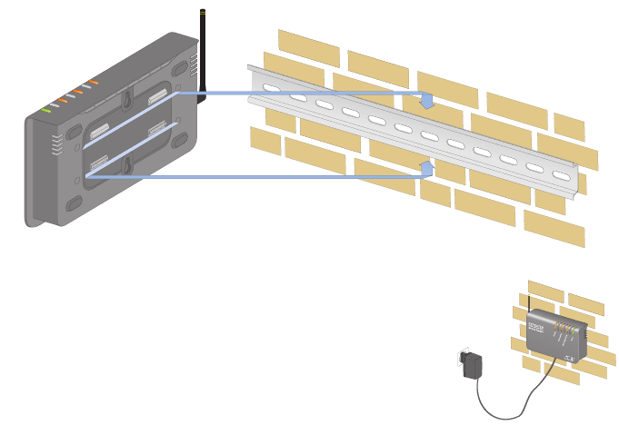
5.3 Top Hat Rail Installation
1. Pull the USB power supply plug out of the socket.
2. Pull the USB plug out of the repeater.
3. Fasten a top hat rail onto the wall. Observe the USB power supply's cable length.
4. Hook both lower retainers of the repeater under the lower edge of the top hat rail.
5. Push the repeater upwards.
6. Hook the repeater's two upper catches over the upper edge of the top hat rail.
7. Plug the USB power supply's USB plug into the socket on
the lower edge of the repeater's housing.
8. Then plug the USB power supply's plug into the socket.
All LEDs on the repeater briefly shine green. The repeater
starts up. This procedure takes approximately 1 minute.
Installation SMA Technologie AG
Page 24 SBRepU-11:NU0207 User Manual
SMA Technologie AG Explanation of the LEDs
User Manual SBRepU-11:NU0207 Page 25
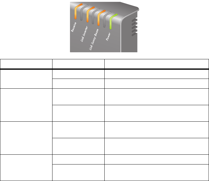
6 Explanation of the LEDs
The repeater has 4 LEDs, with which the status of the device can be ascertained. The
repeater is equipped with the following LEDs:
•Receive
• Link Inverter (connection to the inverter)
• Link Sunny Beam (connection to the Sunny Beam)
• Power (power supply)
This section explains the repeater's various light signals and flash signals.
LED Status/Color Display
Receive flashes orange Data are being received.
off No data are being received.
Link Inverter shines orange The repeater has received data from the
inverter.
off The repeater is not receiving any data
from the inverter.
Link Sunny Beam shines orange The repeater has received data from the
Sunny Beam.
off The repeater is not receiving any data
from the Sunny Beam.
Power shines green The power supply is ok.
off (All LEDs are off), no power supply is
present.
Explanation of the LEDs SMA Technologie AG
Page 26 SBRepU-11:NU0207 User Manual
SMA Technologie AG Maintenance and Cleaning
User Manual SBRepU-11:NU0207 Page 27
7 Maintenance and Cleaning
7.1 Maintenance
The repeater does not require maintenance.
7.2 Cleaning
Use a soft, damp cloth to clean your repeater. Make sure that the cloth is made of
scratch-free material so that the surface of the repeater will not be damaged.
If there is a considerable amount of dirt, you can also use a mild, non-corrosive cleaning
agent.
Maintenance and Cleaning SMA Technologie AG
Page 28 SBRepU-11:NU0207 User Manual
SMA Technologie AG Decommissioning
User Manual SBRepU-11:NU0207 Page 29
8 Decommissioning
8.1 Disassembly
Pull the USB plug-in power supply's plug out of the socket. Then pull the USB plug out
of the repeater.
8.2 Packaging for Shipment
When returning the device to us, be sure to use packaging which adequately protects
the device from damage during transport (if possible, the original packaging).
8.3 Disposal
Dispose of the repeater at an authorized disposal company.
Decommissioning SMA Technologie AG
Page 30 SBRepU-11:NU0207 User Manual

SMA Technologie AG Technical Data
User Manual SBRepU-11:NU0207 Page 31
9 Technical Data
Operation
Supported Devices The Sunny Beam Repeater U (FCCID: SVFSBEAMREPU)
operates only with the Sunny Beam U (FCCID:
SVFSUNNYBEAMU) and the SBEAMPB2-01 (FCCID:
SVFSPB2).
Dimensions
Size 8.85 x 5.12 x 2.24 inches (width x height x depth)
Vertically, the repeater requires an additional space of
approximately 6 inches for the cables.
Weight 1.65 lb
Power supply
USB plug-in power supply input voltage 100 V to 240 V, 47 Hz to 63 Hz
output voltage 5 V
Environmental conditions for operation
Ambient temperature 32 °F to 131 °F
Relative humidity 5 % to 95 %, non-condensing
Technical Data SMA Technologie AG
Page 32 SBRepU-11:NU0207 User Manual

SMA Technologie AG Contact
User Manual SBRepU-11:NU0207 Page 33
10 Contact
If you have any questions or queries, please contact us. A team of qualified engineers
and technicians is at your disposal.
Help us to help you by having the following information ready when you call us:
• Type of inverters and serial numbers
• Serial number of the repeater
• Serial number and firmware version of the Sunny Beam U
Address:
SMA America, Inc.
12438 Loma Rica Drive
Grass Valley, CA 95945
Phone: (530) 273-4895
Fax: (530) 274-7271
info@sma-america.com
www.sma-america.com
Legal Restrictions SMA Technologie AG
Page 34 SBRepU-11:NU0207 User Manual
The information contained in this document is the property of SMA Technologie AG. Publishing its content,
either partially or in full, requires the written permision of SMA Technologie AG. Any internal company
copying of the document for the purposes of evaluating the product or its correct implementation is allowed
and does not require permission.
Exclusion of liability
The general terms and conditions of delivery of SMA Technologie AG shall apply.
The content of these documents is continually checked and amended, where necessary. However,
discrepancies cannot be excluded. No guarantee is made for the completeness of these documents. The
latest version is available on the Internet at www.SMA.de or from the usual sales channels.
Guarantee or liability claims for damages of any kind are exlcuded if they are caused by one or more of the
following:
• Improper or inappropriate use of the product
• Operating the product in an unintended environment
• Operating the product whilst ignoring relevant, statutory safety regulations in the deployment location
• Ignoring safety warnings and instructions contained in all documents relevant to the product
• Operating the product under incorrect safety or protection conditions
• Altering the product or supplied software without authority
• The product malfunctions due to operating attached or neighboring devices beyond statutory limit values
• In case of unforeseen calamity or force majeure
Software licensing
The use of supplied software produced by SMA Technologie AG is subject to the following conditions:
This software may be copied for internal company purposes and may be installed on any number of
computers. Supplied source codes may be changed or adapted for internal company purposes on your own
responsibility. Drivers may also be transferred to other operating systems. Source codes may only be
published with the written permission of SMA Technologie AG. Sub-licensing of software is not permissible.
Limitation of liability: SMA Technologie AG rejects any liability for direct or indirect damages arising from
the use of software developed by SMA Technologie AG. This also applies to the provision or non-provision
of support activities.
Supplied software not developed by SMA Technologie AG is subject to the respective licensing and liability
agreements of the manufacturer.
Trademarks
All trademarks are recognized even if these are not marked separately. Missing designations do not mean
that a product or brand is not a registered trademark.
SMA Technologie AG
Hannoversche Straße 1-5
34266 Niestetal
Germany
Tel. +49 561 9522-0
Fax +49 561 9522-100
www.SMA.de
E-mail: info@SMA.de
© 2005 SMA Technologie AG. All rights reserved.

www.sma-america.com
SMA America, Inc.
12438 Loma Rica Drive, Unit C
Grass Valley, CA 95945
Phone 530.273.4895
Fax 530.274.7271
info@sma-america.com
Toll Free 888-4SMAUSA
SMA Ibérica Tecnología Solar, S.L.
Barcelona, Spain
E-mail: info@SMA-Iberica.com
SMA Italia S.r.l.
Milan, Italy
E-mail: info@SMA-Italia.com
SMA Technologie AG
Niestetal, Germany
E-mail: info@SMA.de
SMA Solar Technology China
Beijing, P.R. China
E-mail: info@SMA-China.com
SMA Technology Korea Co., Ltd.
Seoul, Korea
E-mail: info@SMA-Korea.com