SMC Networks 8014WN2 Cable Wireless Router User Manual
SMC Networks Inc Cable Wireless Router
user manual

DOCSIS 2.0 Wireless Cable Modem Gatewa
y
FastFind Links
Getting to Know the Gateway
Installing the Gateway
Configuring Your Computer for TCP/IP
Configuring the Gateway
SMC8014WN and
SMC8014WN2
Administrator Manual
SMC Networks
20 Mason
Irvine, CA. 92618
U.S.A.
Copyright © 2012 SMC Networks
All Rights Reserved
Information furnished by SMC Networks, Inc. (SMC) is believed to be accurate and reliable. However,
no responsibility is assumed by SMC for its use, or for any infringements of patents or other rights of
third parties which may result from its use. No license is granted by implication or otherwise under
any patent or patent rights of SMC. SMC reserves the right to change specifications at any time
without notice
No part of this publication may be reproduced or transmitted in any form or by any means, electronic
or mechanical, including photocopying and recording, or stored in a database or retrieval system for
any purpose without the express written permission of SMC.
Microsoft and Windows are registered trademarks of Microsoft Corporation. Apple and Macintosh are
registered trademarks of Apple, Inc. All other brands, product names, trademarks, or service marks
are property of their respective owners.
This product (Model :SMC8014WN and SMC8014WN2) includes software code developed by third
parties, including software code subject to the GNU General Public License (“GPL”) or GNU Lesser
General Public License (LGPL”). As applicable, the terms of the GPL and LGPL, and information on
obtaining access to the GPL code and LGPL used in this product, are available to you at
http://gpl.smc.com/. The GPL code and LGPL code used in this product is distributed WITHOUT ANY
WARRANTY and is subject to the copyrights of one or more authors. For details, see the GPL Code
and LGPL Code for this product and the terms of the GPL and LGPL.
SMC8014WN and SMC8014WN2 Wireless Cable Modem Gateway Administrator Manual

iii
SMC8014WN and SMC8014WN2 Wireless Cable Modem Gateway Administrator Manual
Contents
Preface...................................................................................................................... v
Key Features.................................................................................................................vi
Document Organization ...............................................................................................vii
Document Conventions................................................................................................vii
Models Covered in this Guide................................................................................vii
Safety and Warnings..............................................................................................vii
Typographic Conventions ........................................................................................... viii
1 Getting to Know the Gateways............................................................................ 9
Unpacking Package Contents .................................................................................... 10
System Requirements................................................................................................. 10
Hardware Overview .................................................................................................... 11
SMC8014WN Front and Rear panels................................................................... 11
SMC8014WN2 Front and Rear panels................................................................. 13
Restoring Factory Defaults ......................................................................................... 15
Rebooting the Gateway .............................................................................................. 15
2 Installing the Gateway........................................................................................ 16
Finding a Suitable Location ........................................................................................ 17
Connecting to the LAN................................................................................................ 17
Connecting the WAN .................................................................................................. 18
Powering on the Gateway........................................................................................... 18
3 Configuring Your Computer for TCP/IP ............................................................ 19
Configuring Microsoft Windows 2000......................................................................... 20
Configuring Microsoft Windows XP ............................................................................ 21
Configuring Microsoft Windows Vista......................................................................... 22
Configuring Microsoft Windows 7............................................................................... 24
Configuring an Apple® Macintosh® Computer ............................................................ 27
4 Configuring the Gateway ................................................................................... 28
Pre-configuration Guidelines ...................................................................................... 29
Disabling Proxy Settings....................................................................................... 29
Disabling Proxy Settings in Internet Explorer................................................. 29
Disabling Proxy Settings in Firefox................................................................. 30
Disabling Proxy Settings in Safari .................................................................. 30
Disabling Firewall and Security Software............................................................. 30

Contents
iv
SMC8014WN and SMC8014WN2 Wireless Cable Modem Gateway Administrator Manual
Accessing the Gateway’s Web Management............................................................. 31
Understanding the Web Management Interface Screens.......................................... 32
Web Management Interface Menus and Submenus.................................................. 33
System Settings Menu.......................................................................................... 35
Password Settings Menu ................................................................................ 37
Remote Management Menu ........................................................................... 39
Customer UI Setup Menu ............................................................................... 41
WAN Settings Menu.............................................................................................. 43
MAC Spoofing Menu....................................................................................... 45
LAN Settings Menu ............................................................................................... 46
Ether Switch Port Control Menu ..................................................................... 48
Wireless Basic Settings Menu .............................................................................. 50
Port Forwarding Menu .......................................................................................... 52
Security Settings (Firewall) Menu......................................................................... 57
Access Control Menu...................................................................................... 58
Special Application Menu ............................................................................... 62
URL Blocking Menu ........................................................................................ 65
Schedule Rule Menu....................................................................................... 68
Email/Syslog Alert Menu................................................................................. 69
DMZ (Demilitarized Zone) Menu .................................................................... 72
Configuration Tools Menu..................................................................................... 73
Backing Up the Gateway’s Current Configuration Locally ............................. 74
Restoring the Gateway’s Current Configuration Locally ................................ 75
Backing Up the Gateway’s Current Configuration Remotely ......................... 76
Restoring the Gateway’s Current Configuration Remotely ............................ 76
Restoring Factory Defaults ............................................................................. 77
Reboot Menu......................................................................................................... 79
Diagnostics Menu ................................................................................................. 80
Using the Ping Tool......................................................................................... 81
Using the Trace Route Tool............................................................................ 82
Sending Inspected Traffic to a Log Server..................................................... 83
Status Menu .......................................................................................................... 84
Cable Status Menu ............................................................................................... 86
Appendix A - Wall Mounting the SMC8014WN.................................................... 87
Appendix B - Compliances ................................................................................... 89
Index ....................................................................................................................... 90
v
SMC8014WN and SMC8014WN2 Wireless Cable Modem Gateway Administrator Manual
Preface
Congratulations on your purchase of the SMC8014WN or SMC8014WN2 Wireless Cable
Modem Gateway. The SMC8014WN and SMC8014WN2 Wireless Cable Modem Gateways
are ideal all-in-one wired and wireless solutions for the home or business environment. SMC
is proud to provide you with a powerful, yet simple, communication device for connecting
your local area network (LAN) to the Internet.
This user manual contains all the information administrators need to install and configure
your new Wireless Cable Modem Gateway.
SMC8014WN SMC8014WN2

Preface
vi
SMC8014WN and SMC8014WN2 Wireless Cable Modem Gateway Administrator Manual
Key Features
The following list summarizes the Gateway’s key features.
y Integrated CableLabs-compliant DOCSIS 1.1 and 2.0 cable modem
y Internet connection to cable modem service via an integrated cable modem port
y High-speed 300 Mbps IEEE 802.11b/g/n wireless Access Point - interoperable with
multiple vendors
y Wireless WEP, WPA, and WPA2 encryption, hide SSID, and MAC filtering
y Local network connection via four 10/100 Mbps auto-sensing LAN ports with auto-
MDI/MDIX feature
y DHCP for dynamic IP configuration, and DNS for domain name mapping
y Firewall with Stateful Packet Inspection, client privileges, hacker prevention, DoS, and
NAT
y Universal Plug and Play (UPnP) allows to enable any UPnP device seamlessly
y Quality of Service (QoS) to ensure high-quality performance with existing networks
y Comprehensive LEDs for network status and troubleshooting
y Reset button
y Easy setup through a Web browser regardless of operating system.
y Compatible with all popular Internet applications
Note: Cable modems can provide data rates up to 38 Mbps downstream and 10
Mbps upstream. However, the actual rate provided by specific service providers
can vary dramatically from these upper limits.
Preface
vii
SMC8014WN and SMC8014WN2 Wireless Cable Modem Gateway Administrator Manual
Document Organization
This document consists of four chapters and two appendixes.
y Chapter 1 - describes the contents in the Gateway package, system requirements, and
an overview of the Gateway’s front and rear panels.
y Chapter 2 - describes how to install the Gateway.
y Chapter 3 - describes how to configure TCP/IP settings on the computer you will use to
configure the Gateway.
y Chapter 4 - describes how to configure the Gateway.
y Appendix A - provides wall-mounting instructions for the SMC8014WN Gateway.
y Appendix B - contains compliance information.
Document Conventions
This document uses the following conventions to draw your attention to certain information.
Models Covered in this Guide
This document covers the SMC8014WN and SMC8014WN2 Gateways. The term “Gateway”
is used to collectively refer to both models. If information in this document applies to one
model only, that model is identified.
Safety and Warnings
This document uses the following symbols to draw your attention to certain information.
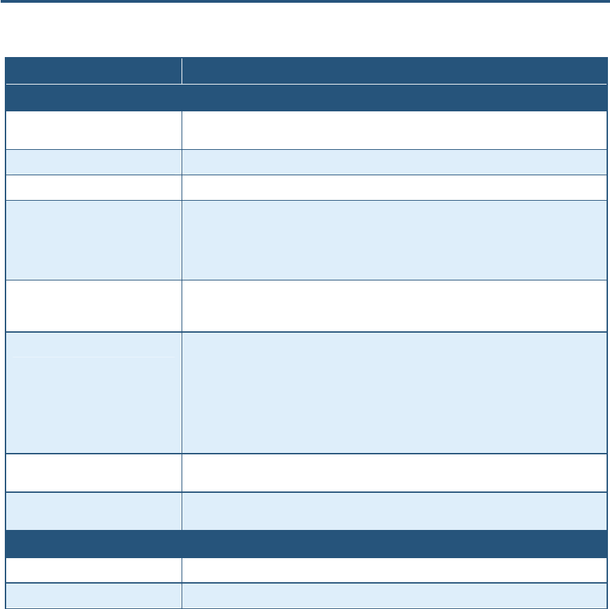
Symbol Meaning Description
Note Notes emphasize or supplement important points of the main text.
Tip Tips provide helpful information, guidelines, or suggestions for performing tasks more
effectively.
Warning Warnings indicate that failure to take a specified action could result in damage to the
device.
Electric Shock Hazard This symbol warns users of electric shock hazard. Failure to take appropriate
precautions such as not opening or touching hazardous areas of the equipment could
result in injury or death.
Preface
viii
SMC8014WN and SMC8014WN2 Wireless Cable Modem Gateway Administrator Manual
Typographic Conventions
This document also uses the following typographic conventions.
Convention Description
Bold Indicates text on a window, other than the window title, including menus, menu options, buttons, fields, and labels.
Italic Indicates a variable, which is a placeholder for actual text provided by the user or system. Angled brackets (< >)
are also used to indicate variables.
screen/code Indicates text that is displayed on screen or entered by the user.
< > angled
brackets Indicates a variable, which is a placeholder for actual text provided by the user or system. Italic font is also used to
indicate variables.
[ ] square
brackets Indicates optional values.
{ } braces Indicates required or expected values.
| vertical bar Indicates that you have a choice between two or more options or arguments.

9
SMC8014WN and SMC8014WN2 Wireless Cable Modem Gateway Administrator Manual
1 Getting to Know the Gateways
Before you install the Gateway, check the package contents and become familiar with the
Gateway’s front and rear panels.
The topics covered in this chapter are:
y Unpacking Package Contents (page 10)
y System Requirements (page 10)
y Hardware Overview (page 11)
y Restoring Factory Defaults (page 15)
y Rebooting the Gateway (page 15)

錯誤! 尚未定義樣式。
10
SMC8014WN and SMC8014WN2 Wireless Cable Modem Gateway Administrator Manual
Unpacking Package Contents
The SMC8014WN and SMC8014WN2 packages should include the following items:
y One SMC8014WN or SMC8014WN2 Wireless Cable Modem Gateway
y One external power supply 12V 1.25mA
y One Category 5E Ethernet cable
System Requirements
To complete the installation, you will need the following items:
y Provisioned Internet access on a cable network that supports cable modem service
y A computer with a wired network adapter with TCP/IP installed
y A Java-enabled Web browser, such as Microsoft Internet Explorer 5.5 or above
y Microsoft® Windows® 98 second edition or higher for USB driver support
錯誤! 尚未定義樣式。
11
SMC8014WN and SMC8014WN2 Wireless Cable Modem Gateway Administrator Manual
Hardware Overview
SMC8014WN Front and Rear panels
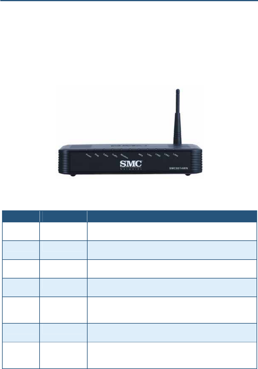
The front panel of the SMC8014WN Wireless Cable Modem Gateway contains a set of light-
emitting diode (LED) indicators that show the status of the Gateway and simplify
troubleshooting. Figure 1 shows the front panel LEDs and Table 1 describes the them.
Figure 1. Front Panel of the SMC8014WN Wireless Cable Modem Gateway
Table 1. SMC8014WN Front Panel LEDs
LED Color Description
Power Green ON = power is supplied to the Gateway.
OFF = power is not supplied to the Gateway.
Diag Green ON =- system failure. Reboot Gateway.
OFF = normal operation.
Cable Green ON = connected to cable network successfully.
Flashing = attempting to connect to network.
Traffic Green ON = cable modem has finished CMTS registration.
Flashing = attempting to register with CMTS.
Wireless Green ON = wireless enabled.
Flashing = data is transmitting.
OFF = wireless disabled.
WPS Green ON = enabled.
Flashing = data is transmitting.
LAN (1-4) Green ON = connected at 10 Mbps or 100 Mbps.
Flashing = data is transmitting.
OFF = no Ethernet link is detected.
錯誤! 尚未定義樣式。
12
SMC8014WN and SMC8014WN2 Wireless Cable Modem Gateway Administrator Manual
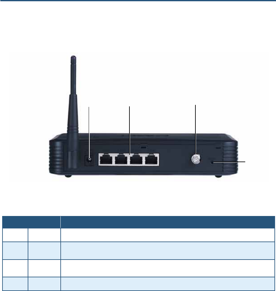
The rear panel of the SMC8014WN Wireless Cable Modem Gateway contains a reset button
and the ports for attaching the supplied power adapter and making additional connections.
Figure 2 shows the rear panel components and Table 2 describes them.
Figure 2. Rear Panel of SMC8014WN Wireless Cable Modem Gateway
Table 2. SMC8014WN Rear Panel
Item Description
n Power Connect the included power adapter to this port.
o Reset Use this button to reset the power or restore the default factory settings. The button is recesses to
prevent accidental resets. Use a paper clip or a pencil tip to push the Reset button.
p LAN 1-4 Four 10/100 auto-sensing switch (RJ-45) ports. Connect your local-area network devices, such as a PC,
hub, or switch, to these ports.
q CATV Connect your cable line to this port.
n op
q
錯誤! 尚未定義樣式。
13
SMC8014WN and SMC8014WN2 Wireless Cable Modem Gateway Administrator Manual
SMC8014WN2 Front and Rear panels
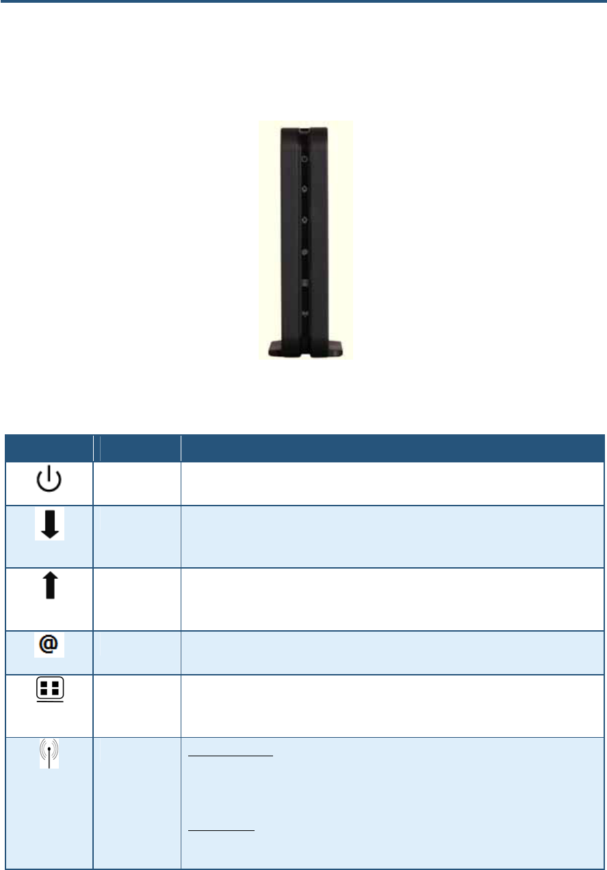
The front panel of the SMC8014WN2 Wireless Cable Modem Gateway contains a set of
light-emitting diode (LED) indicators that show the status of the Gateway and simplify
troubleshooting. Figure 3 shows the front panel LEDs and Table 3 describes the them.
Figure 3. Front Panel of the SMC8014WN2 Wireless Cable Modem Gateway
Table 3. SMC8014WN2 Front Panel LEDs
Icon Icon Name Description
Power Green = power is supplied to the Gateway.
OFF = power is not supplied to the Gateway.
DS Green Flashing =-attempt to connect to downstream frequency.
Green On = Gateway is connected to downstream frequency.
OFF = not scanning.
US Green Flashing= attempt to connect upstream frequency
Green ON = Gateway is connected to upstream frequency.
OFF = not scanning.
Status Green ON = cable modem has finished CMTS registration.
Green Flashing = cable modem is attempting to register with CMTS.
LAN Green ON = connected at 10 Mbps or 100 Mbps
Green Flashing = data is transmitting.
OFF = no Ethernet link is detected.
WLAN/WPS Wireless Function
Green ON = wireless interface is enabled.
Green Flashing= data is transmitting.
OFF = wireless interface is disabled.
WPS Function
Green and Red dual colors LED generate WPS LED behavior . Disable WLAN control ability
to avoid WPS LED behavior if LED works as WPS function.
錯誤! 尚未定義樣式。
14
SMC8014WN and SMC8014WN2 Wireless Cable Modem Gateway Administrator Manual
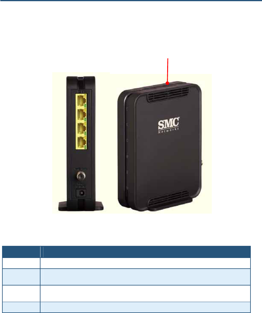
The rear panel of the SMC8014WN2 Wireless Cable Modem Gateway contains a reset
button and the ports for attaching the supplied power adapter and making additional
connections. Figure 4 shows the rear panel components and Table 4 describes them.
Figure 4. Rear Panel of SMC8014WN2 Wireless Cable Modem Gateway
Table 4. SMC8014WN2 Rear Panel
Item Description
Power Connect the included power adapter to this port.
Reset Use this button to reset the power or restore the default factory settings. The button is recesses to prevent
accidental resets. Use a paper clip or a pencil tip to push the Reset button.
ETH 1-4 Four 10/100 auto-sensing switch (RJ-45) ports. Connect your local-area network devices, such as a PC,
hub, or switch, to these ports.
CATV Connect your cable line to this port.
Reset button

錯誤! 尚未定義樣式。
15
SMC8014WN and SMC8014WN2 Wireless Cable Modem Gateway Administrator Manual
Restoring Factory Defaults
The Reset button on the rear panel can be used to return the Gateway to its factory default
settings. As a result, any changes made to the Gateway’s default settings will be lost.
If you do not have physical access to the Gateway, you can use the GUI to either power
cycle the Gateway (see “Reboot Menu” on page 79) or return the Gateway to its factory
default settings (see “Restoring Factory Defaults” on page 77).
The following procedure describes how to use the Reset button to power cycle the Gateway
and return it to its original factory default settings.
1. Leave power plugged into the Gateway.
2. Find the Reset button on the rear panel, then press and hold it for at least 10 seconds.
3. Release the Reset button.
Rebooting the Gateway
If the Gateway has problems connecting to the Internet, hold down the Reset button on the
rear panel for 1 second and then release.

16
SMC8014WN and SMC8014WN2 Wireless Cable Modem Gateway Administrator Manual
2 Installing the Gateway
This chapter describes how to install the SMC8014WN and SMC8014WN2 Wireless Cable
Modem Gateways. The topics covered in this chapter are:
y Finding a Suitable Location (page 17)
y Connecting to the LAN (page 17)
y Connecting the WAN (page 18)
y Powering on the Gateway (page 18)

錯誤! 尚未定義樣式。
17
SMC8014WN and SMC8014WN2 Wireless Cable Modem Gateway Administrator Manual
Finding a Suitable Location
The Gateways can be installed in any location with access to the cable network. All of the
cables connect to the rear panel of the Gateway for better organization and utility. The LED
indicators on the front panel are easily visible to provide users with information about
network activity and status.
For optimum performance, the location you choose should:
y Be close to a working AC power outlet
y Allow sufficient airflow around the Gateway to keep the device as cool as possible
y Not expose the Gateway to a dusty or wet environment
y Be an elevated location such as a high shelf, keeping the number of walls and ceilings
between the Gateway and your other devices to a minimum
y Be away from electrical devices that are potential sources of interference, such as ceiling
fans, home security systems, microwaves, or the base for a cordless phone
y Be away from any large metal surfaces, such as a solid metal door or aluminum studs.
Large expanses of other materials such as glass, insulated walls, fish tanks, mirrors,
brick, and concrete can also affect your wireless signal
Connecting to the LAN
Using an Ethernet LAN cable, you can connect the Gateway to a PC or notebook computer,
hub, or switch. The Gateways support auto-MDI/MDIX, so you can use either a standard
straight-through or crossover Ethernet cable.
1. Connect either end of an Ethernet cable to one of the four LAN ports on the rear panel of
the Gateway (see Figure 5).
Figure 5. Connecting to a LAN Port on the Gateway Rear Panel
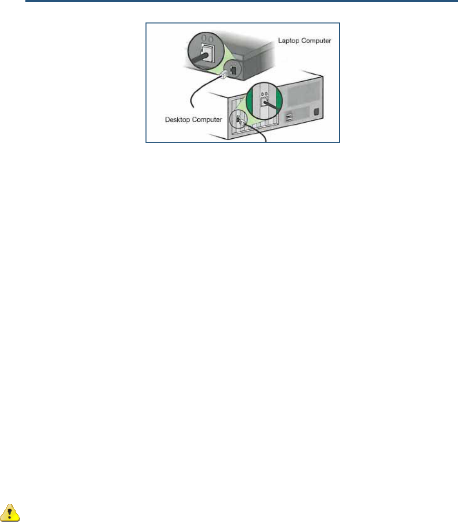
2. Connect the other end of the cable to your computer’s network-interface card (NIC) or to
another network device (see Figure 6).
錯誤! 尚未定義樣式。
18
SMC8014WN and SMC8014WN2 Wireless Cable Modem Gateway Administrator Manual
Figure 6. Connecting the Gateway to the a Laptop or Desktop Computer
Connecting the WAN
To connect the Gateway to a Wide Area Network (WAN) interface:
1. Connect a coaxial cable to the port labeled CATV on the rear panel of the Gateway from a
cable port in your home or office (see Figure 2 on page 6 or Figure 4 on page 14). Use
only manufactured coaxial patch cables with F-type connectors at both ends for all
connections.
2. Hand-tighten the connectors to secure the connection.
Powering on the Gateway
After making your LAN and WAN connections, use the following procedure to power on the
Gateway:
1. Connect the supplied power cord to the port on the rear panel of the Gateway (see Figure
2 on page 6 or Figure 4 on page 14).
2. Connect the other end of the power cord to a working power outlet. The Gateway powers
on automatically, the Power LED on the front panel goes ON, and the other front panel
LEDs show the Gateway’s status (see Table 1 on page 11 or Table 3 on page 13).
WARNING: Only use the power cord supplied with the Gateway. Using a different
power cord can damage the Gateway and void the warranty.

19
SMC8014WN and SMC8014WN2 Wireless Cable Modem Gateway Administrator Manual
3 Configuring Your Computer for TCP/IP
After you install the SMC8014WN or SMC8014WN2 Wireless Cable Modem Gateway,
configure the TCP/IP settings on a computer that will be used to configure the Gateway. This
chapter describes how to configure TCP/IP for various Microsoft Windows and Apple
Macintosh operating systems.
The topics covered in this chapter are:
y Configuring Microsoft Windows 2000 (page 20)
y Configuring Microsoft Windows XP (page 21)
y Configuring Microsoft Windows Vista (page 22)
y Configuring Microsoft Windows 7 (page 24)
y Configuring an Apple® Macintosh® Computer (page 27)
錯誤! 尚未定義樣式。
20
SMC8014WN and SMC8014WN2 Wireless Cable Modem Gateway Administrator Manual
Configuring Microsoft Windows 2000
Use the following procedure to configure your computer if your computer has Microsoft
Windows 2000 installed.
1. On the Windows taskbar, click Start, point to Settings, and then click Control Panel.
2. In the Control Panel window, double-click the Network and Dial-up Connections icon. If
the Ethernet adapter in your computer is installed correctly, the Local Area Connection
icon appears.
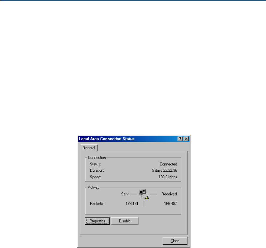
3. Double-click the Local Area Connection icon for the Ethernet adapter connected to the
Gateway. The Local Area Connection Status dialog box appears (see Figure 7).
Figure 7. Local Area Connection Status Window
4. In the Local Area Connection Status dialog box, click the Properties button. The Local
Area Connection Properties dialog box appears.
5. In the Local Area Connection Properties dialog box, verify that Internet Protocol (TCP/IP)
is checked. Then select Internet Protocol (TCP/IP) and click the Properties button.
6. Click Obtain an IP address automatically to configure your computer for DHCP.
7. Click the OK button to save this change and close the Local Area Connection Properties
dialog box.
8. Click OK button again to save these new changes.
9. Restart your computer.
錯誤! 尚未定義樣式。
21
SMC8014WN and SMC8014WN2 Wireless Cable Modem Gateway Administrator Manual
Configuring Microsoft Windows XP
Use the following procedure to configure a computer running Microsoft Windows XP with the
default interface. If you use the Classic interface, where the icons and menus resemble
previous Windows versions, perform the procedure under “Configuring Microsoft Windows
2000” on page 20.
1. On the Windows taskbar, click Start, click Control Panel, and then click Network and
Internet Connections.
2. Click the Network Connections icon.
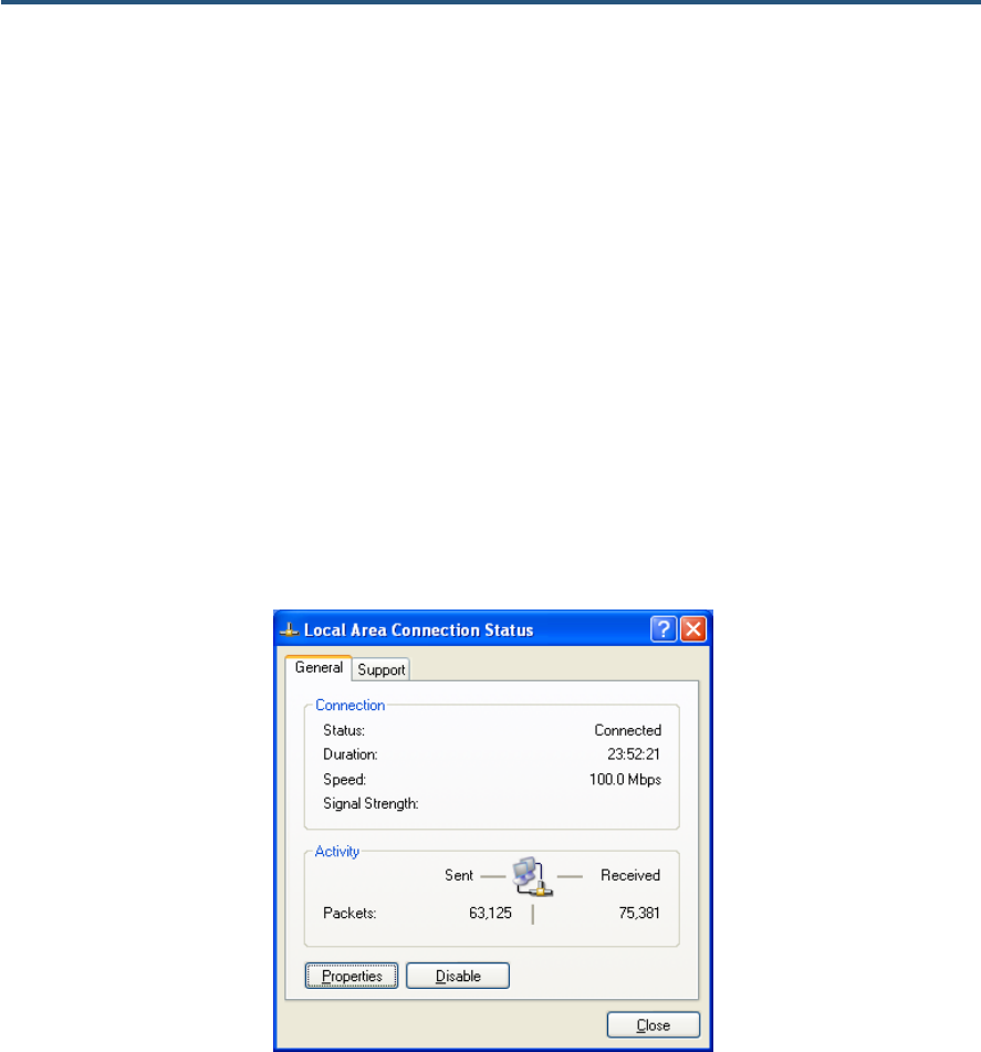
3. Click Local Area Connection for the Ethernet adapter connected to the Gateway. The
Local Area Connection Status dialog box appears.
4. In the Local Area Connection Status dialog box, click the Properties button (see Figure 8).
The Local Area Connection Properties dialog box appears.
Figure 8. Local Area Connection Status Window
5. In the Local Area Connection Properties dialog box, verify that Internet Protocol (TCP/IP)
is checked. Then select Internet Protocol (TCP/IP) and click the Properties button. The
Internet Protocol (TCP/IP) Properties dialog box appears.
6. In the Internet Protocol (TCP/IP) Properties dialog box, click Obtain an IP address
automatically to configure your computer for DHCP. Click the OK button to save this
change and close the Internet Protocol (TCP/IP) Properties dialog box.
7. Click the OK button again to save your changes.
8. Restart your computer.
錯誤! 尚未定義樣式。
22
SMC8014WN and SMC8014WN2 Wireless Cable Modem Gateway Administrator Manual
Configuring Microsoft Windows Vista
Use the following procedure to configure a computer running Microsoft Windows Vista with
the default interface. If you use the Classic interface, where the icons and menus resemble
previous Windows versions, perform the procedure under “Configuring Microsoft Windows
2000” on page 20.
1. On the Windows taskbar, click Start, click Control Panel, and then select the Network
and Internet icon.
2. Click View Networks Status and tasks and then click Management Networks
Connections.
3. Right-click the Local Area Connection icon and click Properties.
4. Click Continue. The Local Area Connection Properties dialog box appears.
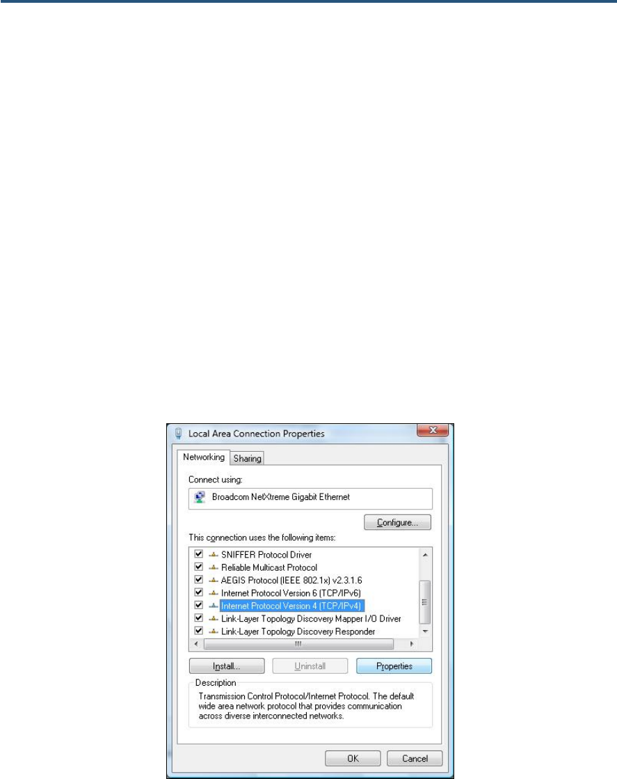
5. In the Local Area Connection Properties dialog box, verify that Internet Protocol
(TCP/IPv4) is checked. Then select Internet Protocol (TCP/IPv4) and click the
Properties button (see Figure 9). The Internet Protocol Version 4 Properties dialog box
appears.
Figure 9. Local Area Connection Properties Window
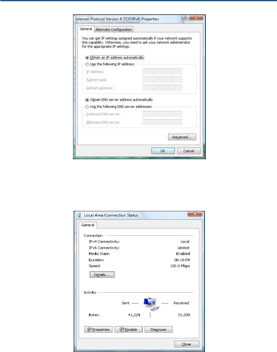
6. In the Internet Protocol Version 4 Properties dialog box, click Obtain an IP address
automatically to configure your computer for DHCP (see Figure 10).
錯誤! 尚未定義樣式。
23
SMC8014WN and SMC8014WN2 Wireless Cable Modem Gateway Administrator Manual
Figure 10. Internet Protocol Properties Window
7. Click the OK button to save your changes and close the dialog box.
8. Click the OK button again to save your changes.
Figure 11. Local Area Connection Status Window
錯誤! 尚未定義樣式。
24
SMC8014WN and SMC8014WN2 Wireless Cable Modem Gateway Administrator Manual
Configuring Microsoft Windows 7
Use the following procedure to configure a computer running Microsoft Windows 7.
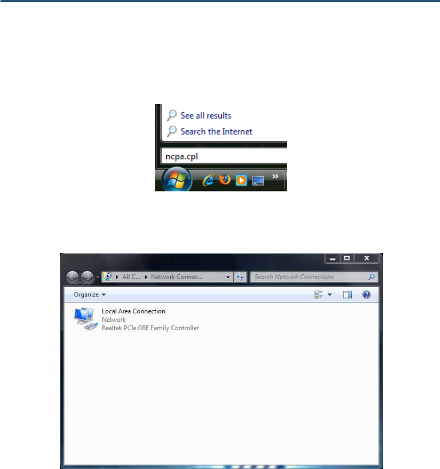
1. In the Start menu search box, type: ncpa.cpl
Figure 12. Typing ncpa.cpl in the Start Menu Box
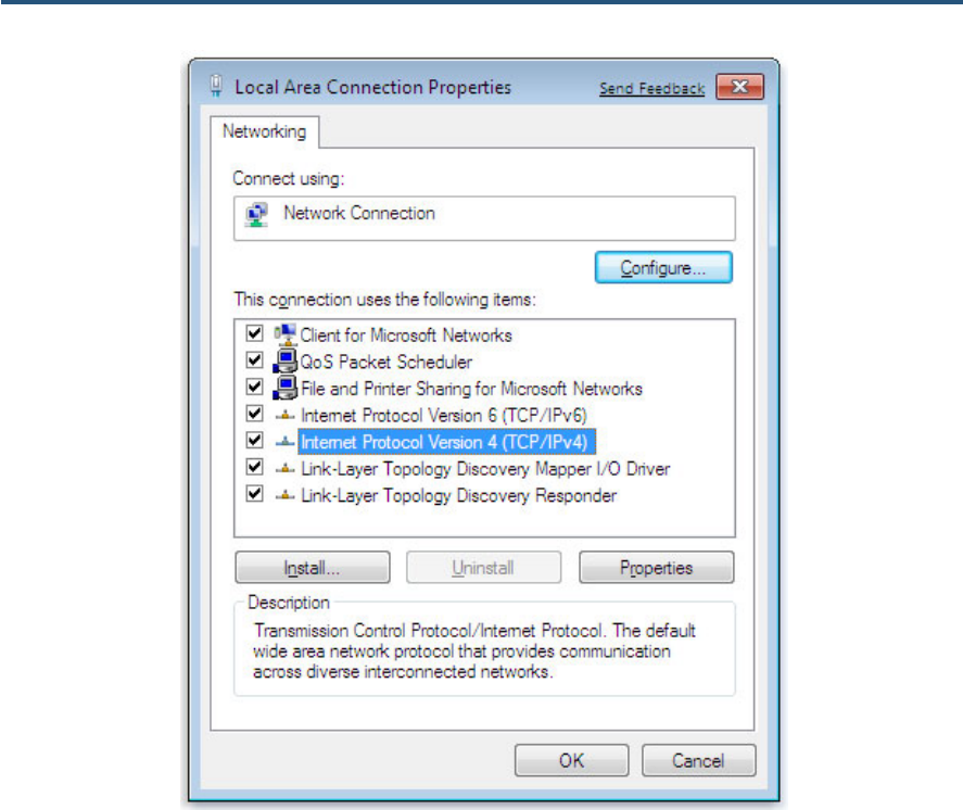
The Network Connections List appears.
Figure 13. Example of Network Connections List
2. Right-click the Local Area Connection icon and click Properties.
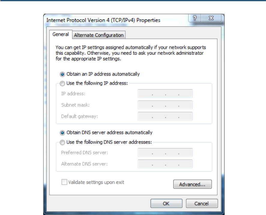
3. In the Networking tab, click either Internet Protocol Version 4 (TCP/IPv4) or Internet
Protocol Version 6 (TCP/IPv6), and then click Properties.
錯誤! 尚未定義樣式。
25
SMC8014WN and SMC8014WN2 Wireless Cable Modem Gateway Administrator Manual
Figure 14. Local Area Network Connection Properties Dialog Box
4. In the properties dialog box, click Obtain an IP address automatically to configure your
computer for DHCP (see Figure 15).
錯誤! 尚未定義樣式。
26
SMC8014WN and SMC8014WN2 Wireless Cable Modem Gateway Administrator Manual
Figure 15. Properties Window
5. Click the OK button to save your changes and close the dialog box.
6. Click the OK button again to save your changes.
錯誤! 尚未定義樣式。
27
SMC8014WN and SMC8014WN2 Wireless Cable Modem Gateway Administrator Manual
Configuring an Apple® Macintosh® Computer
The following procedure describes how to configure TCP/IP on an Apple Macintosh running
Mac OS 10.2. If your Apple Macintosh is running Mac OS 7.x or later, the steps you perform
and the screens you see may differ slightly from the following. However, you should still be
able to use this procedure as a guide to configuring your Apple Macintosh for TCP/IP.
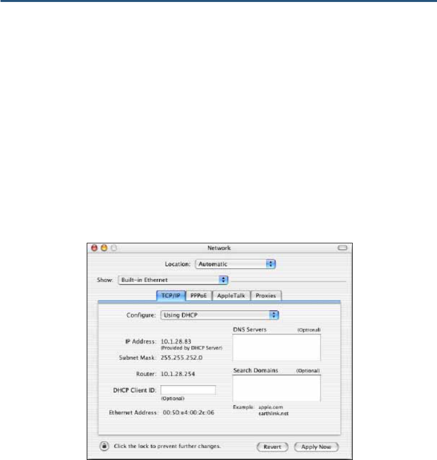
1. Pull down the Apple Menu, click System Preferences, and select Network.
2. Verify that the NIC connected to the SMC8014WN or SMC8014WN2 is selected in the
Show field.
3. In the Configure field on the TCP/IP tab, select Using DHCP (see Figure 16).
4. Click Apply Now to apply your settings and close the TCP/IP dialog box.
Figure 16. Selecting Using DHCP in the Configure Field

28
SMC8014WN and SMC8014WN2 Wireless Cable Modem Gateway Administrator Manual
4 Configuring the Gateway
This chapter describes how to use a Web browser to configure the Gateway.
The topics covered in this chapter are:
y Pre-configuration Guidelines (page 29)
y Accessing the Gateway’s Web Management (page 31)
y Understanding the Web Management Interface Screens (page 32)
y Web Management Interface Menus (page 33)

錯誤! 尚未定義樣式。
29
SMC8014WN and SMC8014WN2 Wireless Cable Modem Gateway Administrator Manual
Pre-configuration Guidelines
Before you configure the Gateway, observe the guidelines in the following sections.
Disabling Proxy Settings
Disable proxy settings in your Web browser. Otherwise, you will not be able to view the
Gateway’s Web-based configuration pages.
Disabling Proxy Settings in Internet Explorer
The following procedure describes how to disable proxy settings in Internet Explorer 5 and
later.
1. Start Internet Explorer.
2. On your browser’s Tool menu, click Options. The Internet Options dialog box appears.
3. In the Internet Options dialog box, click the Connections tab.
4. In the Connections tab, click the LAN settings button. The Local Area Network (LAN)
Settings dialog box appears.
5. In the Local Area Network (LAN) Settings dialog box, uncheck all check boxes.
6. Click OK until the Internet Options window appears.
7. In the Internet Options window, under Temporary Internet Files, click Settings.
8. For the option Check for newer versions of stored pages, select Every time I visit the
webpage.
9. Click OK until you close all open browser dialog boxes.
Note: To ensure the screen refreshes properly after command entry, on the Tools
menu, click Internet Options. In the General or Temporary Internet Files tab,
click Settings. Set Check for newer versions of stored pages to Every time I
visit the webpage or Every visit to the page. Click OK until you exit all dialog
boxes.

錯誤! 尚未定義樣式。
30
SMC8014WN and SMC8014WN2 Wireless Cable Modem Gateway Administrator Manual
Disabling Proxy Settings in Firefox
The following procedure describes how to disable proxy settings in Firefox.
1. Start Firefox.
2. On your browser’s Tools menu, click Options. The Options dialog box appears.
3. Click the Advanced tab.
4. In the Advanced tab, click the Network tab.
5. Click the Settings button.
6. Click Direct connection to the Internet.
7. Click the OK button to confirm this change.
Disabling Proxy Settings in Safari
The following procedure describes how to disable proxy settings in Safari.
1. Start Safari.
2. Click the Safari menu and select Preferences.
3. Click the Advanced tab.
4. In the Advanced tab, click the Change Settings button.
5. Choose your location from the Location list (this is generally Automatic).
6. Select your connection method. If using a wired connection, select Built-in Ethernet. For
wireless, select Airport.
7. Click the Proxies tab.
8. Be sure each proxy in the list is unchecked.
9. Click Apply Now to finish.
Disabling Firewall and Security Software
Disable any firewall or security software that may be running on your computer. For more
information, refer to the documentation for your firewall.
錯誤! 尚未定義樣式。
31
SMC8014WN and SMC8014WN2 Wireless Cable Modem Gateway Administrator Manual
Accessing the Gateway’s Web Management
After configuring your computer for TCP/IP and performing the preconfiguration guidelines
on the previous page, you can now easily configure the Gateway from the convenient Web-
based management interface. From your Web browser (Microsoft Internet Explorer version
5.5 or later), you will log in to the interface to define system parameters, change password
settings, view status windows to monitor network conditions, and control the Gateway and its
ports.
To access the Gateway Web-based management screens, use the following procedure.
1. Launch a Web browser.
Note: The cable modem does not have to be online to configure the Gateway.
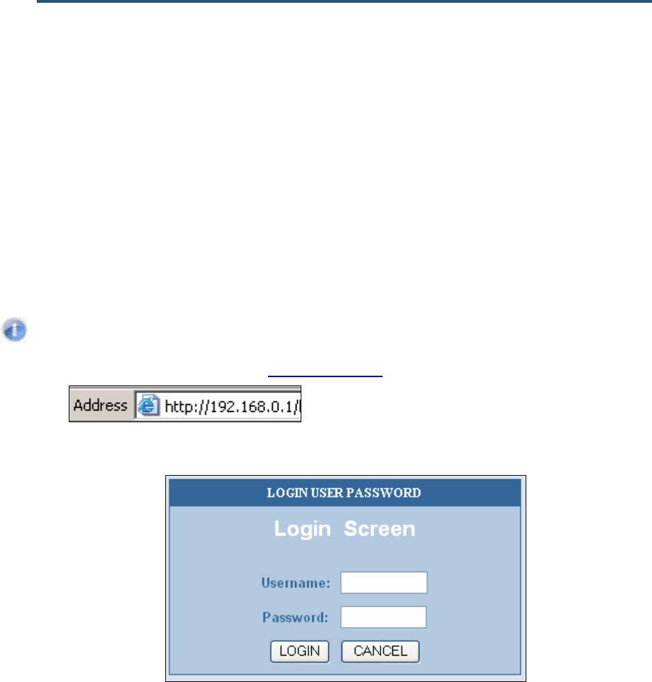
2. In the browser address bar, type http://192.168.0.1 and press the Enter key. For example:
The Login User Password screen appears (see Figure 17)
Figure 17. Login User Password Screen
3. In the Login User Password screen, enter the default administrator username and the
default administrator password provided by SMC Networks. Both the username and
password are case sensitive.
4. Click the Login button to access the Gateway. The Status page appears, showing
connection status information about the Gateway.
錯誤! 尚未定義樣式。
32
SMC8014WN and SMC8014WN2 Wireless Cable Modem Gateway Administrator Manual
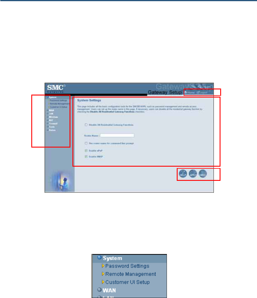
Understanding the Web Management Interface Screens
The left side of the management interface contains a menu bar you use to select menus for
configuring the Gateway. When you click a menu, information and any configuration settings
associated with the menu appear in the main area of the interface (see Figure 18). If the
displayed information exceeds what can be shown in the main area, scroll bars appear to
the right of the main area so you can scroll up and down through the information.
Figure 18. Example of Main Areas on the Web Management Interface
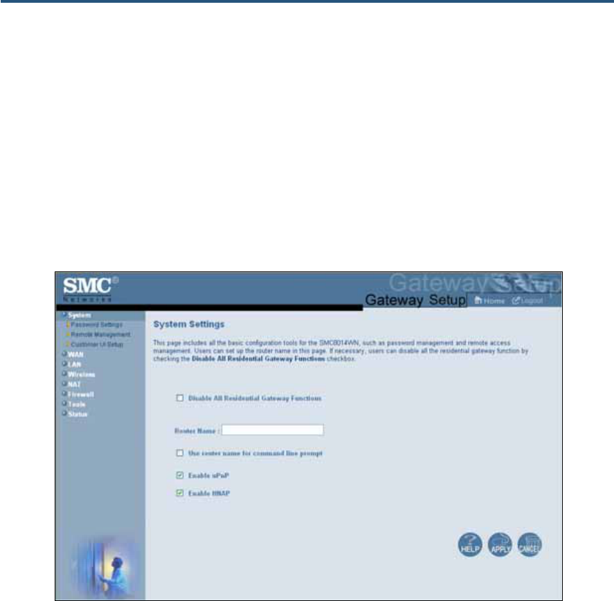
Some menus have submenus associated with them. If you click a menu that has submenus,
the submenus appear below the menu. For example, if you click the System menu, the
submenus Password Settings, Remote Management, and Customer UI Setup appear
below the System menu (see Figure 19).
Figure 19. Example of System Submenus
The top-right side of the page contains a Home button that displays the Home (Status) page
and a Logout button for logging out of the Web management interface.
Menu bar
Help, Apply, and
Cancel Buttons
Home and
Logout Buttons

錯誤! 尚未定義樣式。
33
SMC8014WN and SMC8014WN2 Wireless Cable Modem Gateway Administrator Manual
The bottom right side of the screen contains three buttons:
y Help displays online help
y Apply click this button to save your configuration changes to the displayed page
y Cancel click this button to discard any configuration changes made to the current page
Web Management Interface Menus and Submenus
Table 5 on the next page describes the menus and submenus in the Web management
interface. All of the menus, submenus, and pages are available with both the SMC8014WN
and SMC8014WN2 Gateways.
Note: The figures in this chapter show the model name SMC8014WN Gateway.
However, the same information applies to the SMC8014WN2 Gateway.

錯誤! 尚未定義樣式。
34
SMC8014WN and SMC8014WN2 Wireless Cable Modem Gateway Administrator Manual
Table 5. Web Management Interface Menus and Submenus
Menus and Submenus Description See Page
System Lets you disable all residential Gateway functions, define a router name, use the router
name at command prompts, and enable or disable UPnP and HNAP. Submenus let you: 35
System > Password Settings • Define user and admin password settings and idle timeout. 37
System > Remote Management • Allow users to manage the Gateway remotely using the Gateway’s Web interface and/or
Telnet, and enable or disable remote management of the Gateway’s administrator
interface.
39
System > Customer UI Setup • Select which configuration options on the Gateway’s user configuration menus are
shown to or hidden from users.
41
WAN Lets you configure Wide Area Network (WAN), renew or release DHCP WAN IP address,
and DNS address settings. The submenu lets you: 43
WAN > MAC Spoofing • Clone (“spoof”) the Gateway’s MAC address if necessary. 45
LAN Lets you configure settings for a private LAN,. The submenu lets you: 46
LAN > Ether Switch Control • Specify fixed-speed and duplex settings, and disable individual LAN ports. 48
Wireless Lets you configure basic wireless settings, set 802.11 mode, configure one or multiple
Service Set Identifier (SSID), and select the wireless channel. 50
NAT Provides the following submenu that lets you:
NAT > Port Forwarding • Configure predefined and customer port forwarding settings to let Internet users access
local services such as the Web Server or FTP server at your local site.
52
Firewall Lets you enable or disable the Gateway’s firewall. Submenus let you: 57
Firerwall > Access Control • Block traffic at the Gateway's LAN interfaces from accessing the Internet. 58
Firerwall > Special Application • Allow the firewall to open ports for outgoing and incoming sessions automatically for
multi-session protocols and applications.
62
Firerwall > URL Blocking • Block access to certain Web sites from local computers by entering either a full URL
address or keywords of the Web site.
65
Firerwall > Schedule Rule • Define schedule rules that work with the Gateway’s URL blocking feature. 68
Firerwall > Email/Syslog Alert • Send email notifications or add entries to the syslog when traffic is blocked, attempts
are made to intrude onto the network, and local computers try to access block URLs.
69
Firerwall > DMZ • Configure a local client computer for unrestricted two-way Internet access by defining it
as a Virtual DMZ host. 72
Tools Provides the following submenus with utilities for performing the following activities:
Tools > Configuration Tools Back up and restore Gateway configuration settings locally and remotely over the WAN,
and restore Gateway factory default settings. 73
Tools > Reboot Reboot the Gateway. 79
Tools > Diagnostics Perform trace route and ping diagnostic operations. 80
Status Shows the RG status; current time and system uptime; Internet, Gateway, and wireless
settings; network log; LAN client log; and cable modem system event log. The submenu
lets you:
84
Status > Cable Status • View cable initialization procedures, and cable downstream and upstream status. 86
錯誤! 尚未定義樣式。
35
SMC8014WN and SMC8014WN2 Wireless Cable Modem Gateway Administrator Manual
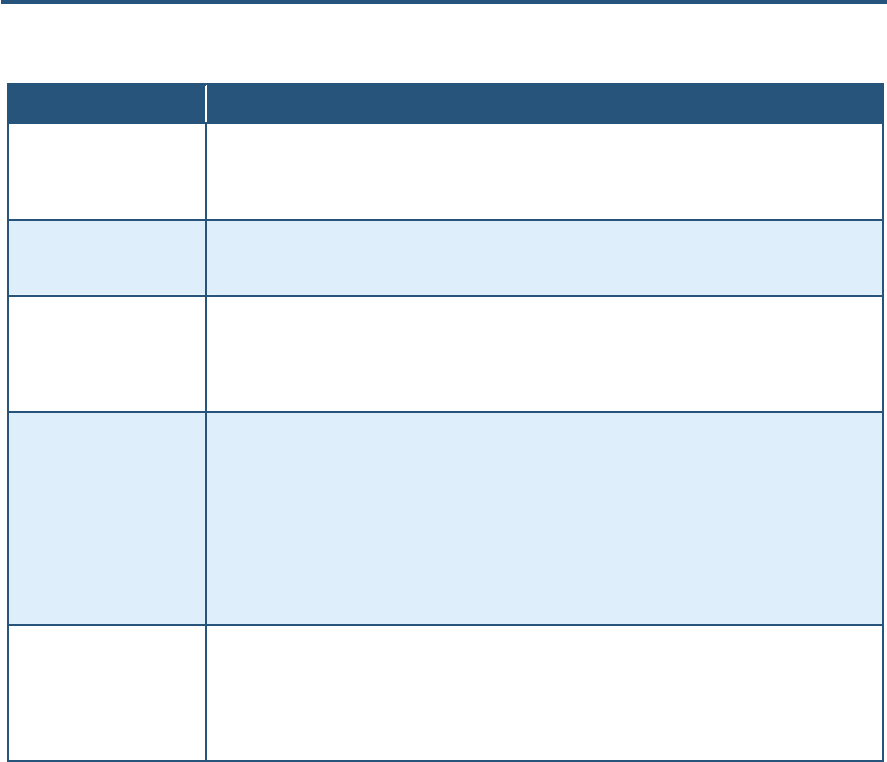
System Settings Menu
Path: System
The System Settings menu lets you:
y Enable or disable all residential Gateway functions
y Define the router name and enable it for use at a command-line prompt
y Enable or disable UPnP and HNAP
Figure 20. System Settings Menu
錯誤! 尚未定義樣式。
36
SMC8014WN and SMC8014WN2 Wireless Cable Modem Gateway Administrator Manual
Table 6. System Settings Menu Option
Option Description
Disable All Residential
Gateway Functions Enables or disables all residential Gateway functions.
• Checked = all residential Gateway functions are disabled.
• Unchecked = all residential Gateway functions are enabled. (default)
Router Name The name you want to assign to the Gateway. Assign a name so that this device will not be confused
with other devices on your wireless network. We recommend you use a name that is meaningful to you
so you can identify the Gateway easily.
Use router name for
command line prompt Determines whether the router name you specified appears in DOS command line prompts (for
example, if you Telnet into the Gateway).
• Checked = router name appears in command line prompts.
• Unchecked = router name does not appear in command line prompts. (default)
Enable UPnP Configures the Gateway as a Universal Plug and Play (UPnP) Internet gateway. UPnP allows for
dynamic connectivity between devices on a network. A UPnP-enabled device like the Gateway can
obtain an IP address, advertise its capabilities, learn about other connected UPnP devices and then
communicate directly with those devices. The same device can end its connection cleanly when it
wishes to leave the UPnP community. The intent of UPnP is to support zero-configuration, "invisible"
networking of devices including intelligent appliances, PCs, printers, and other smart devices using
standard protocols.
• Checked = UPnP is enabled on the Gateway. (default)
• Unchecked = UPnP is disabled on the Gateway.
Enable HNAP Configures the Gateway as a Home Network Administration Protocol (HNAP) device. HNAP allows the
Gateway to be configured and managed by remote entities, such as Network Magic or any software
application that discovers and manages network devices.
• Checked = HNAP is enabled on the Gateway.
• Unchecked = HNAP is disabled on the Gateway. (default)
錯誤! 尚未定義樣式。
37
SMC8014WN and SMC8014WN2 Wireless Cable Modem Gateway Administrator Manual
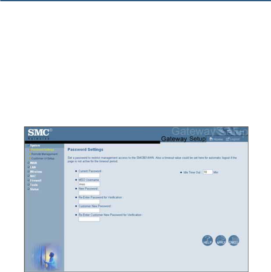
Password Settings Menu
Path: System > Password Settings
The Password Settings menu lets you change the following settings:
y Gateway default administrator username and password.
y Gateway default user’s password.
y Number of minutes of inactivity that can occur before your Web management session
times out automatically. The default setting is 10 minutes.
Figure 21. Password Settings Menu
錯誤! 尚未定義樣式。
38
SMC8014WN and SMC8014WN2 Wireless Cable Modem Gateway Administrator Manual
Table 7. Password Settings Menu Options
Option Description
Current Password Enter the current case-sensitive administrator password. For security purposes, every typed
character is masked with a dot (y). The default password is not shown for security purposes.
MSO Username Enter the current new case-sensitive administrator username.
New Password Enter the new case-sensitive administrator password you want to use. A password can
contain up to 32 alphanumeric characters. Spaces count as password characters. For security
purposes, every typed character is masked with a dot (y).
Re-Enter Password for Verification Enter the same case-sensitive administrator password you typed in the New Password field.
For security purposes, every typed character is masked with a dot (y).
Customer New Password Enter the new case-sensitive password your customers will use to log in to the Gateway Web
management interface. A password can contain up to 32 alphanumeric characters. Spaces
count as password characters. For security purposes, every typed character is masked with a
dot (y). If you leave this field blank, the default user password will be password.
Re-Enter Customer New Password
for Verification Enter the same case-sensitive user password you typed in the Customer New Password
field. For security purposes, every typed character is masked with a dot (y).
Idle Time Out Your Web management interface sessions timeout after 10 minutes of idle time. To change
this duration, enter a new timeout value.
錯誤! 尚未定義樣式。
39
SMC8014WN and SMC8014WN2 Wireless Cable Modem Gateway Administrator Manual
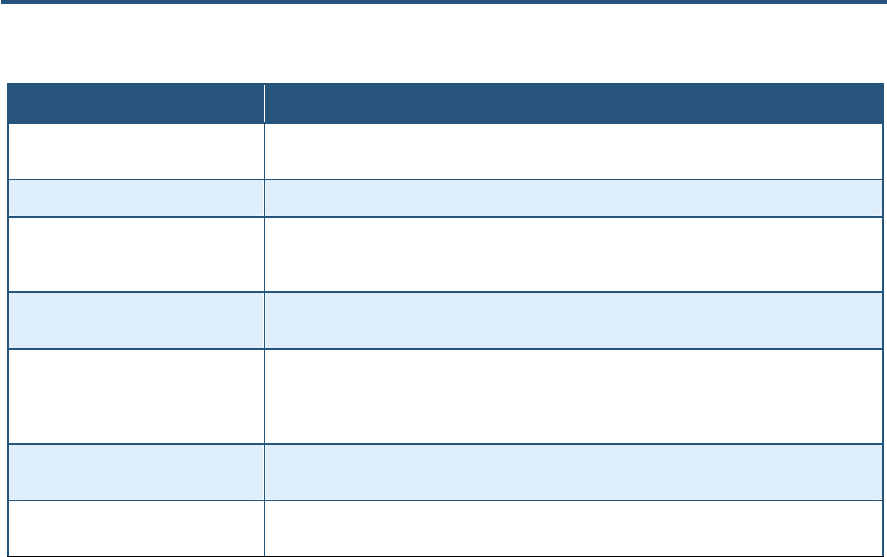
Remote Management Menu
Path: System > Remote Management
Administrative users can use the Gateway’s Web-based management or Telnet to manage
the device remotely using the public Internet.
y To use Web-based management, users specify the WAN IP address and remote
management port in the URL entered in the Browser’s address field.
y For Telnet, users specify the WAN IP address and the remote Telnet management port.
Using the Remote Management menu, you can enable HTTP, Telnet, HTTPS, and SSH and
specify the port numbers for each of these settings. You can also limit remote management
to specific IP addresses.
Figure 22. Remote Management Menu

錯誤! 尚未定義樣式。
40
SMC8014WN and SMC8014WN2 Wireless Cable Modem Gateway Administrator Manual
Table 8. Remote Management Settings Menu Options
Option Description
WAN IP Address Read-only screen that shows the IP address used to access the Gateway’s Web
management interface via the Internet. For example, if the WAN IP address is 123.45.67.8
and the Web management port is 8080, remote users type http://123.45.67.8:8080 to access
the Web management interface. To change the value shown, check the box to the right of this
option and enter a new value.
Http Port Port number used to access the Gateway’s Web management interface. Range is from 1024
to 65535. Default is 8080. To change the value shown, check the box to the right of this option
and enter a new value.
Telnet Port Port number used to Telnet into the Gateway. Range is from 1 to 65535. Default is 2323. To
change the value shown, check the box to the right of this option and enter a new value.
Https Port Port number used to access the Gateway via a secure HTTPS connection. Default is 8181.
To change the value shown, check the box to the right of this option and enter a new value.
SSH Port Port number used to access the Gateway via a Secure Sockets Shell (SSH) connection.
Default is 2222. To change the value shown, check the box to the right of this option and
enter a new value. Note that SSH enables access to the Command Line Interface (CLI). For
more information, refer to the CLI command documents provided separately.
Mso remote management Enables or disables remote access to administrator configuration options.
• Checked = administrator remote management is enabled. (default)
• Unchecked = administrator remote management is disabled.
Customer remote management Enables or disables remote access to user configuration options.
• Checked = user remote management is enabled.
• Unchecked = user remote management is disabled. (default)
Limit remote management to By default, enabling remote management makes the device available to all IP addresses.
To limit remote management to a subset of IP addresses, perform the following steps:
• Uncheck All IP Addresses.
• Select Single Address or Address Range from the drop-down list.
• Enter the IP address or address range in the fields.
• Click Add. The IP address pr address range appears in Permitted IP Addresses.
To delete an IP address or address range, perform the following steps. No precautionary
message appears before you delete an IP address.
• Click the address in Permitted IP Addresses.
• Click Delete.

錯誤! 尚未定義樣式。
41
SMC8014WN and SMC8014WN2 Wireless Cable Modem Gateway Administrator Manual
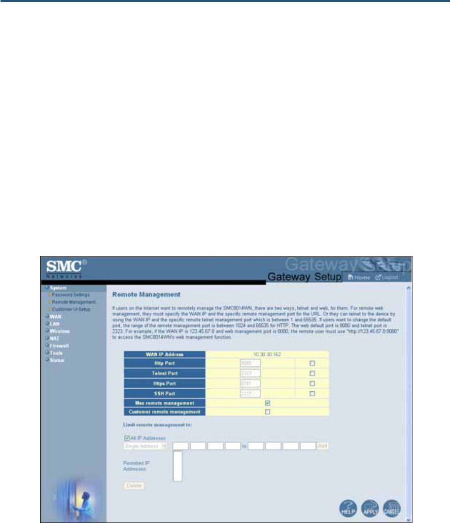
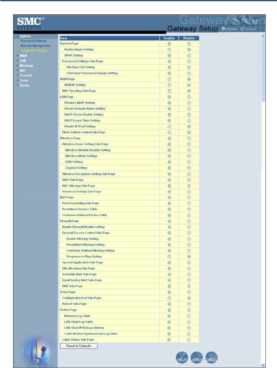
Customer UI Setup Menu
Path: System > Customer UI Setup
The Customer UI Setup menu lets you select which menus, submenus, and configuration
options are shown to (Enable) or hidden from (Disable) users. Using this menu, for example,
you can hide options that, if changed by users, could adversely affect the Gateway. These
settings do not affect the configuration options displayed for administrators.
A Reset to Defaults button at the bottom-left side of the menu lets you return the
parameters on this menu to their factory default settings.
錯誤! 尚未定義樣式。
42
SMC8014WN and SMC8014WN2 Wireless Cable Modem Gateway Administrator Manual
Figure 23. Sample Customer UI Setup Menu
錯誤! 尚未定義樣式。
43
SMC8014WN and SMC8014WN2 Wireless Cable Modem Gateway Administrator Manual
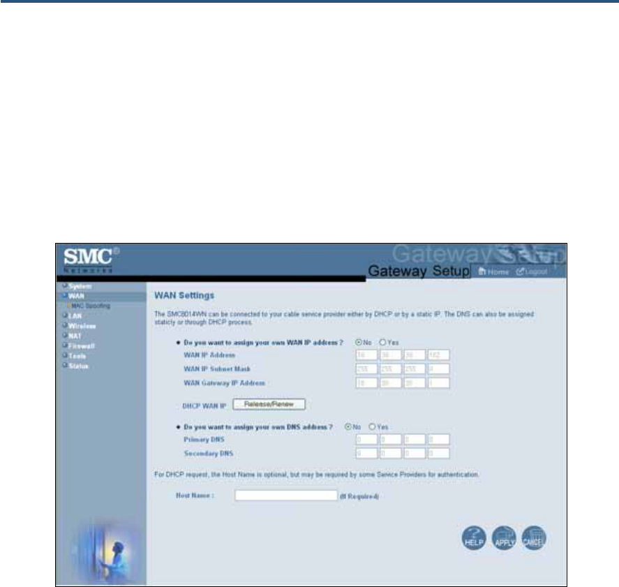
WAN Settings Menu
Path: WAN
The Gateway can connect to the cable service provider using either a static IP address or an
IP address automatically assigned by a Dynamic Host Configuration Protocol (DHCP) server.
Using the WAN Settings menu, you can assign your own static WAN IP and DNS addresses
to the Gateway. By default, both options are disabled, allowing the Gateway to obtain these
settings automatically from a DHCP server.
Figure 24. WAN Settings Menu
錯誤! 尚未定義樣式。
44
SMC8014WN and SMC8014WN2 Wireless Cable Modem Gateway Administrator Manual
Table 9. WAN Settings Menu Options
Option Description
Do you want to assign your own
WAN IP address? By default, this option is set to No. Cable modem providers typically use dynamic assignment
of IP addresses. To assign a static WAN IP address to the Gateway and make the WAN fields
below this option available, click Yes.
WAN IP Address Enter a unique static IP address the Gateway.
WAN IP Subnet Mask Enter the subnet mask for the Gateway.
WAN Gateway IP Address Enter the Gateway IP address.
DHCP WAN IP Release/Renew
button Click this button to release and then renew the Gateway’s IP address. This button is available
for DHCP only. It is unavailable when Do you want to assign your own WAN IP address is
set to Yes.
Do you want to assign your own
DNS address? By default, this option is set to No. Cable modem providers typically use dynamic assignment
of IP addresses. To assign your own IP addresses to primary and secondary DNS servers
and make the DNS fields below this option available, click Yes.
Primary DNS Enter a primary DNS server IP address.
Secondary DNS Enter the secondary DNS server IP address.
Host Name This setting is optional. If you will require a host name for DHCP requests, enter it here.
錯誤! 尚未定義樣式。
45
SMC8014WN and SMC8014WN2 Wireless Cable Modem Gateway Administrator Manual
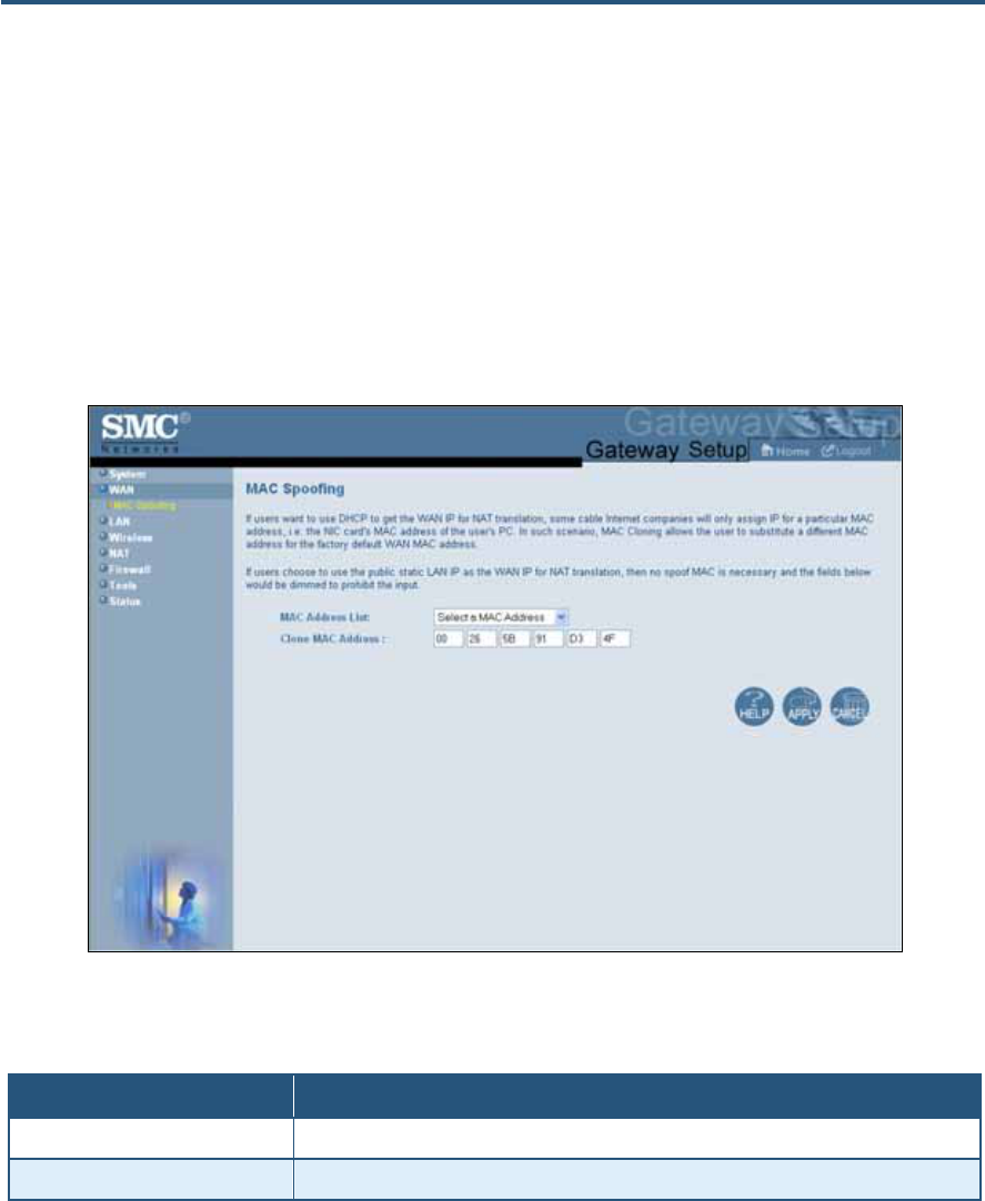
MAC Spoofing Menu
Path: WAN > MAC Spoofing
If you need to re-register your MAC address, use the MAC Spoofing menu to clone (or
“spoof”) the Gateway’s registered MAC address as necessary.
If you use the public static LAN IP address as the WAN IP for NAT translation, no MAC
spoofing is necessary.
Figure 25. MAC Spoofing Menu
Table 10. MAC Spoofing Menu Options
Option Description
MAC Address List Select the MAC address you want to spoof.
Clone MAC Address Clone the MAC address of the NIC communicating with the cable modem.
錯誤! 尚未定義樣式。
46
SMC8014WN and SMC8014WN2 Wireless Cable Modem Gateway Administrator Manual
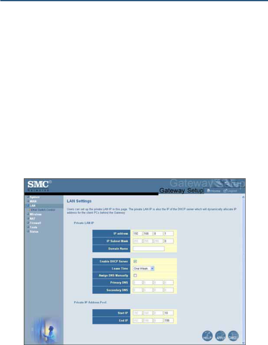
LAN Settings Menu
Path: LAN
IP addresses are close to being used up and thus very hard to get. One solution to this
problem is "private" IP addresses. Private IP addresses are ranges of IP addresses set
aside expressly for use by a company or other entity internally. Private IP addresses are
non-routable and, therefore, cannot be used to connect directly to the Internet.
Some of the advantages of private IP addresses include:
y Increased security, since private IP addresses are not routable across the Internet
y You conserve the world-wide pool of IP addresses
y You do not have to register or pay for these IP addresses in any way
The LAN Settings menu lets you configure private LAN IP settings and private IP address
pools for the Gateway.
Figure 26. LAN Settings Menu
錯誤! 尚未定義樣式。
47
SMC8014WN and SMC8014WN2 Wireless Cable Modem Gateway Administrator Manual
Table 11. LAN Settings Menu Options
Option Description
Pubic LAN IP
IP Address IP address of the Gateway’s private LAN settings. Default IP address is 192.168.0.1. if you
change this setting, the Gateway reboots after displaying a message.
IP Subnet Mask Subnet mask of the Gateway’s private LAN settings. Default subnet mask is 255.255.255.0.
Domain Name Domain name of the Gateway’s private LAN settings.
Enable DHCP Server Enables or disables the DHCP server to allow automatic allocation of IP addresses to LAN
client PCs.
• Checked = DHCP server is enabled. (default)
• Unchecked = DHCP server is disabled.
Lease Time Amount of time a DHCP network user is allowed connection to the Gateway with their current
dynamic IP address. Default is One Week. This option is available when Enable DHCP
Server is checked.
Assign DNS Manually Enables or disables the DHCP server to allow automatic allocation of primary and secondary
IP addresses for DSN servers on the LAN.
• Checked = use static IP addresses for primary and secondary DNS servers. If checked,
enter the IP addresses of the primary and secondary DNS server in the Primary DNS and
Secondary DNS fields.
• Unchecked = allocate IP addresses for primary and secondary DNS servers automatically.
(default)
Primary DNS Static IP address of the primary DNS server. This option is available when Assign DNS
Manually is checked.
Secondary DNS Static IP address of the secondary DNS server. This option is available when Assign DNS
Manually is checked.
Private IP Address Pool
Start IP Starting IP address range for the pool of allocated for private IP addresses.
End IP Ending IP address range for the pool of allocated for private IP addresses.
錯誤! 尚未定義樣式。
48
SMC8014WN and SMC8014WN2 Wireless Cable Modem Gateway Administrator Manual
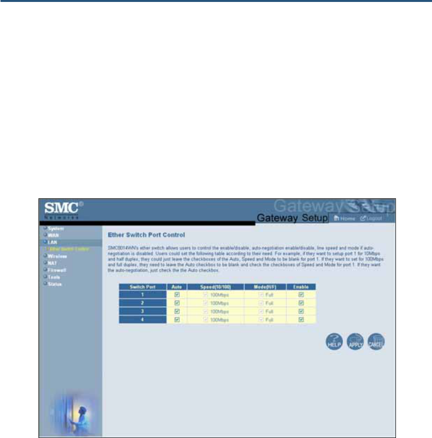
Ether Switch Port Control Menu
Path: LAN > Ether Switch Control
By default, the Gateway LAN ports are enabled to auto-negotiate the highest supported
speed and appropriate duplex mode. If these settings prevent the Gateway from
successfully connecting with other devices, you can use the Ether Switch Port Control menu
to configure the Gateway to use fixed speed and duplex settings. The Ether Switch Port
Control menu also let you disable the individual LAN ports. For your convenience, each port
can be configured independently of the other LAN ports on the Gateway.
Figure 27. Ether Switch Port Control Menu

錯誤! 尚未定義樣式。
49
SMC8014WN and SMC8014WN2 Wireless Cable Modem Gateway Administrator Manual
The following procedure describes how to change the settings in the Ether Switch Port
Control menu.
1. To change a port from auto-negotiation to a fixed speed and duplex setting:
a. Uncheck the Auto check box for the port.
b. Under Speed (10/100), click the radio button that corresponds to the fixed speed you
want to use for that port.
c. Under the Mode H/F column, leave the check mark for full-duplex mode or uncheck it
for half-duplex mode.
2. To disable a port, regardless of the auto-negotiation and duplex settings, uncheck Enable
for the port.
3. Click Apply.
錯誤! 尚未定義樣式。
50
SMC8014WN and SMC8014WN2 Wireless Cable Modem Gateway Administrator Manual
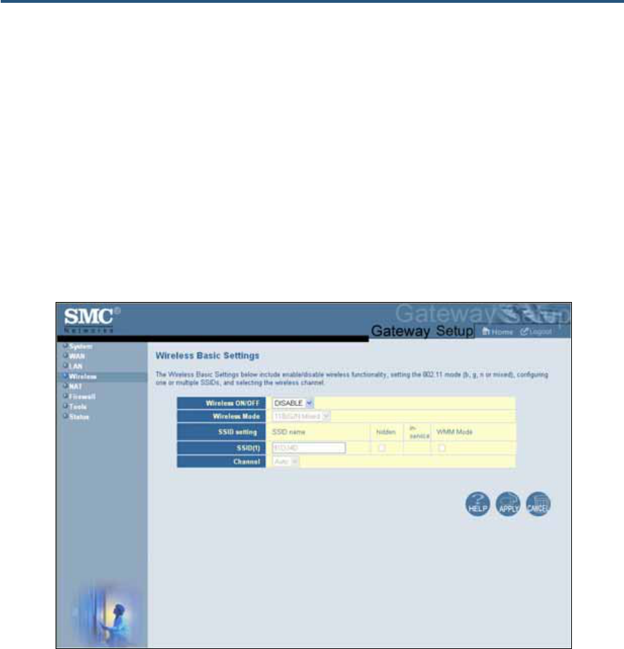
Wireless Basic Settings Menu
Path: Wireless
The Wireless Basic Settings menu lets you configure basic wireless settings, such as:
y Enabling or disabling the Gateway’s wireless operation
y Selecting an 802.11 wireless mode
y Configuring primary and multiple SSIDs
y Configuring channel settings
Figure 28. Wireless Basic Settings Menu

錯誤! 尚未定義樣式。
51
SMC8014WN and SMC8014WN2 Wireless Cable Modem Gateway Administrator Manual
Table 12. Wireless Basic Settings Menu Options
Option Description
Wireless ON/OFF Enables or disables the Gateway’s wireless operation.
• ENABLE = Gateway’s wireless operation is active. Selecting this option activates the options in this
menu. Clicking Apply displays the submenus below the Wireless menu.
• DISABLE = Gateway’s wireless operation is not active. Selecting this option deactivates the options in
this menu. Clicking Apply hides the submenus below the Wireless menu. (default)
Wireless Mode If wireless operation is enabled for the Gateway, this option selects the 802.11 wireless mode to be used
by the Gateway. Choices are:
• 11B/G Mixed = use this setting if you have a combination of IEEE 802.11b and IEEE 802.11g devices
on your network.
• 11B Only = use this setting if you have only IEEE 802.11b devices on your network or want to limit your
network to IEEE 802.11b devices.
• 11G Only = use this setting if you have only IEEE 802.11g devices on your network or want to limit your
network to IEEE 802.11g devices.
• 11N Only = use this setting if you have only IEEE 802.11n devices on your network or want to limit your
network to IEEE 802.11n devices.
• 11G/N Mixed = use this setting if you have a combination of IEEE 802.11g and IEEE 802.11n devices
on your network.
• 11B/G/N Mixed = use this setting if you have a combination of IEEE 802.11b, IEEE 802.11g, and IEEE
802.11n devices on your network. (default)
SSID setting SSID is the network name shared among all devices in a wireless network. The SSID must be identical for
all devices in the wireless network. It is case-sensitive and must not exceed 32 alpha-numeric characters,
which may be any keyboard character. Be sure these settings are the same for all devices in your wireless
network.
• Hidden = when checked, hides the SSID. Use this setting to block illegal connections. Users cannot
reconnect automatically or manually to a wireless network that uses a hidden SSID. The wireless
network that uses a hidden SSID does not appear in the Microsoft Windows Wireless Network
Connection window.
• In-service = when checked, broadcasts the Gateway’s SSID.
• WMM Mode = when checked, enables WMM functionality. Enabling WMM can help control latency and
jitter when transmitting multimedia content over a wireless connection.
Channel Select the appropriate channel from the list provided to correspond with your network settings, between 1
and 11 (in North America). Default is Auto, which selects the appropriate channel automatically. All
devices in your wireless network must use the same channel to work properly.
錯誤! 尚未定義樣式。
52
SMC8014WN and SMC8014WN2 Wireless Cable Modem Gateway Administrator Manual
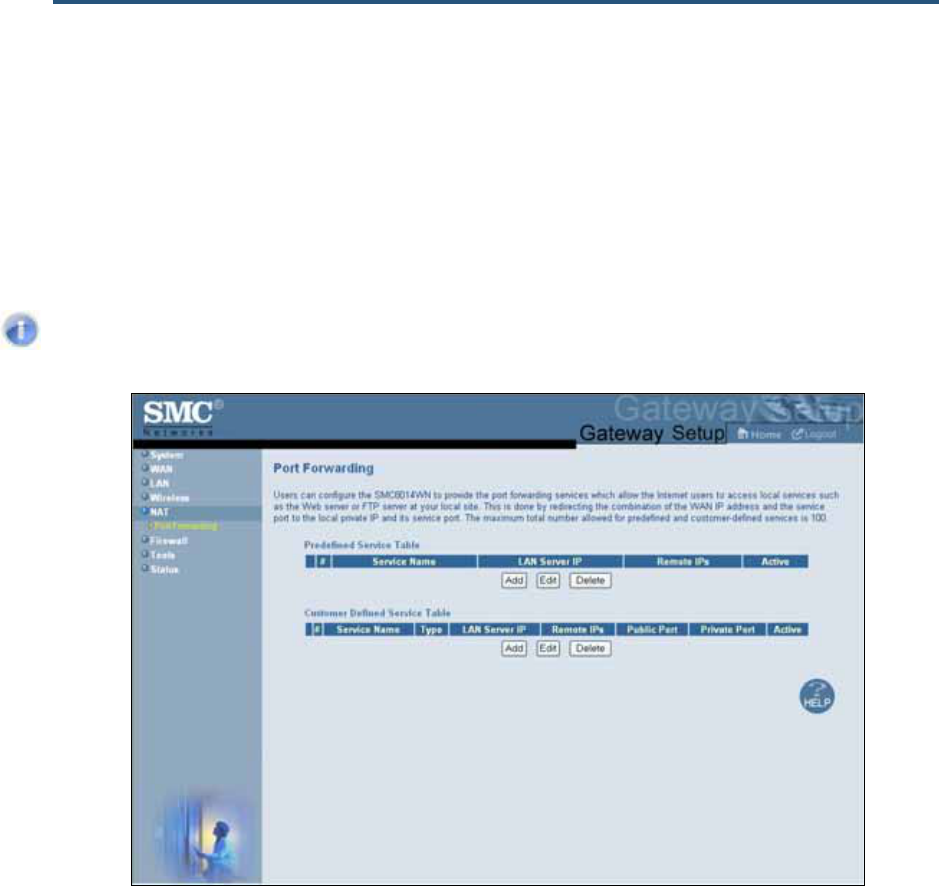
Port Forwarding Menu
Path: NAT > Port Forwarding
Using the Port Forwarding menu, you can configure the Gateway to provide port-forwarding
services that let Internet users access predefined services.
Note: If you change this setting, the Gateway reboots automatically.
Figure 29. Port Forwarding Menu
錯誤! 尚未定義樣式。
53
SMC8014WN and SMC8014WN2 Wireless Cable Modem Gateway Administrator Manual
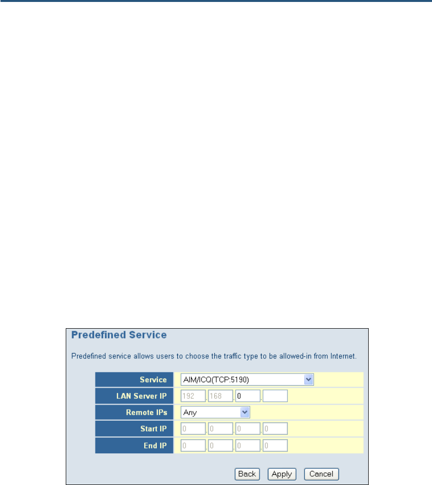
Adding Predefined Services
Using the following procedure, you can select well-known services and specify the LAN host
IP address(es) that will provide the service to the Internet.
1. In the Port Forwarding menu, click the Add button below the Predefined Service Table.
The Predefined Service menu appears (see Figure 30).
2. Complete the fields in the Predefined Service menu (see Table 13).
3. Click Apply. (Or click Back to return to the Port Forwarding menu or Cancel to cancel any
selections you made.) If you clicked Apply, the predefined service is added to the
Predefined Service Table on the Port Forwarding menu.
4. To configure additional predefined services (up to 100, including customer-defined
services), repeat steps 1 through 3.
5. To change the settings for a predefined service, click the radio button to the left of the
service in the Predefined Service Table and click the Edit button. When the Predefined
Service menu appears, edit the settings as necessary (see Table 13) and click Apply.
6. To delete a predefined service, click the radio button to the left of the service in the
Customer Defined Service Table and click the Delete button. No precautionary message
appears before you delete a predefined service.
Figure 30. Predefined Service Menu
錯誤! 尚未定義樣式。
54
SMC8014WN and SMC8014WN2 Wireless Cable Modem Gateway Administrator Manual
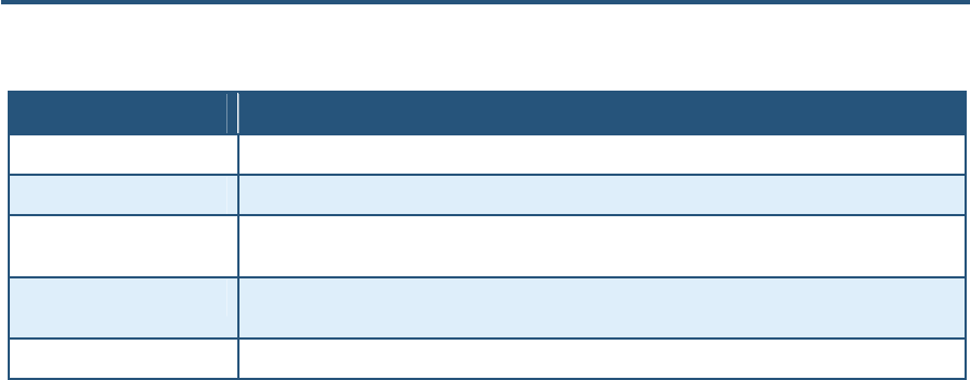
Table 13. Predefined Service Menu Options
Option Description
Service List of predefined services from which you can choose.
LAN Server IP Enter the last two octets of the IP address of the LAN PC or server running the service.
Remote IPs Select any remote IP address, a single remote IP address, or a range of remote IP addresses for the
defined service.
Start IP If Remote IPs is set to Single address or Address Range, enter the starting IP address of the
service.
End IP If Remote IPs is set to Address Range, enter the last octet in the ending IP address of the service.
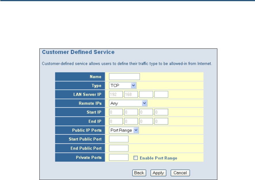
Adding Customer-Defined Services
Using the following procedure, you can define special application services you want to
provide to the Internet. The following example shows how to set port forwarding for a Web
server on an Internet connection, where port 80 is blocked from the WAN side, but port 8000
is available.
Name: Web Server
Type: TCP
LAN Server IP: 192.168.0.100
Remote IPs: Any (allow access to any public IP)
Public Port: 8000
Private Port: 80
With this configuration, all HTTP (Web) TCP traffic on port 8000 from any IP address on the
WAN side is redirected through the firewall to the Internal Server with the IP address
192.168.0.100 on port 80.
To create your own customized services:
1. In the Port Forwarding menu, click the Add button below the Customer Defined Service
Table. The Customer Defined Service page appears (see Figure 31).
2. Complete the fields in the Customer Defined Service page (see Table 14).
3. Click Apply. (Or click Back to return to the Port Forwarding menu or Cancel to cancel any
selections you made.) If you clicked Apply, the customer-defined service is added to the
Customer Defined Service Table on the Port Forwarding menu.
4. To configure additional customer-defined services (up to 100, including predefined
services), repeat steps 1 through 3.
5. To change the settings for a customer-defined service, click the radio button to the left of
the service in the Customer Defined Service Table and click the Edit button. When the
Customer Defined Service page appears, edit the settings as necessary (see Table 14)
and click Apply.
錯誤! 尚未定義樣式。
55
SMC8014WN and SMC8014WN2 Wireless Cable Modem Gateway Administrator Manual
6. To delete a customer-defined service, click the radio button to the left of the service in the
Customer Defined Service Table and click the Delete button. No precautionary message
appears before you delete a customized service.
Figure 31. Customer Defined Service Page
錯誤! 尚未定義樣式。
56
SMC8014WN and SMC8014WN2 Wireless Cable Modem Gateway Administrator Manual
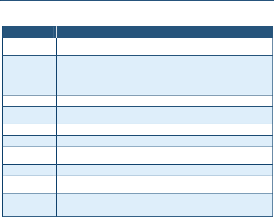
Table 14. Customer Defined Service Page Options
Option Description
Name Name for identifying the custom service. The name is for reference purposes only and should let you
identify this service from others you may define.
Type Type of protocol. Choices are:
• TCP (default)
• UDP
• TCP/UDP
LAN Server IP Enter the last two octets of the IP address of the LAN PC or server running the service.
Remote IPs Select any remote IP address, a single remote IP address, or a range of remote IP addresses for the
defined service.
Start IP If Remote IPs is set to Single address or Address Range, enter the starting IP address of the service.
End IP If Remote IPs is set to Address Range, enter the last octet in the ending IP address of the service.
Public IP Ports A single public IP port or a range of public IP ports on which the service is provided. If necessary, contact
the application vendor for this information.
Start Public Port Starting number of the port on which the service is provided.
End Public Port If Start Public Port is set to Port Range, enter the ending number of the port on which the service is
provided.
Private Ports Numbers of the ports whose traffic the Gateway forwards to the LAN. If there is a range of ports, enter the
starting private port here and check Enable Port Range. The Gateway automatically calculates the end
private port. The LAN PC server listens for traffic/data on this port (or these ports).
錯誤! 尚未定義樣式。
57
SMC8014WN and SMC8014WN2 Wireless Cable Modem Gateway Administrator Manual
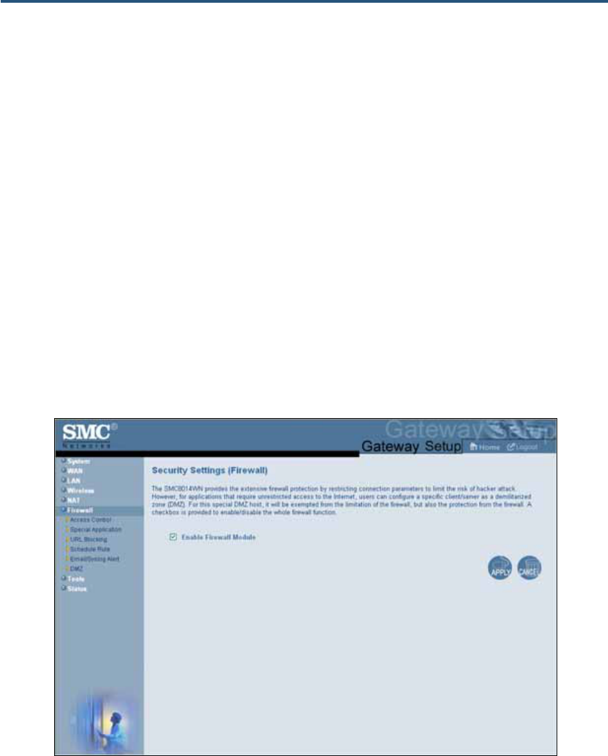
Security Settings (Firewall) Menu
Path: Firewall
The Security Settings (Firewall) menu lets you enable or disable the Gateway’s firewall. By
default, the Gateway’s firewall settings are enabled. To disable the firewall, uncheck Enable
Firewall Module and click Apply.
If you enable the Gateway firewall module, the following submenus appear in the menu bar:
y Access Control ⎯ see page 58
y Special Application ⎯ see page 62
y URL Blocking ⎯ see page 65
y Schedule Rule ⎯ see page 68
y Email/Syslog Alert ⎯ see page 69
y DMZ ⎯ see page 72
Figure 32. Security Settings (Firewall) Menu
錯誤! 尚未定義樣式。
58
SMC8014WN and SMC8014WN2 Wireless Cable Modem Gateway Administrator Manual
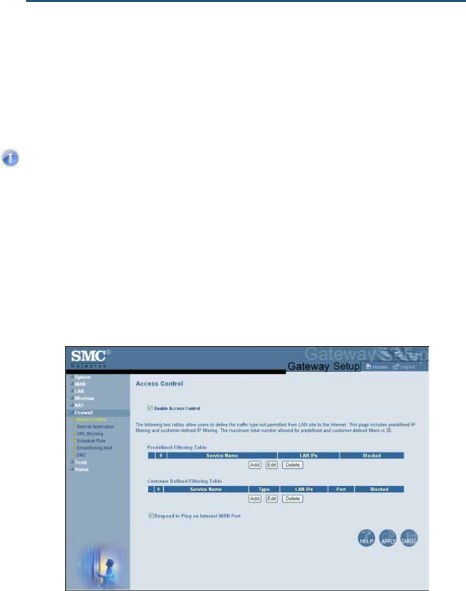
Access Control Menu
Path: Firewall > Access Control
The Access Control menu lets you enable access control to block traffic at the Gateway's
LAN interfaces from accessing the Internet.
Note: The Access Control submenu is not available in the menu bar if Enable
Firewall Module is disabled in the Security Settings (Firewall) menu (see page
57).
By default, the Gateway does not block attempts to access the LAN from the Internet. To
enable access control, check Enable Access Control if it is unchecked and click Apply.
When Access Control is enabled, you can define up to:
y 35 filters for traffic types not permitted from the LAN to the Internet.
y 35 predefined and customer-defined access rules for well-known services, or for other
services if you know the protocol and port number for the application.
A check box at the bottom of the menu lets you configure the Gateway to listen for or ignore
ping requests on the Gateway’s Internet WAN port.
Figure 33. Access Control Menu
錯誤! 尚未定義樣式。
59
SMC8014WN and SMC8014WN2 Wireless Cable Modem Gateway Administrator Manual
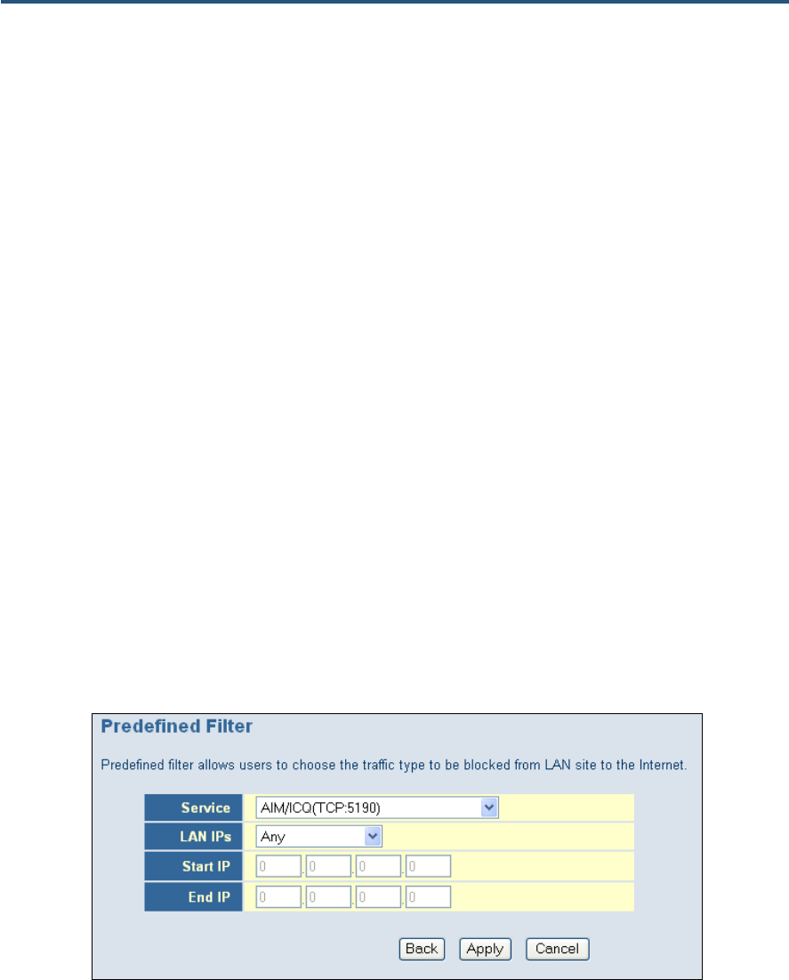
Adding Predefined Filters
The Gateway lets you select traffic you want to block from the LAN to the Internet.
1. In the Access Control menu, check Enable Access Control if it is not checked and click
the Apply button. The remaining fields in the menu become available.
2. Under Predefined Filtering Table, click the Add button. The Predefined Filter menu
appears (see Figure 34).
3. Complete the fields in the Predefined Filter menu (see Table 15).
4. Click Apply. (Or click Back to return to the Access Control menu or Cancel to cancel any
selections you made.) If you clicked Apply, the predefined filter is added to the Predefined
Filtering Table on the Access Control menu.
5. To define additional filters for access control (up to 35, including customer-defined filters),
repeat steps 1 through 4. When you finish, click Apply in the Access Control menu to save
your settings.
6. To change the settings for a predefined filter, click the radio button to the left of the service
in the Predefined Filtering Table and click the Edit button. When the Predefined Filter
menu appears, edit the settings as necessary (see Table 15) and click Apply. Click Apply
in the Access Control menu to save your settings.
7. To delete a predefined filter, click the radio button to the left of the filter in the Predefined
Filtering Table and click the Delete button. No precautionary message appears before
you delete a predefined filter. Click Apply in the Access Control menu to save your
settings.
Figure 34. Predefined Filter Menu
錯誤! 尚未定義樣式。
60
SMC8014WN and SMC8014WN2 Wireless Cable Modem Gateway Administrator Manual
Table 15. Predefined Filter Menu Options
Option Description
Service List of predefined services you can choose.
LAN IPs Select whether you want to apply the predefined filter to any LAN IP address, a single LAN IP
address, or a range of LAN IP addresses.
Start IP If LAN IPs is set to Single address or Address Range, enter the starting local IP address.
End IP If LAN IPs is set to Address Range, enter the last two octets in the ending local IP address.
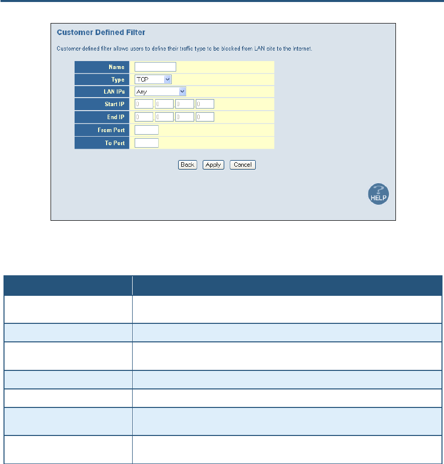
Adding Customer-Defined Filters
The Gateway lets you add customer-defined filters that block certain types of traffic from the
LAN side of the Gateway to the Internet side of the Gateway.
1. In the Access Control menu, check Enable Access Control if it is not checked and click
the Apply button. The remaining fields in the menu become available.
2. Under Customer Defined Filtering Table, click the Add button. The Customer Defined
Filter menu appears (see Figure 35).
3. Complete the fields in the Customer Defined Filter menu (see Table 16).
4. Click Apply. (Or click Back to return to the Access Control menu or Cancel to cancel any
selections you made.) If you clicked Apply, the customer-defined filter is added to the
Customer Defined Filtering Table on the Access Control menu.
5. To define additional filters for access control (up to 35, including predefined filters), repeat
steps 1 through 4. When you finish, click Apply in the Access Control menu to save your
settings.
6. To change the settings for a customer-defined filter, click the radio button to the left of the
filter in the Customer Defined Filtering Table and click the Edit button. When the
Customer Defined Filter menu appears, edit the settings as necessary (see Table 16) and
click Apply. Click Apply in the Access Control menu to save your settings.
7. To delete a customer-defined filter, click the radio button to the left of the filter in the
Customer Defined Filtering Table and click the Delete button. No precautionary
message appears before you delete a customer-defined filter. Click Apply in the Access
Control menu to save your settings.
錯誤! 尚未定義樣式。
61
SMC8014WN and SMC8014WN2 Wireless Cable Modem Gateway Administrator Manual
Figure 35. Customer Defined Filter Menu
Table 16. Customer Defined Filter Menu Options
Option Description
Name Name for identifying the custom filter. The name is for reference purposes only and should let
you identify this filter from others you may define.
Type The type of protocol you want to filter. Choices are TCP, UDP, and TCP/UDP. Default is TCP.
LAN IPs Select whether you want to apply the customer-defined filter to any LAN IP address, a single
LAN IP address, or a range of LAN IP addresses.
Start IP If LAN IPs is set to Single address or Address Range, enter the starting local IP address.
End IP If LAN IPs is set to Address Range, enter the last two octets in the ending local IP address.
From Port Enter the starting port number of the application you want to block. If necessary, obtain this
from the application vendor.
To Port Enter the ending port number of the application you want to block. If necessary, obtain this
from the application vendor.
Responding to or Ignoring WAN Port Pings
The bottom of the Access Control menu has a Respond to Ping on Internet WAN Port
check box.
y Checking this check box and clicking Apply configures the Gateway to respond to ping
requests on its Internet WAN port.
y Unchecking this check box and clicking Apply configures the Gateway to ignore ping
requests on its Internet WAN port.

錯誤! 尚未定義樣式。
62
SMC8014WN and SMC8014WN2 Wireless Cable Modem Gateway Administrator Manual
Special Application Menu
Path: Firewall > Special Application
Using the Special Application menu, you can configure the Gateway to detect multiple-
session applications and allow them to pass through the firewall.
For special applications, besides the initial communication session, there are multiple related
sessions created during the protocol communications. Normally, a normal treats the
triggered sessions as independent sessions and blocks them. However, the Gateway can
co-relate the triggered sessions with the initial session and group them together in the NAT
session table. As a result, you need only specify which protocol type and port number you
want to track, as well as some other related parameters. In this way, the Gateway can pass
the special applications according to the supplied information.
Assume, for example, that to use H.323 in a Net Meeting application, a local client starts a
session A to a remote host. The remote host uses session A to communicate with the local
host, but it also could initiate another session B back to the local host. Since there is only
session A recorded in the NAT session table when the local host starts the communication,
session B is treated as an illegal access from the outside and is blocked. Using the Special
Application menu, you can configure the Gateway to co-relate sessions A and B and
automatically open the port for the incoming session B.
The maximum allowed triggers is 50. To enable the special application function, check the
Enable Triggering checkbox and click Apply. To disable it, uncheck the Enable Triggering
checkbox and click Apply.
Note: The Special Application submenu is not available in the menu bar if
Enable Firewall Module is disabled in the Security Settings (Firewall) menu (see
page 57).
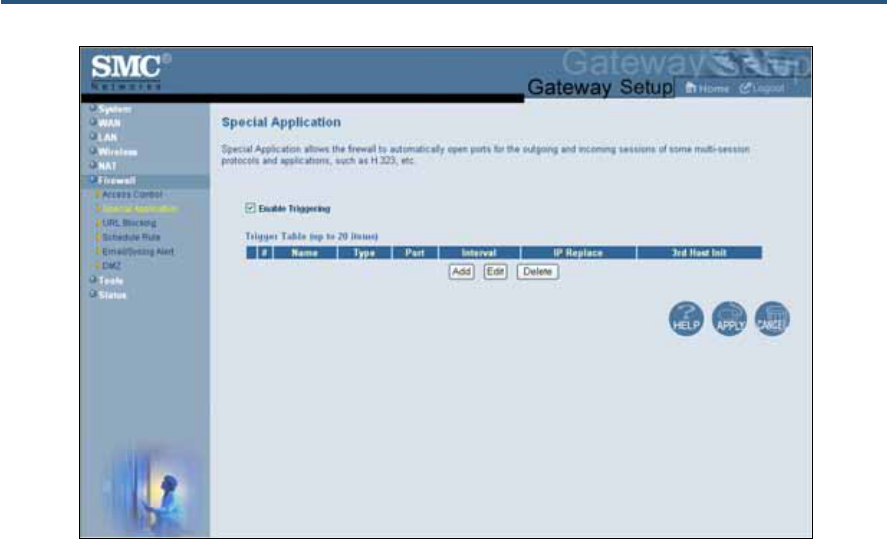
錯誤! 尚未定義樣式。
63
SMC8014WN and SMC8014WN2 Wireless Cable Modem Gateway Administrator Manual
Figure 36. Special Application Menu
To enable port triggering:
1. In the Special Application menu, check Enable Triggering if it is unchecked and click the
Apply button. The Trigger Table becomes available.
2. Click the Add button below Trigger Table. The Trigger menu appears (see Figure 37).
3. Complete the fields in the Trigger menu (see Table 17).
4. Click Apply. (Or click Back to return to the Trigger menu or Cancel to cancel any
selections you made.) If you clicked Apply, the trigger is added to the Trigger Table on
the Special Application menu.
5. To configure additional triggers (up to 20), repeat steps 1 through 4. When you finish, click
Apply in the Special Application menu to save your settings.
6. To change the settings for a trigger, click the radio button to the left of the trigger in the
Trigger Table and click the Edit button. When the Trigger menu appears, edit the settings
as necessary (see Table 17) and click Apply. Click Apply in the Special Application menu
to save your settings.
7. To delete a trigger, click the radio button to the left of the trigger in the Trigger Table and
click the Delete button. No precautionary message appears before you delete a trigger.
Click Apply in the Special Application menu to save your settings.
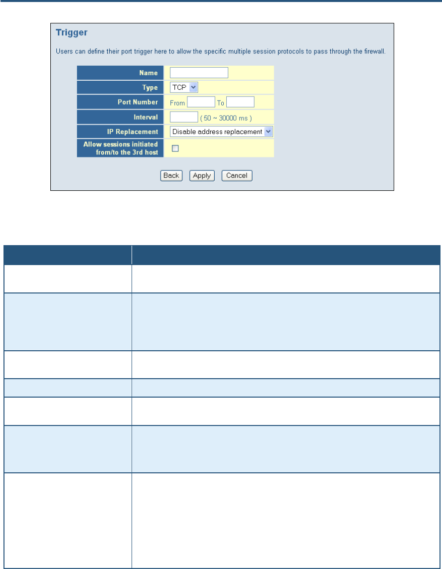
錯誤! 尚未定義樣式。
64
SMC8014WN and SMC8014WN2 Wireless Cable Modem Gateway Administrator Manual
Figure 37. Trigger Menu
Table 17. Trigger Menu Options
Option Description
Name Name for identifying the trigger. The name is for reference purposes only and should let you
identify this trigger from others you may define..
Type The type of protocol you want to use with the trigger. For example, to track the H.323
protocol, the protocol type should be TCP. Choices are:
• TCP (default)
• UDP
Port Number From and To port ranges of the special application. For example, to track the H.323 protocol,
the From and To ports should be 1720.
Target Port From and To port ranges for the target port listening for the special application.
Interval Interval between 50 and 30000 between two continuous sessions. If the interval exceeds this
time interval setting, the sessions are considered to be unrelated.
IP Replacement Select the IP replacement according to the application. Some applications embed the source
host's IP in the datagram that prevent NATs from translating the IP address in the datagram.
To make sure the network address translation is complete, IP replacement is necessary for
these special applications, such as H.323.
Allow sessions initiated from/to the
3rd host Enable (check) or disable (uncheck) sessions to be initiated from or to a third host. To prevent
hacker attacks from a third host, this feature usually is disabled (not checked). However,
some special applications, such as MGCP in a VOIP application, permit a session initiated
from a third host. For example, assume Client A is trying to make a phone call to host B.
Client A tries to communicate with the Media Gateway Controller (MGC) first and provides
host B's number to MGC. The MGC checks its own database to find B and communicates
with B to provide B the information about A. B uses this information to communicate directly to
A. So initially, A is talking to MGC, but the final step has B initiating a session to A. If the third-
party host-initiated session is not allowed in this example, the whole communication fails.

錯誤! 尚未定義樣式。
65
SMC8014WN and SMC8014WN2 Wireless Cable Modem Gateway Administrator Manual
URL Blocking Menu
Path: Firewall > URL Blocking
Using the URL Blocking menu, you can configure the Gateway to block access to certain
Web sites from local computers by entering either a full URL address or keywords of the
Web site. The Gateway examines all the HTTP packets to block the access to those
particular sites. This feature can be used to protect children from accessing inappropriate
Web sites. You can block up to 50 sites.
Using URL blocking, you can also make up to 10 computers exempt from URL blocking and
have full access to all Web sites at any time.
Note: The URL Blocking submenu is not available in the menu bar if Enable
Firewall Module is disabled in the Security Settings (Firewall) menu (see page
57).
Tip: The Gateway provides a Schedule Rules feature that lets you configure URL
blocking for certain days, if desired. For more information, see “Schedule Rule” on
page 68.
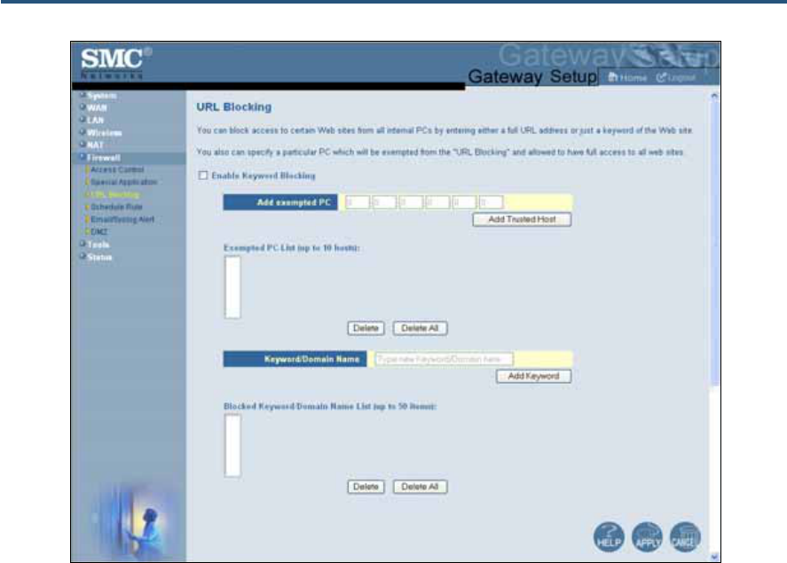
錯誤! 尚未定義樣式。
66
SMC8014WN and SMC8014WN2 Wireless Cable Modem Gateway Administrator Manual
Figure 38. URL Blocking Menu
Enabling URL Blocking
To enable URL blocking:
1. In the URL Blocking menu, check Enable Keyword Blocking if it is not checked and click
Apply.
2. To exempt a computer from URL blocking, enter the computer’s MAC address in the Add
exempted PC field and click the Add Trusted Host button. The MAC address you entered
appears in the Exempted PC List.
3. Repeat step 2 for each additional computer (up to 10) you want to exempt from URL
blocking.
4. To remove a computer from being exempted, click it in the Exempted PC List and click
Delete. A precautionary message does not appear before the deletion.
5. To remove all computers from being exempted, click Delete All. A precautionary message
does not appear before the deletion.
6. Click Apply.
7. To define the days and times when URL blocking is enforced, see “Schedule Rule” on
page 68.

錯誤! 尚未定義樣式。
67
SMC8014WN and SMC8014WN2 Wireless Cable Modem Gateway Administrator Manual
Blocking Sites
To block a site:
1. Click in the Keyword/Domain Name field, enter a keyword or the domain name of the site
you want to block, and click Add Keyword. The keyword or domain name appears in
Blocked Keyword/Domain List.
2. Repeat step 2 for each additional keyword or domain (up to 50) you want to make exempt
from URL blocking.
3. To remove one keyword or domain from being blocked, click it in the Blocked
Keyword/Domain List and click Delete. A precautionary message does not appear before
the deletion.
4. To remove all keywords and domains from being blocked, click Delete All. A precautionary
message does not appear before the deletion.
5. Click Apply.
6. To define the days and times when URL blocking is enforced, see “Schedule Rule” on
page 68.
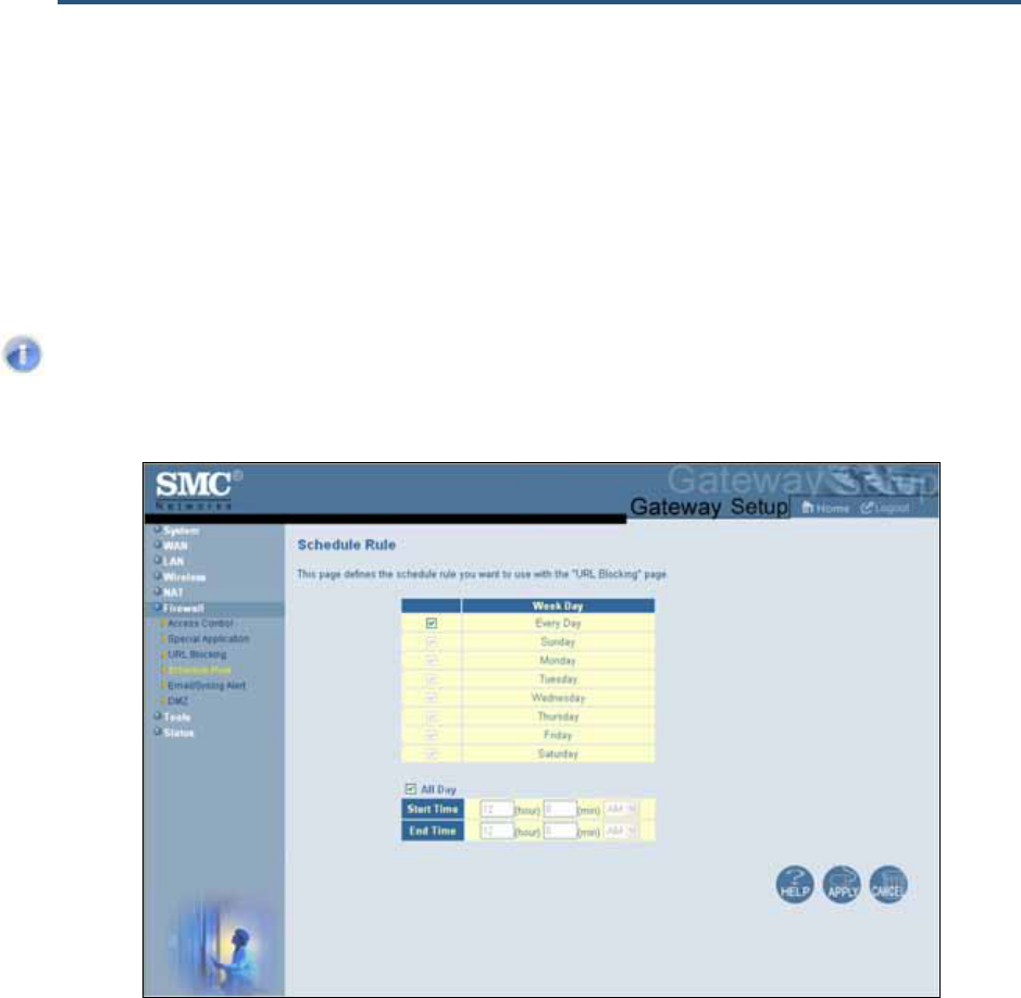
錯誤! 尚未定義樣式。
68
SMC8014WN and SMC8014WN2 Wireless Cable Modem Gateway Administrator Manual
Schedule Rule Menu
Path: Firewall > Schedule Rule
Schedule rules work with the Gateway’s URL blocking feature (described on page 65) to tell
the Gateway when to perform URL blocking.
Note: The Schedule Rule submenu is not available in the menu bar if Enable
Firewall Module is disabled in the Security Settings (Firewall) menu (see page
57).
Figure 39. Schedule Rule Menu
By default, the Gateway is configured to apply URL blocking 24 hours every day. To change
this setting:
1. To change the days when URL blocking is in force, uncheck Every Day under Week Day.
Then check the days when you want to apply schedule rules to URL blocking.
2. To change the hours when URL blocking is in force, uncheck All Day. Then specify the
start and end times when you want to apply schedule rules to URL blocking. Select AM or
PM, where AM refers to times from Midnight to Noon and PM refers to times from Noon to
Midnight.
3. Click Apply.

錯誤! 尚未定義樣式。
69
SMC8014WN and SMC8014WN2 Wireless Cable Modem Gateway Administrator Manual
Email/Syslog Alert Menu
Path: Firewall > Email/Syslog Alert
The Gateway inspects packets at the application layer, and stores TCP and UDP session
information, including timeouts and number of active sessions. This information is helpful
when detecting and preventing Denial of Service (DoS) and other network attacks.
If you enabled the Gateway’s firewall or content-filtering feature, you can use the
Email/Syslog Alert menu to have the Gateway send email notifications and/or add entries to
the syslog when:
y Traffic is blocked
y Attempts are made to intrude onto the network
y Local computers try to access block URLs
The Email/Syslog Alert menu has three sections for specifying email and syslog settings:
y The top section lets you define the email settings.
y The middle section lets you specify the address of the syslog server.
y The bottom section lets you enable or disable email alerts and/or add syslog entries.
Note: The Email/Syslog Alert submenu is not available in the menu bar if Enable
Firewall Module is disabled in the Security Settings (Firewall) menu (see page
57).
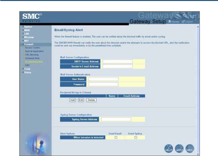
錯誤! 尚未定義樣式。
70
SMC8014WN and SMC8014WN2 Wireless Cable Modem Gateway Administrator Manual
Figure 40. Email/Syslog Alert Menu
Configuring Email Alerts
The following procedure describes how to configure the Gateway to send email notifications
when it detects intrusion attempts. This procedure assumes that your mail server is working
properly.
1. In the Email/Syslog Alert menu, under Mail Server Configuration, enter the following
information:
– SMTP Server Address = IP address of the SMTP server that will forward the email
notification to recipients.
– Sender’s Email Address = name that will appear as the sender in the email
notifications.
2. Under Mail Server Authentication, enter the following information:
– User Name = your email name.
– Password = your email password. For security, each typed character is masked with
a dot (y).
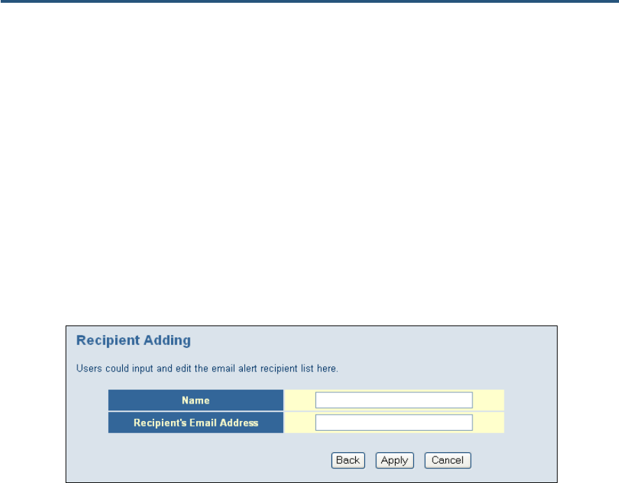
錯誤! 尚未定義樣式。
71
SMC8014WN and SMC8014WN2 Wireless Cable Modem Gateway Administrator Manual
3. Under Recipient list, click Add. When the Recipient Adding menu appears (see Figure
41), enter the name of the person who will receive email notifications and the person’s
email address, and then click Apply. (Or click Back to return to the Email/Syslog Alert
menu or Cancel to cancel any selections you made.) If you clicked Apply, the email
account is added to the Recipient list on the Email/Syslog Alert menu. To send email to
additional email accounts (up to 4), repeat this step.
4. To change the settings for an email recipient, click the radio button to the left of the
recipient in the Recipient list and click the Edit button. When the Recipient Adding menu
appears, edit the settings as necessary and click Apply.
5. To delete an email recipient, click the radio button to the left of the recipient and click
Delete. No precautionary message appears before you delete the email recipient.
6. Click Apply.
Figure 41. Recipient Adding Menu
Configuring Syslog Entries
To configure the Gateway to add syslog entries when it detects intrusion attempts:
1. In the Email/Syslog Alert menu, under Syslog Server Configuration, enter the syslog
server address in the Syslog Server Address field.
2. Click Apply.
Configuring Alert Options
After configuring email notifications and/or syslog entries, use the check boxes under Alert
Options to enable email notifications and/or syslog entries.
1. To enable email notifications, check Send Email next to When intrusion is detected.
2. To enable syslog entries, check Send Syslog next to When intrusion is detected.
3. Click Apply.
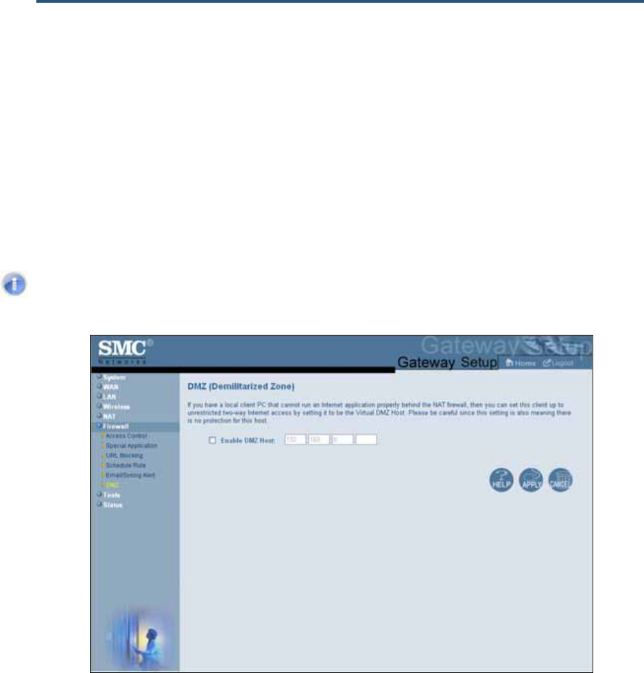
錯誤! 尚未定義樣式。
72
SMC8014WN and SMC8014WN2 Wireless Cable Modem Gateway Administrator Manual
DMZ (Demilitarized Zone) Menu
Path: Firewall > DMZ
If you have a local client computer that cannot run an Internet application properly behind
the NAT firewall, configure it for unrestricted two-way Internet access by defining it as a
Virtual Demilitarized Zone (DMZ) host in the DMZ (Demilitarized Zone) menu. Adding a
client to the DMZ may expose your local network to security risks because the client in the
DMZ is not protected by the firewall.
Note: The DMZ submenu is not available in the menu bar if Enable Firewall
Module is disabled in the Security Settings (Firewall) menu (see page 57).
Figure 42. DMZ (Demilitarized Zone) Menu
To configure DMZ settings:
1. In the DMZ (Demilitarized Zone) menu, check Enable DMZ Host. The 2 rightmost fields
next to this option become available.
2. Enter the last two octets in the IP address of the computer to be used as the DMZ server.
3. Click Apply.
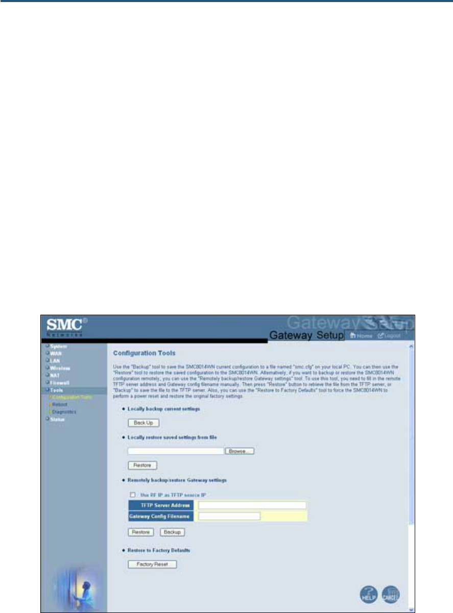
錯誤! 尚未定義樣式。
73
SMC8014WN and SMC8014WN2 Wireless Cable Modem Gateway Administrator Manual
Configuration Tools Menu
Path: Tools > Configuration Tools
Gateways often get upgraded or swapped out for a number of reasons. There also times
when a Gateway might fail. In such cases, having a backup file containing your configuration
settings allows you to restore a configuration by importing the configuration settings back
into the Gateway.
Using the Configuration Tools menu, you can:
y Back up the Gateway’s current configuration settings locally. See page 74.
y Restore the configuration settings locally from a back-up copy. See page 75.
y Remotely back up the current configuration settings over the WAN. See page 76.
y Remotely restore the configuration settings from a backup copy over the WAN. See
page 76.
y Restore the Gateway’s factory default settings. See page 77.
Figure 43. Configuration Tools Menu
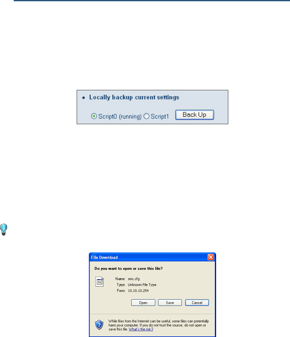
錯誤! 尚未定義樣式。
74
SMC8014WN and SMC8014WN2 Wireless Cable Modem Gateway Administrator Manual
Backing Up the Gateway’s Current Configuration Locally
To back up the Gateway’s current configuration locally:
1. If one or more scripts appear to the left of the Back Up button under Locally backup
current settings, click the script you want to back up. (running) appears next to the script
that is currently running.
2. Click the Back Up button.
3. When the File Download dialog box appears (see Figure 44), click Save. (Or click Open to
view the file prior to saving it. If you open the file, you will have to repeat steps 1 and 2 to
save it.)
4. When the Save As dialog box appears, go to the location where you want to save the
configuration file and click the Save button. The file is saved as smc.cfg.
5. When the save operation is complete, the Download complete dialog box appears (see
Figure 45). Click Open to open the configuration file, Open Folder to open the folder
containing the configuration file, or Close to close the dialog box.
Tip: If you click Open and a message tells you that an application could not be
found to open the configuration file, open the file in a text editor such as WordPad.
Figure 44. File Download Dialog Box
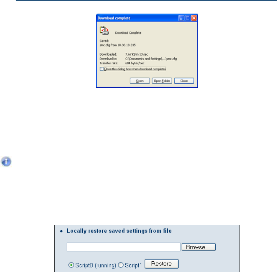
錯誤! 尚未定義樣式。
75
SMC8014WN and SMC8014WN2 Wireless Cable Modem Gateway Administrator Manual
Figure 45. Download Complete Dialog Box
Restoring the Gateway’s Current Configuration Locally
If you backed up the Gateway’s configuration settings locally, use the following procedure to
restore the settings locally.
Note: Restoring the Gateway’s settings from a configuration file erases all of the
Gateway’s current settings.
1. If one or more scripts appear to the left of the Restore button under Locally restore
saved settings from file, click the script you want to restore. (running) appears next to
the script that is currently running.
2. Click the Browse button.
3. When the Choose File dialog box appears, go to the location where you saved the
smc.cfg file. Then either double-click the file, or click it and click the Open button. The file
path and name appear to the left of the Browse button.
4. Click the Restore button. The message in Figure 46 appears.
5. Click OK to override the Gateway’s current configuration with the one in the configuration
file or click Cancel to not restore the configuration from the file.
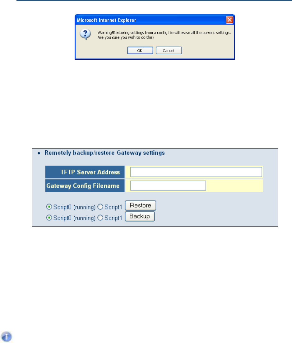
錯誤! 尚未定義樣式。
76
SMC8014WN and SMC8014WN2 Wireless Cable Modem Gateway Administrator Manual
Figure 46. Warning Message when Restoring from a Configuration File
Backing Up the Gateway’s Current Configuration Remotely
You can back up the Gateway’s current configuration remotely by uploading the smc.cfg
file to a TFTP server.
1. Under Remotely backup/restore Gateway settings, enter the IP address of the TFTP
server in the TFTP Server Address field.
2. In the Gateway Config Filename field, enter the name of the configuration file.
3. If one or more scripts appear to the left of the Backup button, select the script you want to
back up. (running) appears next to the script that is currently running.
4. Click the Backup button.
Restoring the Gateway’s Current Configuration Remotely
If you backed up the Gateway’s configuration settings to a TFTP server, use the following
procedure to restore the settings remotely.
Note: Restoring the Gateway’s settings from a configuration file erases all of the
Gateway’s current settings.
1. Under Remotely backup/restore Gateway settings, enter the IP address of the TFTP
server in the TFTP Server Address field where the SMC configuration file you want to
restore is located.
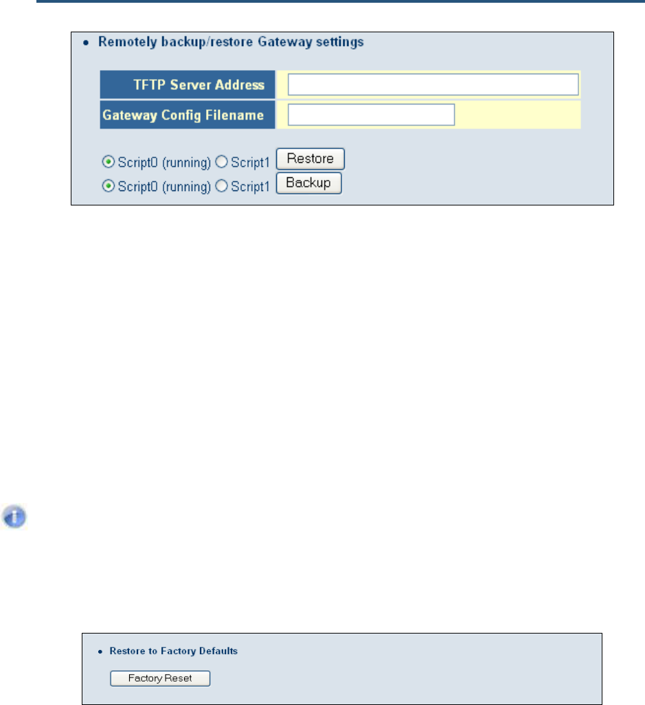
錯誤! 尚未定義樣式。
77
SMC8014WN and SMC8014WN2 Wireless Cable Modem Gateway Administrator Manual
2. In the Gateway Config Filename field, enter the name of the configuration file.
3. If one or more scripts appear to the left of the Restore button, select the script you want to
restore. (running) appears next to the script that is currently running.
4. Click the Restore button. The message in Figure 46 appears.
5. Click OK to override the Gateway’s current configuration with the one in the configuration
file or click No to not restore the configuration from the file.
Restoring Factory Defaults
One way to restore the Gateway’s factory default settings is to use the Reset switch on the
Gateway’s rear panel (see “Restoring Factory Defaults” on page 15). Another way is to use
the Configuration Tools menu to power-cycle the Gateway.
Note: Rebooting the Gateway removes any customized overrides you made to the
default settings. To reboot the Gateway and retain any customized settings, use
the Reboot menu (see “Reboot Menu“ on page 79).
1. Under Restore to Factory Defaults, click Factory Reset. The warning message in Figure
47 appears.
2. Click OK to restore the Gateway’s factory default settings or click Cancel to retain the
Gateway’s current settings.
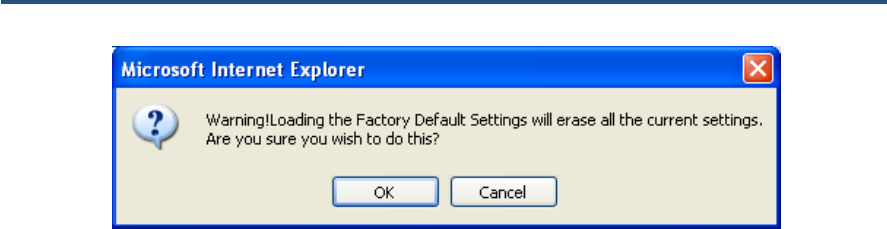
錯誤! 尚未定義樣式。
78
SMC8014WN and SMC8014WN2 Wireless Cable Modem Gateway Administrator Manual
Figure 47. Warning Message when Restoring Factory Defaults
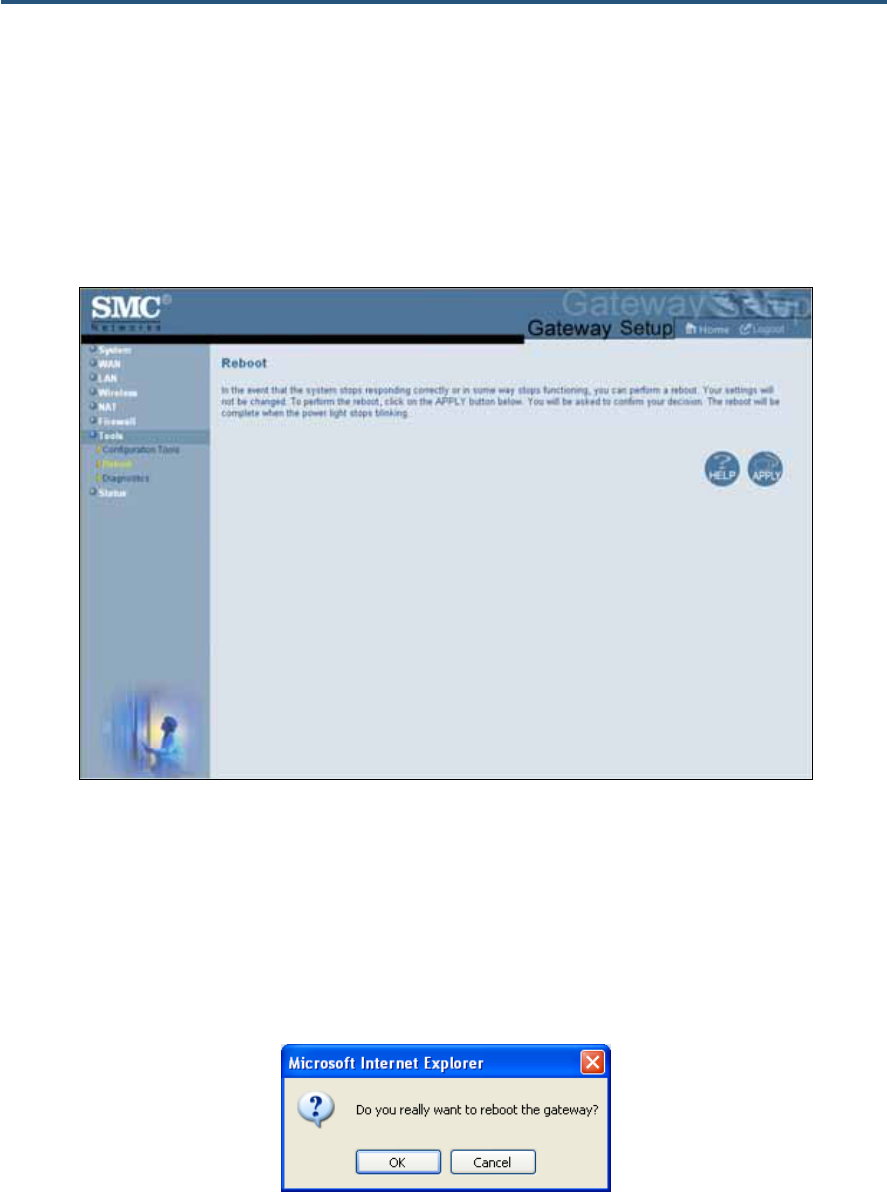
錯誤! 尚未定義樣式。
79
SMC8014WN and SMC8014WN2 Wireless Cable Modem Gateway Administrator Manual
Reboot Menu
Path: Tools > Reboot
Using the Reboot menu, you can reset the Gateway and retain all changes that have been
made to the Gateway’s factory default settings.
Figure 48. Reboot Menu
To reboot the Gateway and retain all changes made to its factory default settings:
1. In the Reboot menu, click Apply. The precautionary message in Figure 49 appears.
2. Click OK to reboot the Gateway or click Cancel to not reboot it. If you clicked OK, the
reboot is complete when the Power LED on the front panel of the Gateway stops blinking.
You will need to log in to the Web interface again.
Figure 49. Precautionary Message When Rebooting the Gateway
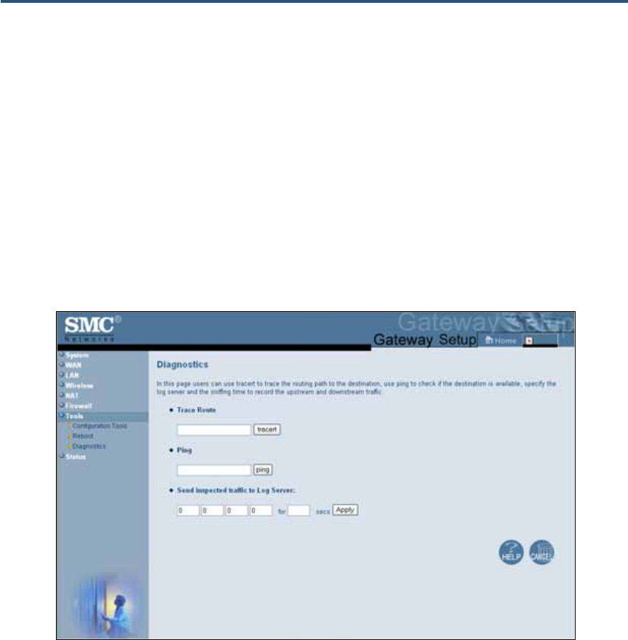
錯誤! 尚未定義樣式。
80
SMC8014WN and SMC8014WN2 Wireless Cable Modem Gateway Administrator Manual
Diagnostics Menu
Path: Tools > Diagnostics
The Diagnostics menu lets you perform three diagnostics to test the Gateway’s connectivity.
y The Trace Route section lets you trace the routing path from the Gateway to the
destination and router. See page 82.
y The Ping section lets you ascertain whether a destination is available. See page 81.
y The Send inspected traffic to Log Server lets you specify the IP address for a log
server, and the sniffing time to record the upstream and downstream traffic. See page 83.
Figure 50. Diagnostics Menu
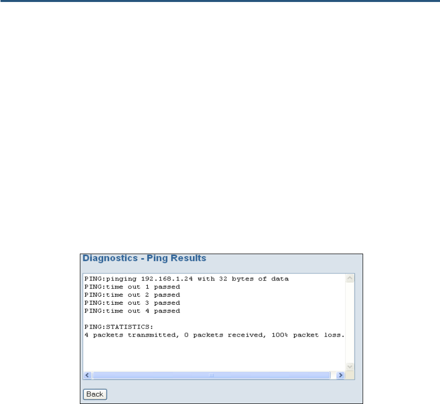
錯誤! 尚未定義樣式。
81
SMC8014WN and SMC8014WN2 Wireless Cable Modem Gateway Administrator Manual
Using the Ping Tool
Using the ping tool, you can check the connectivity between the Gateway and another local
or remote device. The Gateway provides a ping tool for conducting the ping with the default
Gateway, across the RF interface, or across the WAN interface. This tool sends a small
packet of data and then waits for a reply. When you ping a computer IP address and receive
a reply, it confirms that the device is connected to the Gateway.
To perform ping activities, perform the following procedure under Ping on the Diagnostics
menu.
1. In the Ping field, enter the IP address or domain name of a target host.
2. Click the ping button. The results appear in the Diagnostics – Ping Results screen (see
Figure 51). The results screen may flash as the contents refresh during the ping.
3. To close the results screen, click the Back button.
Figure 51. Sample Results for a Ping
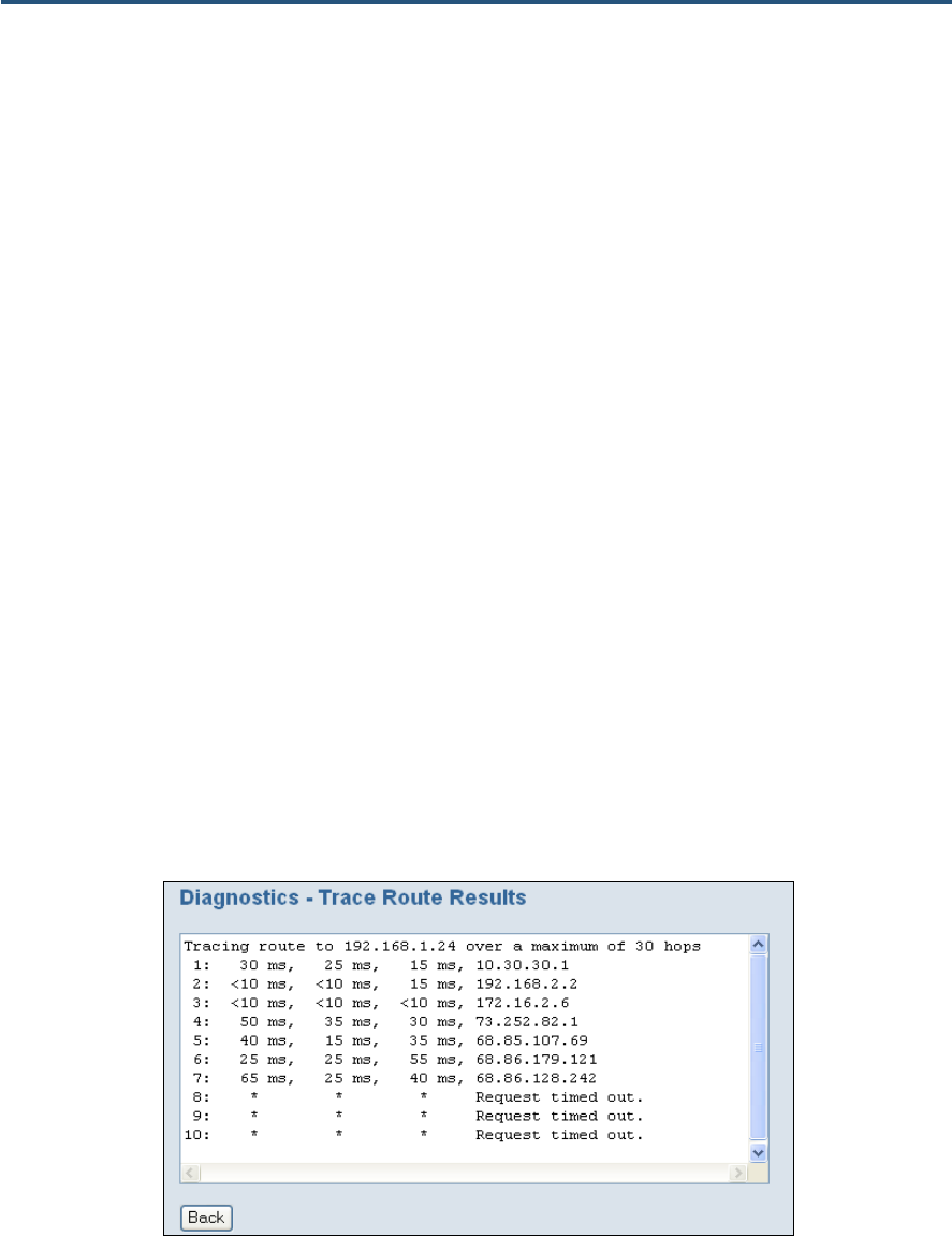
錯誤! 尚未定義樣式。
82
SMC8014WN and SMC8014WN2 Wireless Cable Modem Gateway Administrator Manual
Using the Trace Route Tool
The Gateway provides a trace route tool for conducting the trace route with the default
Gateway, across the RF interface, or across the WAN interface. This tool provides a
supplemental role to the ping tool. While the ping tool confirms IP network reachability, you
cannot pinpoint and improve some isolated problems.
Consider the following situations:
y When there are many hops (for example, gateways or routes) between the Gateway and
the destination, and there is a problem somewhere along the path. The destination
system may have a problem, but you need to know where a packet is actually lost.
y The ping tools do not tell you the reasons for a lost packet.
The trace route tool can tell you where the packet is located and why the route is lost. Using
this tool, you can map a network path in real time from the Gateway to a local or public host.
To perform trace route activities, use the following procedure under Trace Route on the
Diagnostics menu.
1. In the Trace Route field, enter the IP address or domain name of a target host.
2. Click the tracert button. The trace route results appear in the Diagnostics – Trace Route
Results screen, as the Gateway sends UDP packets to each device between the Gateway
and the destination (see Figure 52). It starts with the nearest device and expands the
search by one hop until the destination is reached or the trace route times out. The results
screen may flash as the contents refresh during the trace route operation.
3. To close the screen, click the Back button.
Figure 52. Example of Results for Trace Route
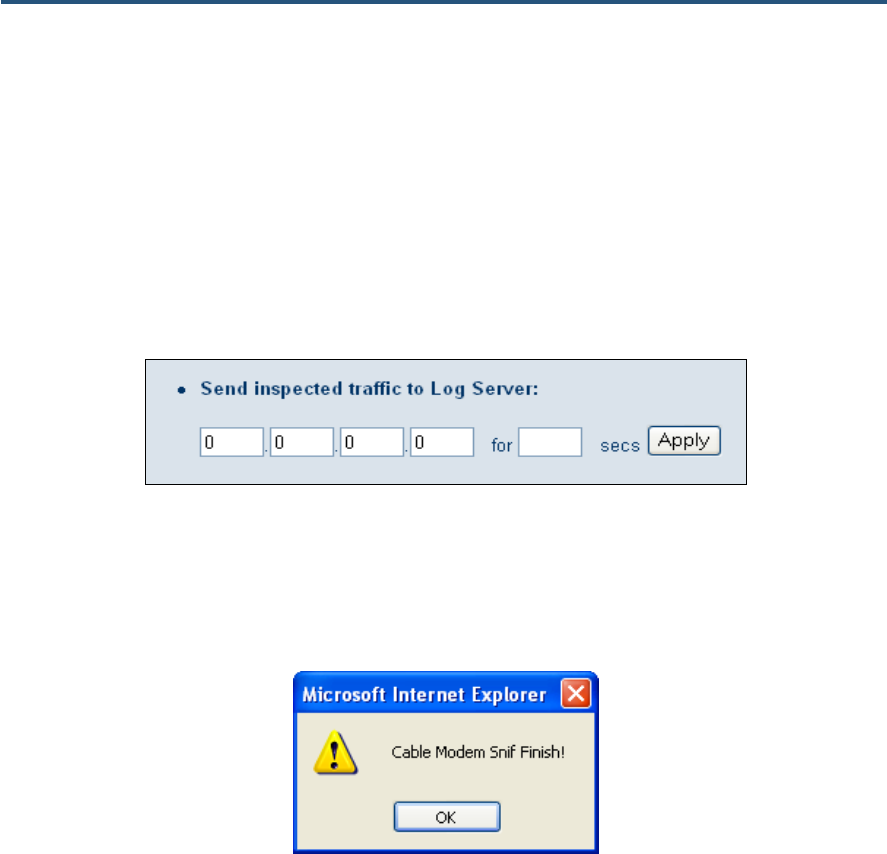
錯誤! 尚未定義樣式。
83
SMC8014WN and SMC8014WN2 Wireless Cable Modem Gateway Administrator Manual
Sending Inspected Traffic to a Log Server
The Gateway can inspect upstream and downstream traffic, and log the results to the syslog
server, where they can be further examined.
To send inspected traffic to a log server, perform the following procedure under Send
inspected traffic to Log Server on the Diagnostics menu.
1. In the first four fields, enter the IP address of the log server.
2. In the for field, enter the number of seconds that inspected traffic is to be sent to the log
server.
3. Click the Apply button. The Gateway sniffs the traffic, logs the traffic to the syslog, and
displays the message in Figure 53 when the number of seconds elapses.
4. Click OK to close the message.
You can now examine the sniffed traffic using appropriate syslog daemons and applications.
Figure 53. Sniffing Complete Message

錯誤! 尚未定義樣式。
84
SMC8014WN and SMC8014WN2 Wireless Cable Modem Gateway Administrator Manual
Status Menu
Path: Status
The Status menu is a read-only page that shows:
y Whether Residential Gateway (RG) functions are enabled.
y Current time and system uptime
y Internet, Gateway, information, wireless, and interface uptime and traffic count data
y Network log. Buttons are provided for clearing, refreshing, and sending the log. To send
the log, email/syslog notifications must be enabled (see page 69); if it isn’t, an error
message appears if you click the Send the Logs button.
y The LAN client log, which shows information about LAN clients connected to the
Gateway. Buttons are provided for refreshing the information shown and releasing IP
addresses.
y Cable modem system event log, with information about the cable modem operation.
Buttons are provided for clearing, refreshing, and sending the log. To send the log,
email/syslog notifications must be enabled (see page 69); if it isn’t, an error message
appears if you click the Send the Logs button.
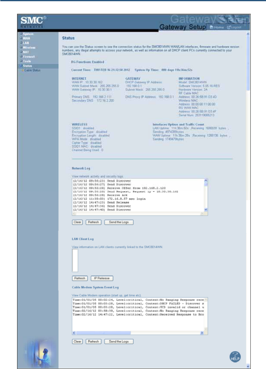
錯誤! 尚未定義樣式。
85
SMC8014WN and SMC8014WN2 Wireless Cable Modem Gateway Administrator Manual
Figure 54. Example of Status Page
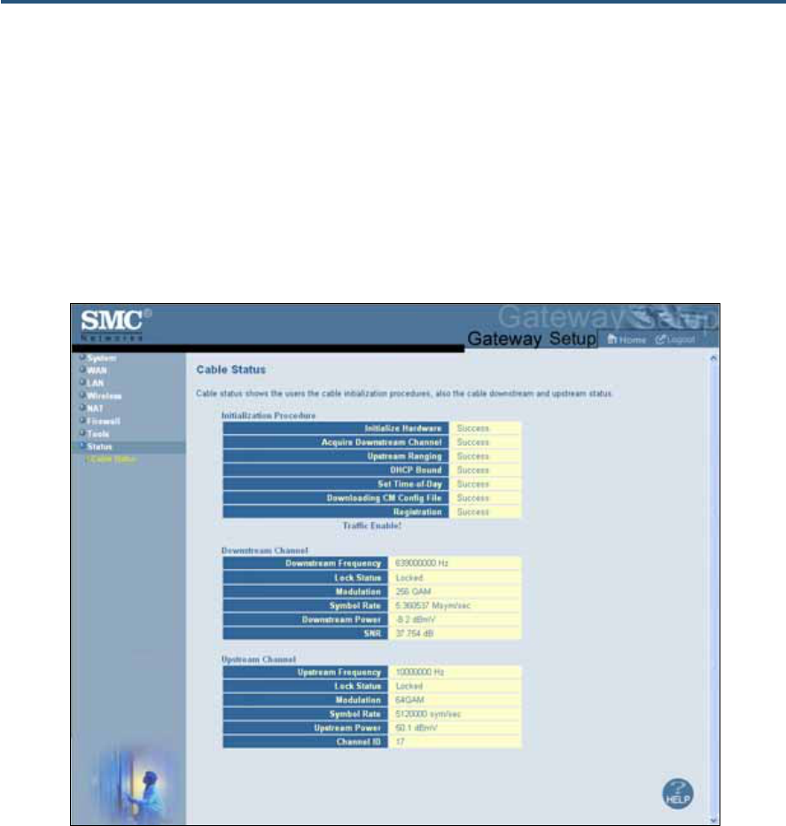
錯誤! 尚未定義樣式。
86
SMC8014WN and SMC8014WN2 Wireless Cable Modem Gateway Administrator Manual
Cable Status Menu
Path: Status > Cable Status
The Cable Status menu is a read-only page that shows the:
y User’s cable initialization procedures
y Cable upstream status
y Cable downstream status
Figure 55. Example of Cable Status Page
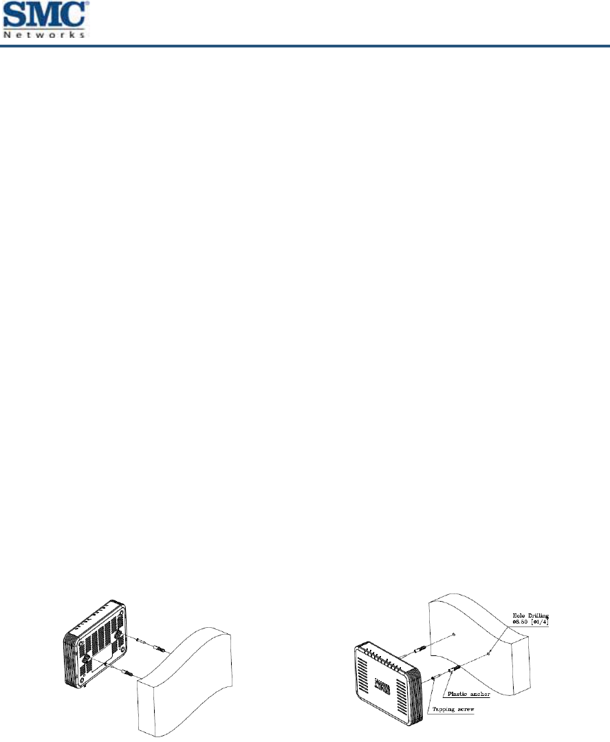
87
SMC8014WN and SMC8014WN2 Wireless Cable Modem Gateway Administrator Manual
Appendix A - Wall Mounting the SMC8014WN
The SMC8014WN Gateway can be wall mounted if desired (the SMC8014WN2 cannot be
wall mounted). To wall mount the SMC8014WN Gateway, perform the following procedure.
1. Locate the devices as specified by the local or national codes governing residential or
business cable TV and communication services.
2. Follow all local standards for installing a network-interface unit/network interface device
(NIU/NID).
3. Be sure the AC power plug is disconnected from all outlets and that all cables are removed
from the back of the Gateway before starting the installation.
4. Decide whether you want to mount the Gateway horizontally or vertically.
5. Use M.35 x 38mm screws with a flat underside and maximum screw head diameter of 9.0
mm to mount the Gateway. See the screw-mounting dimension in the following figures to
mount the Gateway properly. If possible, mount the Gateway on concrete, masonry, a
wooden stud, or other solid wall materials. Use anchors if necessary.
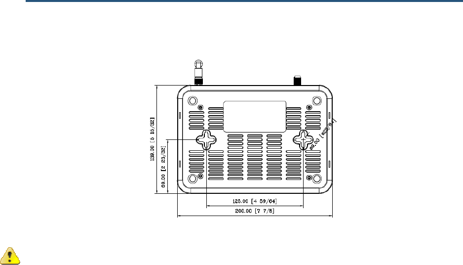
錯誤! 尚未定義樣式。
88
SMC8014WN and SMC8014WN2 Wireless Cable Modem Gateway Administrator Manual
Caution: Before drilling holes, check the structure for potential damage to water, gas, or
electrical lines.
1. Drill the holes to a depth of at least 1 inch (25 mm). There must be 0.5 inches
(10mm) between the wall and the underside of the screw head.
2. After mounting, reconnect the coaxial cable and re-plug the power cord.
3. Route the cables properly to avoid safety hazards.

89
SMC8014WN and SMC8014WN2 Wireless Cable Modem Gateway Administrator Manual
Appendix B - Compliances
FCC Interference Statement
This equipment has been tested and found to comply with the limits for a Class B digital device pursuant to Part
15 of the FCC Rules. These limits are designed to provide reasonable protection against radio interference in a
commercial environment. This equipment can generate, use and radiate radio frequency energy and, if not
installed and used in accordance with the instructions in this manual, may cause harmful interference to radio
communications. Operation of this equipment in a residential area is likely to cause interference, in which case
the user, at his own expense, will be required to take whatever measures are necessary to correct the
interference. If this equipment does cause harmful interference to radio or television reception, which can be
determined by turning the equipment off and on, the user is encouraged to try to correct the interference by one
of the following measures:
y Reorient or relocate the receiving antenna.
y Increase the separation between the equipment and receiver.
y Connect the equipment into an outlet on a circuit different from that to which the receiver is connected.
y Consult the dealer or an experienced radio/TV technician for help.
The device complies with Part 15 of the FCC Rules. Operation is subject to the following two conditions: (1) This
device may not cause harmful interference, and (2) this device must accept any interference received, including
interference that may cause undesired operation.
FCC Caution: Any changes or modifications not expressly approved by the party responsible for compliance
could void the user’s authority to operate this equipment.
IEEE 802.11b or 802.11g operation of this product in the U.S.A is firmware-limited to channels 1 through 11.
IMPORTANT NOTE:
FCC Radiation Exposure Statement:
This equipment complies with FCC radiation exposure limits set forth for an uncontrolled environment. This
equipment should be installed and operated with minimum distance 20cm between the radiator & your body.
This transmitter must not be co-located or operating in conjunction with any other antenna or transmitter.
The availability of some specific channels and/or operational frequency bands are country dependent and are
firmware programmed at the factory to match the intended destination. The firmware setting is not accessible by
the end user.
Note to CATV System Installer - This reminder is provided to call to the CATV systems installer's attention
Section 820-93 of the National Electric Code, which provides guideline for proper grounding and, in particular,
specify that the Coaxial cable shield shall be connected to the grounding system of the building, as close to the
point of cable entry as practical.

90
SMC8014WN and SMC8014WN2 Wireless Cable Modem Gateway Administrator Manual
Index
A
Access control, 58
adding customer-defined filter, 60
adding predefined filter, 59, 60
Access Control menu, 58
Adding
customer-defined filter for access control, 60
customer-defined service for port forwarding, 54
predefined filter for access control, 59, 60
predefined service for port forwarding, 53
Alert options, 71
Alerts, 69
Apple Macintosh TCP/IP configuration, 27
Auto-negotiation, 48
B
Blocking
domain, 67
keyword, 66
C
Computer exempted from URL blocking, 67
Configuration, 28
Configuring
access control, 58
alert options, 71
auto-negotiation, 48
DHCP, 46
duplex mode, 48
email alerts, 70
idle timeout, 37
login password, 37
private LAN IP address, 46
special applications, 62
syslog entries, 71
TCP/IP, 19
Connecting
LAN, 17
WAN, 18
Conventions in this document, vii
Customer UI Setup menu, 41
Customer-defined
service for port forwarding, 54
Customer-defined filter, 60
D
DHCP setting, 46
Diagnostics menu, 80
Disabling
firewall, 30
LAN ports, 48
security software, 30
Disabling proxy settings
Firefox, 30
Internet Explorer, 29
Safari, 30
DMZ (Demilitarized Zone) menu, 72
Document
conventions, vii
organization, vii
Domain blocking, 67
Duplex mode, 48
E
Email alerts, 69, 70
Enabling LAN ports, 48
Ether Switch Port Control menu, 48
Exempted computers, 67

Index
91
SMC8014WN and SMC8014WN2 Wireless Cable Modem Gateway Administrator Manual
F
Factory defaults
restoring, 15
Firefox, disabling proxy settings, 30
Firewall
disabling, 30
Front panel, 11, 13
LEDs, 11, 12, 14
G
Gateway
configuring, 28
connecting to the LAN, 17
connecting to the WAN, 18
front panel, 11, 13
installing, 16
key features, vi
LEDs, 11, 12, 14
locating, 17
package contents, 10
powering on, 18
preconfiguring, 29
rear panel, 12, 14
rebooting and losing custom settings, 15, 77
system requirements, 10
Web management, 31
I
Installation, 16
Internet Explorer, disabling proxy settings, 29
K
Key features, vi
Keyword blocking, 66
L
LAN connection, 17
LAN ports, enabling or disabling, 48
LAN Settings menu, 46
Lease time, 46
LEDs, 11, 12, 14
Locating the Gateway, 17
Logging in to Web management, 31
M
MAC Spoofing menu, 45
Menus
Access Control, 58
Customer UI Setup, 41
Diagnostics, 80
DMZ (Demilitarized Zone), 72
Ether Switch Port Control, 48
LAN Settings, 46
MAC Spoofing, 45
NAT Settings, 52
Password Settings, 37
Reboot, 77
Remote Management, 39
Schedule Rules, 68
Security Settings (Firewall), 57
System Settings, 35
Trigger, 63
URL Blocking, 65
WAN Settings, 43
Microsoft
TCP/IP configuration for Windows 2000, 20
TCP/IP configuration for Windows 7, 24
TCP/IP configuration for Windows Vista, 22
TCP/IP configuration for Windows XP, 21
N
NAT Settings menu, 52
P
Package contents, 10
Password Settings menu, 37
Ping, 80
Port forwarding
adding customer-defined service, 54
adding predefined service, 53
Port triggering, 63

Index
92
SMC8014WN and SMC8014WN2 Wireless Cable Modem Gateway Administrator Manual
Powering-on the Gateway, 18
Preconfiguration guidelines, 29
Predefined
service for adding port forwarding, 53
Predefined filter, 59, 60
Private LAN IP settings
DHCP, 46
domain name, 46
IP address, 46
IP subnet mask, 46
lease time, 46
Proxy settings, 29
R
RADIUS configuration, 37
Rear panel, 12, 14
Reboot menu, 77
Rebooting
losing custom settings, 15, 77
Remote Management menu, 39
Requirements, 10
Restoring factory defaults, 15
S
Safari, disabling proxy settings, 30
Schedule Rules menu, 68
Screens in Web management, 32
Security Settings (Firewall) menu, 57
Security software, 30
Spoofing MAC addresses, 45
Syslog
alerts, 69
entries, 71
System requirements, 10
System Settings menu, 35
T
TACACS configuration, 37
TACACS+ configuration, 37
TCP/IP configuration, 19
Apple Macintosh, 27
Microsoft Windows 2000, 20
Microsoft Windows 7, 24
Microsoft Windows Vista, 22
Microsoft Windows XP, 21
Trace route, 80
Trigger menu, 63
Triggering ports, 63
U
URL Blocking menu, 65
W
Wall mounting the SMC8014WN, 87
WAN connection, 18
WAN ping, 80
WAN Settings menu, 43
WAN trace route, 80
Web management
Access Control menu, 58
Customer UI Setup menu, 41
Diagnostics menu, 80
DMZ (Demilitarized Zone) menu, 72
Ether Switch Port Control menu, 48
LAN Settings menu, 46
logging in, 31
MAC Spoofing menu, 45
NAT Settings menu, 52
Password Settings menu, 37
Reboot menu, 77
Remote Management menu, 39
Schedule Rules menu, 68
screens, 32
Security Settings (Firewall) menu, 57
System Settings menu, 35
Trigger menu, 63
URL Blocking menu, 65
WAN Settings menu, 43

20 Mason
Irvine, CA. 92618
U.S.A.
http://www.smc.com
Document number: 50516RES02212012