SMC Networks D3GN301 DOCSIS 3.0 Wireless Cable Modem Gateway User Manual
SMC Networks Inc DOCSIS 3.0 Wireless Cable Modem Gateway
User Manual

SMCD3GN3 Administrator
User Manual
DOCSIS 3.0 Wireless Cable Modem Gatewa
y
FastFind Links
Getting to Know the Gateway
Installing the Gateway
Configuring Your Computer for TCP/IP
Configuring the Gateway
SMC Networks
20 Mason
Irvine, CA. 92618
U.S.A.
Copyright © 2011 SMC Networks
All Rights Reserved
Information furnished by SMC Networks, Inc. (SMC) is believed to be accurate and reliable. However,
no responsibility is assumed by SMC for its use, or for any infringements of patents or other rights of
third parties which may result from its use. No license is granted by implication or otherwise under
any patent or patent rights of SMC. SMC reserves the right to change specifications at any time
without notice
No part of this publication may be reproduced or transmitted in any form or by any means, electronic
or mechanical, including photocopying and recording, or stored in a database or retrieval system for
any purpose without the express written permission of SMC.
Microsoft and Windows are registered trademarks of Microsoft Corporation. Apple and Macintosh are
registered trademarks of Apple, Inc. All other brands, product names, trademarks, or service marks
are property of their respective owners.
This product (Model :SMCD3GN3) includes software code developed by third parties, including
software code subject to the GNU General Public License (“GPL”) or GNU Lesser General Public
License (LGPL”). As applicable, the terms of the GPL and LGPL, and information on obtaining access
to the GPL code and LGPL used in this product, are available to you at http://gpl.smc.com/. The GPL
code and LGPL code used in this product is distributed WITHOUT ANY WARRANTY and is subject to
the copyrights of one or more authors. For details, see the GPL Code and LGPL Code for this product
and the terms of the GPL and LGPL.
SMCD3GN3 Wireless Cable Modem Gateway Administrator Manual

iii
SMCD3GN2 Wireless Cable Modem Gateway Administrator Manual
Contents
Preface..................................................................................................................... vi
Key Features..............................................................................................................vii
Document Organization.............................................................................................viii
Document Conventions.............................................................................................viii
Safety and Warnings ...........................................................................................viii
Typographic Conventions........................................................................................... ix
1 Getting to Know the Gateway............................................................................ 10
Unpacking Package Contents...................................................................................11
System Requirements...............................................................................................11
Front Panel................................................................................................................12
Configuring Wireless Security ...................................................................................14
Rear Panel ................................................................................................................14
Restoring Factory Defaults........................................................................................15
2 Installing the Gateway........................................................................................ 16
Finding a Suitable Location.......................................................................................17
Connecting to the LAN ..............................................................................................17
Connecting the WAN.................................................................................................18
Powering on the Gateway .........................................................................................18
3 Configuring Your Computer for TCP/IP............................................................ 19
Configuring Microsoft Windows 2000........................................................................20
Configuring Microsoft Windows XP...........................................................................21
Configuring Microsoft Windows Vista........................................................................22
Configuring Microsoft Windows 7..............................................................................24
Configuring an Apple® Macintosh® Computer ...........................................................26
4 Configuring the Gateway ................................................................................... 28
Pre-configuration Guidelines.....................................................................................29
Disabling Proxy Settings......................................................................................29
Disabling Proxy Settings in Internet Explorer ................................................29
Disabling Proxy Settings in Firefox................................................................29
Disabling Proxy Settings in Safari .................................................................30
Disabling Firewall and Security Software ............................................................30
Accessing the Gateway’s Web Management............................................................31
Understanding the Web Management Interface Screens .........................................32

Contents
iv
SMCD3GN2 Wireless Cable Modem Gateway Administrator Manual
Web Management Interface Menus and Submenus .................................................33
System Settings Menu.........................................................................................36
Password Settings Menu.....................................................................................38
Remote Management Menu................................................................................43
Customer UI Setup Menu....................................................................................44
WAN Settings Menu ............................................................................................46
MAC Spoofing Menu ...........................................................................................49
LAN Settings Menu..............................................................................................50
Ether Switch Port Control Menu ..........................................................................53
LAN Access Control Menu ..................................................................................54
Controlling LAN Access.................................................................................56
Adding and Deleting Trusted Client Stations.................................................56
Adding and Deleting Untrusted Client Stations .............................................57
Additional Public Lan Menu.................................................................................58
Adding Public Subnets ..................................................................................59
Public IP Access Control Menu ...........................................................................60
QoS Settings Menu .............................................................................................62
Port Based QoS Menu...................................................................................64
CoS Settings Menu........................................................................................65
DSCP Based QoS Menu ...............................................................................67
Queue Settings Menu....................................................................................69
DSCP Remarking Menu ................................................................................71
Routing Menus ....................................................................................................73
Static Routes Menu .......................................................................................73
RIP Control Menu ..........................................................................................75
OSPF Control Menu ......................................................................................79
Adding OSPF Areas to the Cable Interface...................................................81
Wireless Basic Settings Menu.............................................................................83
Wireless Encryption Settings Menu.....................................................................85
WPS Setup..........................................................................................................88
MAC Filtering.......................................................................................................91
Adding and Deleting Wireless Client Stations ...............................................92
Advanced Wireless Settings Menu......................................................................93
NAT Settings .......................................................................................................95
Port Forwarding Menu.........................................................................................96
Adding Predefined Services ..........................................................................97
Adding Customer-Defined Services ..............................................................99
1-to-1 Mapping Menu ........................................................................................102
Security Settings (Firewall) Menu......................................................................105
Enabling or Disabling Firewall .....................................................................105
Configuring Access Control.........................................................................107
Configuring Special Applications.................................................................119

Contents
v
SMCD3GN2 Wireless Cable Modem Gateway Administrator Manual
Configuring URL Blocking ...........................................................................122
Configuring Schedule Rules........................................................................124
Configuring Email and Syslog Alerts ...........................................................125
Configuring DMZ Settings ...........................................................................129
Using the Configuration Tools Menu .................................................................130
Switching Working Scripts...........................................................................132
Backing Up the Gateway’s Current Configuration Locally...........................132
Restoring the Gateway’s Current Configuration Locally..............................133
Backing Up the Gateway’s Current Configuration Remotely.......................134
Restoring the Gateway’s Current Configuration Remotely..........................135
Restoring Factory Defaults ..........................................................................136
Using the Reboot Menu to Reboot the Gateway...............................................137
Using the Diagnostics Menu..............................................................................138
Using the Ping Tool .....................................................................................139
Using the Trace Route Tool.........................................................................141
Sending Inspected Traffic to a Log Server ..................................................143
Using the SNTP Menu.......................................................................................144
Configuring VPN Settings..................................................................................145
Using the VPN Menu ...................................................................................145
Using the Access Control Menu to Allow CPEs to Access IPSec VPN
Tunnel ............................................................................................147
Using the VPN – Tunnel Configuration Menu..............................................148
Using the VPN – PPTP / L2TP User Configuration Menu ...........................153
Viewing Status Information................................................................................156
Viewing Cable Status Information .....................................................................158
Appendix A - Compliances ................................................................................. 160
Index ..................................................................................................................... 161
vi
SMCD3GN2 Wireless Cable Modem Gateway Administrator Manual
Preface
Congratulations on your purchase of the SMCD3GN3 Wireless Cable Modem Gateway. The
SMCD3GN3 Wireless Cable Modem Gateway is the ideal all-in-one wired and wireless
solution for the home or business environment. SMC is proud to provide you with a powerful,
yet simple communication device for connecting your local area network (LAN) to the
Internet.
This user manual contains all the information administrators need to install and configure
your new SMCD3GN3 Wireless Cable Modem Gateway.

Preface
vii
SMCD3GN2 Wireless Cable Modem Gateway Administrator Manual
Key Features
The following list summarizes the Gateway’s key features.
y Integrated, CableLabs-compliant DOCSIS 1.1/ 2.0 /3.0 cable modem
y Four 10/100/1000 Mbps Auto-Sensing LAN ports with Auto-MDI/MDIX
y High-speed 300 Mbps IEEE 802.11n Wireless Access Point
y Dynamic Host Configuration Protocol (DHCP) for dynamic IP configuration, and Domain
Name System (DNS) for domain name mapping
y One USB 2.0 port
y IEEE 802.11 b/g/n interoperability with multiple vendors
y Wireless WEP, WPA, and WPA2 encryption, Hide SSID, and MAC Filtering
y VPN pass-through support using PPTP, L2TP, or IPSec
y Advanced SPI firewall Gateway for enhanced network security from attacks over the
Internet:
– Firewall protection with Stateful Packet Inspection
– Client privileges
– Hacker prevention
– Protection from denial of service (DoS) attacks
– Network Address Translation (NAT)
y Universal Plug and Play (UPnP) enables seamless configuration of attached devices
y Quality of Service (QoS) ensures high-quality performance with existing networks
y Effortless plug-and-play installation
y Intuitive graphical user interface (GUI) configuration, regardless of operating system
y Comprehensive front panel LEDs for network status and troubleshooting
y Compatible with all popular Internet applications
Preface
viii
SMCD3GN2 Wireless Cable Modem Gateway Administrator Manual
Document Organization
This document consists of four chapters and two appendixes.
y Chapter 1 - describes the contents in the Gateway package, system requirements, and
an overview of the Gateway’s front and rear panels.
y Chapter 2 - describes how to install the Gateway.
y Chapter 3 - describes how to configure TCP/IP settings on the computer you will use to
configure the Gateway.
y Chapter 4 - describes how to configure the Gateway.
y Appendix A - contains compliance information.
Document Conventions
This document uses the following conventions to draw your attention to certain information.
Safety and Warnings
This document uses the following symbols to draw your attention to certain information.
Symbol Meaning Description
Note Notes emphasize or supplement important points of the main text.
Tip Tips provide helpful information, guidelines, or suggestions for performing tasks more
effectively.
Warning Warnings indicate that failure to take a specified action could result in damage to the
device.
Electric Shock Hazard This symbol warns users of electric shock hazard. Failure to take appropriate
precautions such as not opening or touching hazardous areas of the equipment could
result in injury or death.
Preface
ix
SMCD3GN2 Wireless Cable Modem Gateway Administrator Manual
Typographic Conventions
This document also uses the following typographic conventions.
Convention Description
Bold Indicates text on a window, other than the window title, including menus, menu options, buttons, fields, and labels.
Italic Indicates a variable, which is a placeholder for actual text provided by the user or system. Angled brackets (< >)
are also used to indicate variables.
screen/code Indicates text that is displayed on screen or entered by the user.
< > angled
brackets Indicates a variable, which is a placeholder for actual text provided by the user or system. Italic font is also used to
indicate variables.
[ ] square
brackets Indicates optional values.
{ } braces Indicates required or expected values.
| vertical bar Indicates that you have a choice between two or more options or arguments.

10
SMCD3GN2 Wireless Cable Modem Gateway Administrator Manual
1 Getting to Know the Gateway
Before you install the SMCD3GN3 Wireless Cable Modem Gateway, check the package
contents and become familiar with the Gateway’s front and back panels.
The topics covered in this chapter are:
y Unpacking Package Contents (page 11)
y System Requirements (page 11)
y Front Panel (page 12)
y Configuring Wireless Security (page 14)
y Rear Panel (page 14)
y Restoring Factory Defaults (page 15)

錯誤! 尚未定義樣式。
11
SMCD3GN2 Wireless Cable Modem Gateway Administrator Manual
Unpacking Package Contents
The SMCD3GN3 package should include the following items:
y One SMCD3GN3 Wireless Cable Modem Gateway
y One power cord
y One Category 5E Ethernet cable
y One CD that contains this User Manual
System Requirements
To complete the installation, you will need the following items:
y Provisioned Internet access on a cable network that supports cable modem service
y A computer with a wired network adapter with TCP/IP installed
y A Java-enabled Web browser, such as Microsoft Internet Explorer 5.5 or above
y Microsoft® Windows® 2000 or higher for USB driver support
錯誤! 尚未定義樣式。
12
SMCD3GN2 Wireless Cable Modem Gateway Administrator Manual
Front Panel
The front panel of the SMCD3GN3 Wireless Cable Modem Gateway contains a set of light-
emitting diode (LED) indicators. These LEDs show the status of the Gateway and simplify
troubleshooting. The front panel also contains a WPS button for configuring wireless security
automatically.
Figure 1 shows the front panel of the SMCD3GN3 Wireless Cable Modem Gateway. Table 1
describes the front panel LEDs.
Figure 1. Front Panel of the SMCD3GN3 Wireless Cable Modem Gateway
錯誤! 尚未定義樣式。
13
SMCD3GN2 Wireless Cable Modem Gateway Administrator Manual
Table 1. Front Panel LEDs
LED Color Description
POWER Green ON = power is supplied to the Gateway.
OFF = power is not supplied to the Gateway.
Green Blinking = scanning for DS channel.
ON = synchronized on 1 channel only.
DS
Blue ON = synchronized with more than 1 channel (DS Bond mode).
DS and US Both DS and US blinking together = operator is performing maintenance.
Green Blinking = ranging is in progress.
ON = ranging is complete on 1 channel only.
OFF = scanning for DS channel.
US
Blue ON = ranging is complete, operate with more than 1 channel (US Bond mode).
ONLINE Green Blinking =.cable interface is acquiring IP, ToD, CM configuration.
ON = Gateway is operational.
OFF = Gateway is offline.
Green Blinking = data is transmitting.
ON = connected at 10 or 100 Mbps.
OFF = no Ethernet link detected.
ETH 1 – ETH 4
Blue Blinking = data is transmitting.
ON = connected at 1 Gbps.
OFF = no Ethernet link detected.
WIFI Green Blinking = data is transmitting.
ON = Wi-Fi is enabled.
OFF = Wi-Fi is disabled.
USB Green Reserved for future use.
錯誤! 尚未定義樣式。
14
SMCD3GN2 Wireless Cable Modem Gateway Administrator Manual
⊇
Configuring Wireless Security
The front panel has a WPS button for configuring wireless security automatically. Pressing
this button for 5 seconds automatically configures wireless security. If the client device
supports WPS Push Button Configuration (PBC), press the button on the client within 60
seconds to automatically configure security on the client.
After pressing this button for 5 seconds, the WPS LED on the front panel flashes. When a
client joins the network successfully, the LED remains ON until the next WPS action or the
device reboots. If no client joins, the LED stops blinking after 4 minutes.
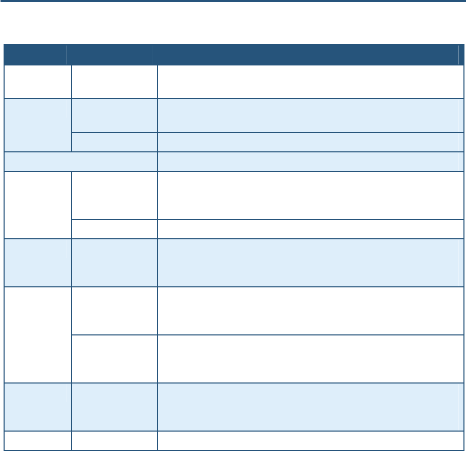
Rear Panel
The rear panel of the SMCD3GN3 Wireless Cable Modem Gateway contains a reset button
and the ports for attaching the supplied power adapter and making additional connections.
Figure 2 shows the rear panel components and Table 2 describes their meanings.
Figure 2. Rear View of the SMCD3GN3 Wireless Cable Modem Gateway
Table 2. SMCD3GN3 Wireless Cable Modem Gateway Rear Panel Components
Item Description
⊇ USB USB 2.0 high-speed port for storing configurations externally.
⊄ ETH 1 - 4 Four 10/100/1000 auto-sensing RJ-45 switch ports. Connect devices on your local area network
such as a computer, hub, or switch to these ports.
⊂ Reset button Use this button to reset the power or restore the default factory settings (see “Restoring Factory
Defaults,” below). This button is recessed to prevent accidental resets of the Gateway.
⊆ Cable Connect your coaxial cable line to this port.
∈ Power Connect the supplied power cord to this port.
⊂⊆
∈
⊄

錯誤! 尚未定義樣式。
15
SMCD3GN2 Wireless Cable Modem Gateway Administrator Manual
Restoring Factory Defaults
The Reset button on the back panel can be used to return the Gateway to its factory default
settings. As a result, any changes made to the Gateway’s default settings will be lost.
If you do not have physical access to the Gateway, you can use the GUI to either power
cycle the Gateway (see “Using the Reboot Menu to Reboot the Gateway” on page 137) or
return the Gateway to its factory default settings (see “Restoring Factory Defaults” on page
136).
The following procedure describes how to use the Reset button to power cycle the Gateway
and return it to its original factory default settings.
1. Leave power plugged into the Gateway.
2. Find the Reset button on the back panel, then press and hold it for at least 10 seconds.
3. Release the Reset button.

16
SMCD3GN2 Wireless Cable Modem Gateway Administrator Manual
2 Installing the Gateway
This chapter describes how to install the SMCD3GN3 Wireless Cable Modem Gateway. The
topics covered in this chapter are:
y Finding a Suitable Location (page 17)
y Connecting to the LAN (page 17)
y Connecting the WAN (page 18)
y Powering on the Gateway (page 18)

錯誤! 尚未定義樣式。
17
SMCD3GN2 Wireless Cable Modem Gateway Administrator Manual
Finding a Suitable Location
The SMCD3GN3 Wireless Cable Modem Gateway can be installed in any location with
access to the cable network. All of the cables connect to the rear panel of the Gateway for
better organization and utility. The LED indicators on the front panel are easily visible to
provide users with information about network activity and status.
For optimum performance, the location you choose should:
y Be close to a working AC power outlet
y Allow sufficient air flow around the Gateway to keep the device as cool as possible
y Not expose the Gateway to a dusty or wet environment
y Be an elevated location such as a high shelf, keeping the number of walls and ceilings
between the Gateway and your other devices to a minimum
y Be away from electrical devices that are potential sources of interference, such as ceiling
fans, home security systems, microwaves, or the base for a cordless phone
y Be away from any large metal surfaces, such as a solid metal door or aluminum studs.
Large expanses of other materials such as glass, insulated walls, fish tanks, mirrors,
brick, and concrete can also affect your wireless signal
Connecting to the LAN
Using an Ethernet LAN cable, you can connect the Gateway to a desktop computer,
notebook, hub, or switch. The SMCD3GN3 Wireless supports auto-MDI/MDIX, so you can
use either a standard straight-through or crossover Ethernet cable.
1. Connect either end of an Ethernet cable to one of the four ETH ports on the rear panel of
the Gateway (see Figure 3).
Figure 3. Connecting to an ETH Port on the Gateway Rear Panel
錯誤! 尚未定義樣式。
18
SMCD3GN2 Wireless Cable Modem Gateway Administrator Manual
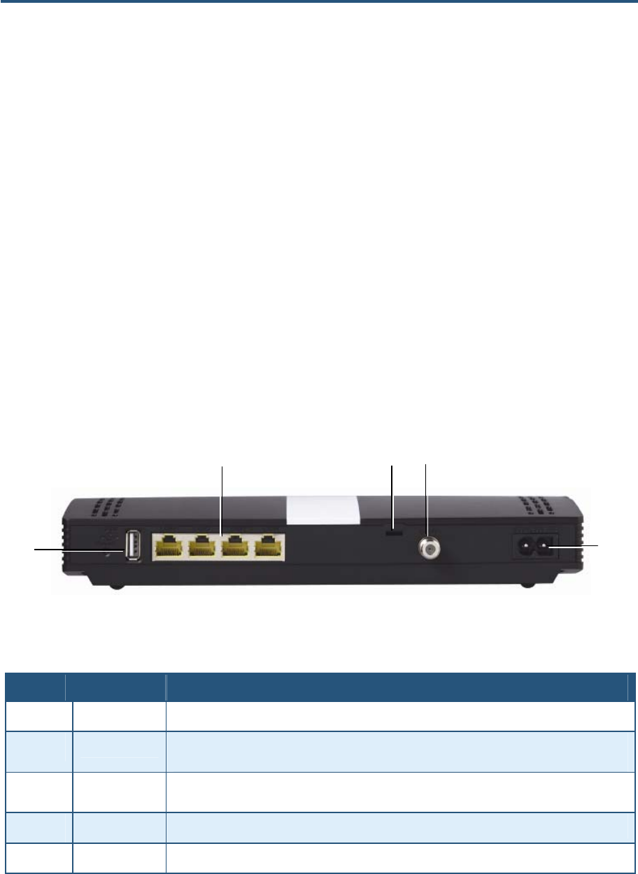
2. Connect the other end of the cable to your computer’s network-interface card (NIC) or to
another network device (see Figure 4).
Figure 4. Connecting the Gateway to the a Laptop or Desktop Computer
Connecting the WAN
To connect the Gateway to a Wide Area Network (WAN) interface:
3. Connect a coaxial cable to the port labeled Cable on the rear panel of the Gateway from a
cable port in your home or office (see Figure 2 on page 14). Use only manufactured coaxial
patch cables with F-type connectors at both ends for all connections.
4. Hand-tighten the connectors to secure the connection.
Powering on the Gateway
After making your LAN and WAN connections, use the following procedure to power on the
Gateway:
1. Connect the supplied power cord to the port on the rear panel of the Gateway (see Figure
2 on page 14).
2. Connect the other end of the power cord to a working power outlet. The Gateway powers
on automatically, the POWER LED on the front panel goes ON, and the other front panel
LEDs show the Gateway’s status (see Table 1 on page 13).
WARNING: Only use the power cord supplied with the Gateway. Using a different
power cord can damage the Gateway and void the warranty.

19
SMCD3GN2 Wireless Cable Modem Gateway Administrator Manual
3 Configuring Your Computer for TCP/IP
After you install the SMCD3GN3 Wireless Cable Modem Gateway, configure the TCP/IP
settings on a computer that will be used to configure the Gateway. This chapter describes
how to configure TCP/IP for various Microsoft Windows and Apple Macintosh operating
systems.
The topics covered in this chapter are:
y Configuring Microsoft Windows 2000 (page 20)
y Configuring Microsoft Windows XP (page 21)
y Configuring Microsoft Windows Vista (page 22)
y Configuring Microsoft Windows 7 (page 24)
y Configuring an Apple® Macintosh® Computer (page 26)
錯誤! 尚未定義樣式。
20
SMCD3GN2 Wireless Cable Modem Gateway Administrator Manual
Configuring Microsoft Windows 2000
Use the following procedure to configure your computer if your computer has Microsoft
Windows 2000 installed.
1. On the Windows taskbar, click Start, point to Settings, and then click Control Panel.
2. In the Control Panel window, double-click the Network and Dial-up Connections icon. If
the Ethernet adapter in your computer is installed correctly, the Local Area Connection
icon appears.
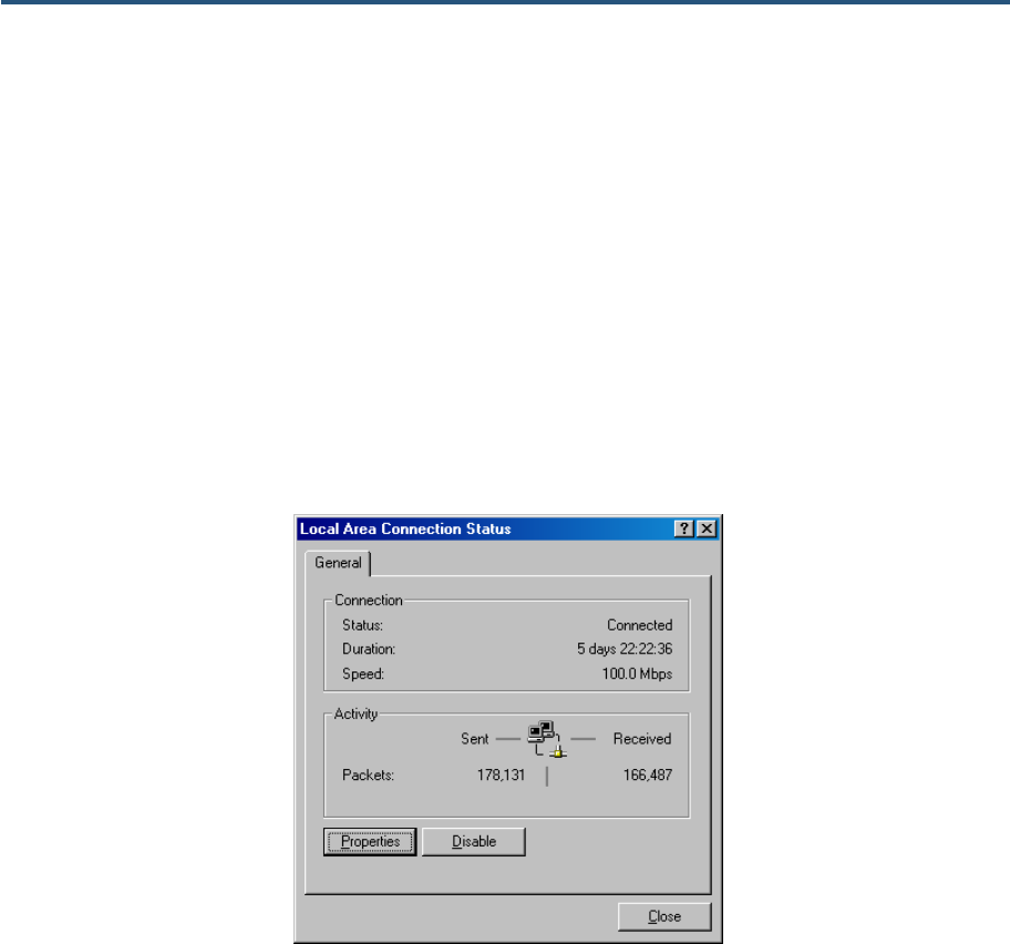
3. Double-click the Local Area Connection icon for the Ethernet adapter connected to the
Gateway. The Local Area Connection Status dialog box appears (see Figure 5).
Figure 5. Local Area Connection Status Window
4. In the Local Area Connection Status dialog box, click the Properties button. The Local
Area Connection Properties dialog box appears.
5. In the Local Area Connection Properties dialog box, verify that Internet Protocol (TCP/IP)
is checked. Then select Internet Protocol (TCP/IP) and click the Properties button.
6. Click Obtain an IP address automatically to configure your computer for DHCP.
7. Click the OK button to save this change and close the Local Area Connection Properties
dialog box.
8. Click OK button again to save these new changes.
9. Restart your computer.
錯誤! 尚未定義樣式。
21
SMCD3GN2 Wireless Cable Modem Gateway Administrator Manual
Configuring Microsoft Windows XP
Use the following procedure to configure a computer running Microsoft Windows XP with the
default interface. If you use the Classic interface, where the icons and menus resemble
previous Windows versions, perform the procedure under “Configuring Microsoft Windows
2000” on page 20.
1. On the Windows taskbar, click Start, click Control Panel, and then click Network and
Internet Connections.
2. Click the Network Connections icon.
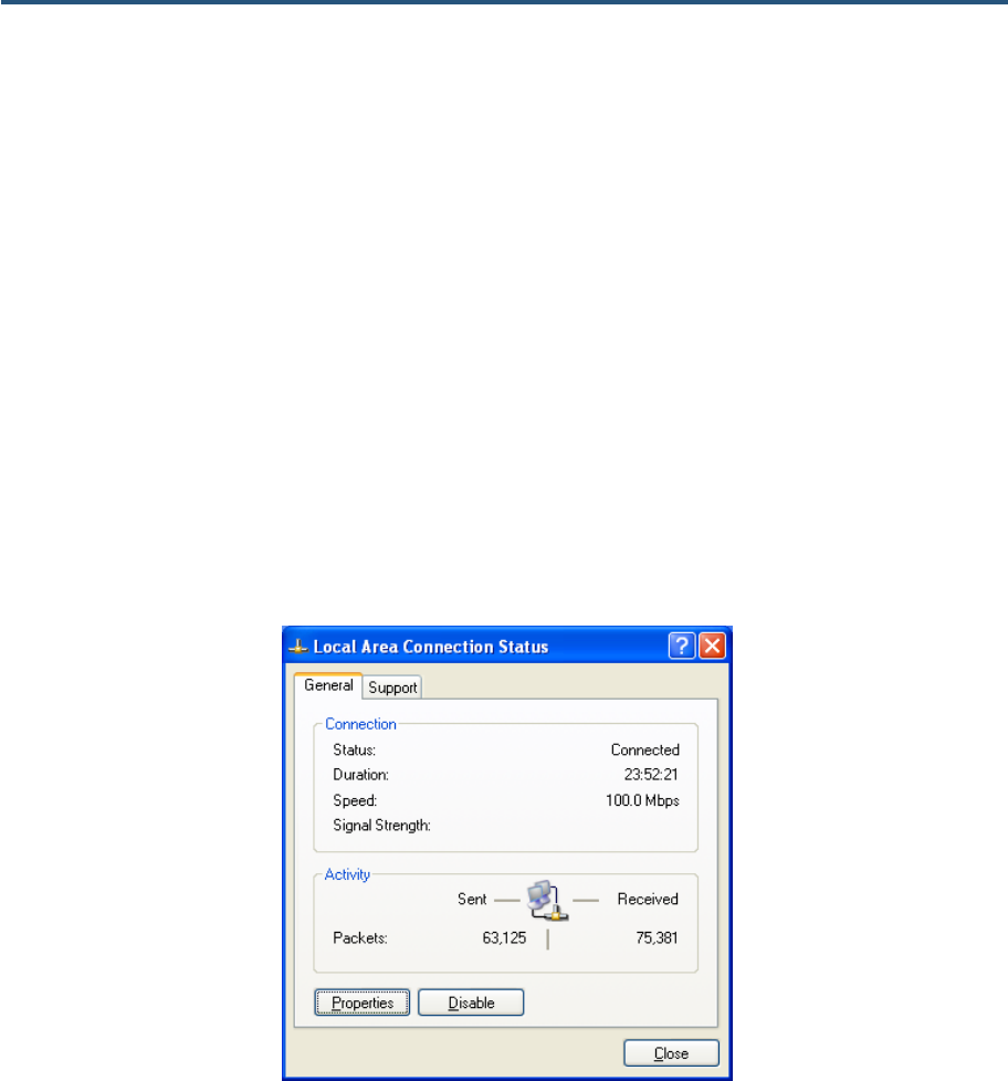
3. Click Local Area Connection for the Ethernet adapter connected to the Gateway. The
Local Area Connection Status dialog box appears.
4. In the Local Area Connection Status dialog box, click the Properties button (see Figure 6).
The Local Area Connection Properties dialog box appears.
Figure 6. Local Area Connection Status Window
5. In the Local Area Connection Properties dialog box, verify that Internet Protocol (TCP/IP)
is checked. Then select Internet Protocol (TCP/IP) and click the Properties button. The
Internet Protocol (TCP/IP) Properties dialog box appears.
6. In the Internet Protocol (TCP/IP) Properties dialog box, click Obtain an IP address
automatically to configure your computer for DHCP. Click the OK button to save this
change and close the Internet Protocol (TCP/IP) Properties dialog box.
7. Click the OK button again to save your changes.
8. Restart your computer.
錯誤! 尚未定義樣式。
22
SMCD3GN2 Wireless Cable Modem Gateway Administrator Manual
Configuring Microsoft Windows Vista
Use the following procedure to configure a computer running Microsoft Windows Vista with
the default interface. If you use the Classic interface, where the icons and menus resemble
previous Windows versions, perform the procedure under “Configuring Microsoft Windows
2000” on page 20.
1. On the Windows taskbar, click Start, click Control Panel, and then select the Network
and Internet icon.
2. Click View Networks Status and tasks and then click Management Networks
Connections.
3. Right-click the Local Area Connection icon and click Properties.
4. Click Continue. The Local Area Connection Properties dialog box appears.
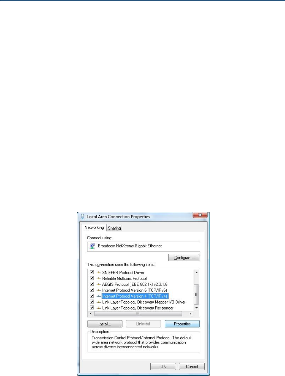
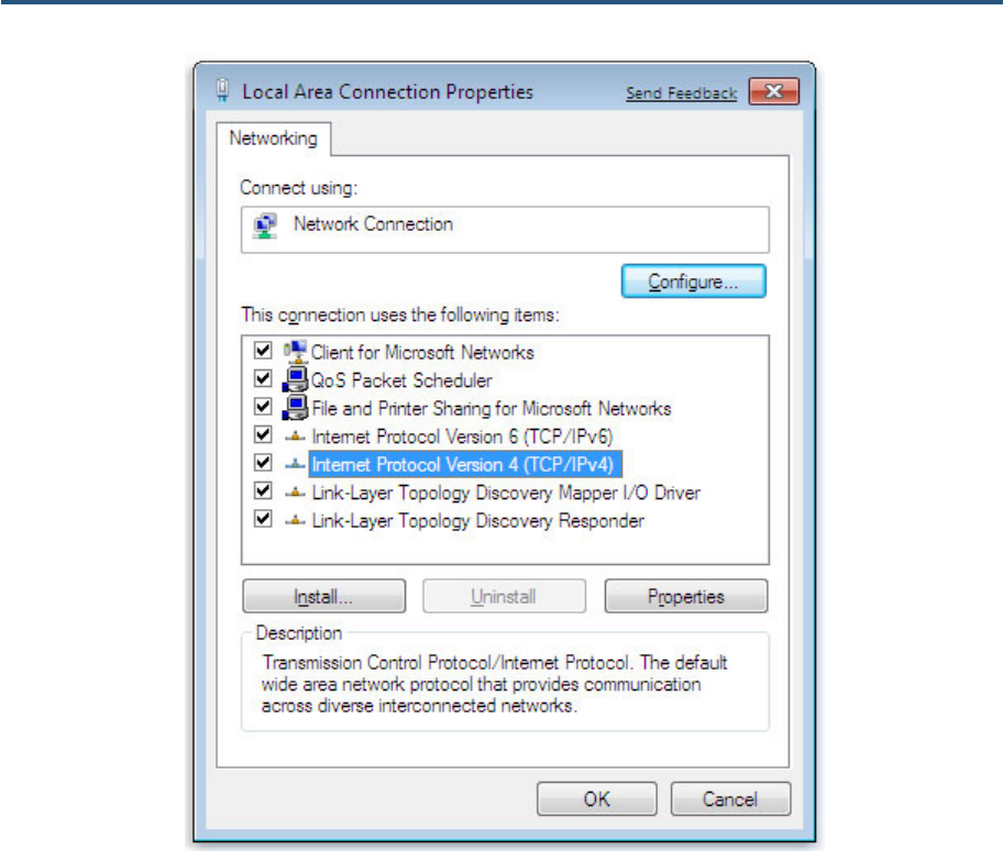
5. In the Local Area Connection Properties dialog box, verify that Internet Protocol
(TCP/IPv4) is checked. Then select Internet Protocol (TCP/IPv4) and click the
Properties button (see Figure 7). The Internet Protocol Version 4 Properties dialog box
appears.
Figure 7. Local Area Connection Properties Window
錯誤! 尚未定義樣式。
23
SMCD3GN2 Wireless Cable Modem Gateway Administrator Manual
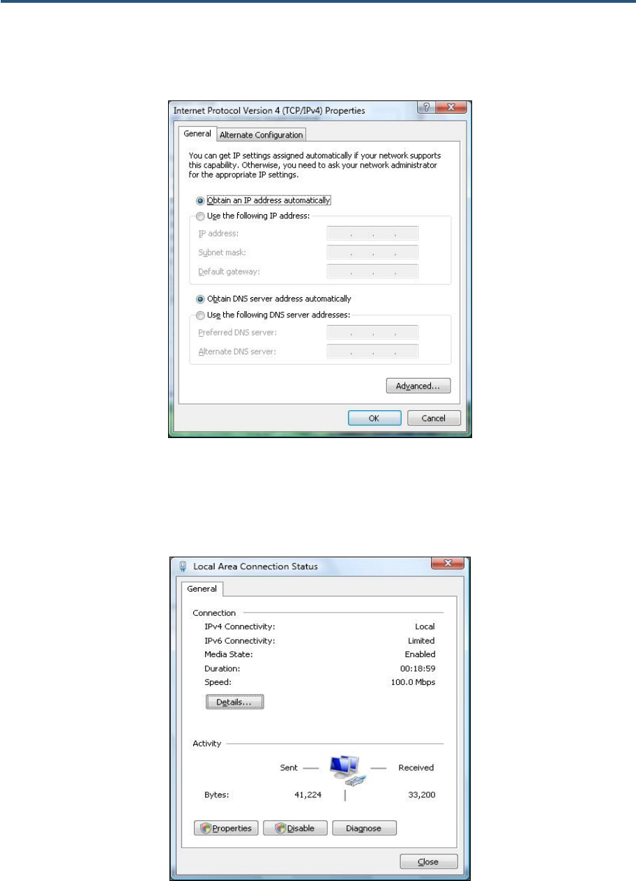
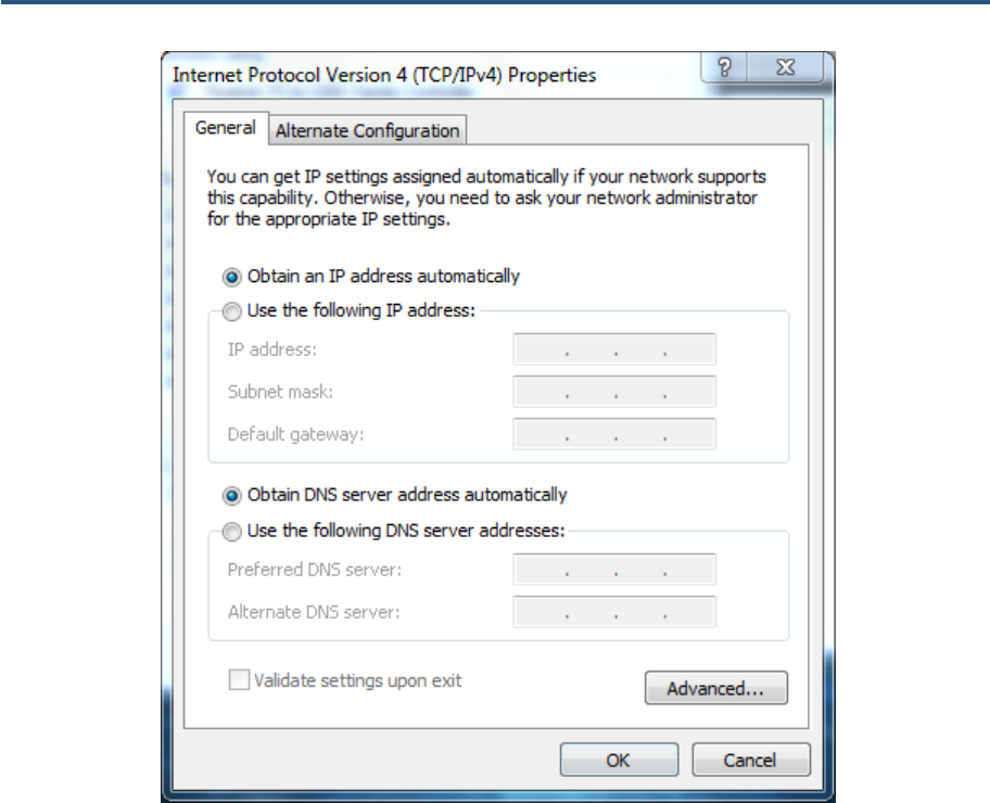
6. In the Internet Protocol Version 4 Properties dialog box, click Obtain an IP address
automatically to configure your computer for DHCP (see Figure 8).
Figure 8. Internet Protocol Properties Window
7. Click the OK button to save your changes and close the dialog box.
8. Click the OK button again to save your changes.
Figure 9. Local Area Connection Status Window
錯誤! 尚未定義樣式。
24
SMCD3GN2 Wireless Cable Modem Gateway Administrator Manual
Configuring Microsoft Windows 7
Use the following procedure to configure a computer running Microsoft Windows 7.
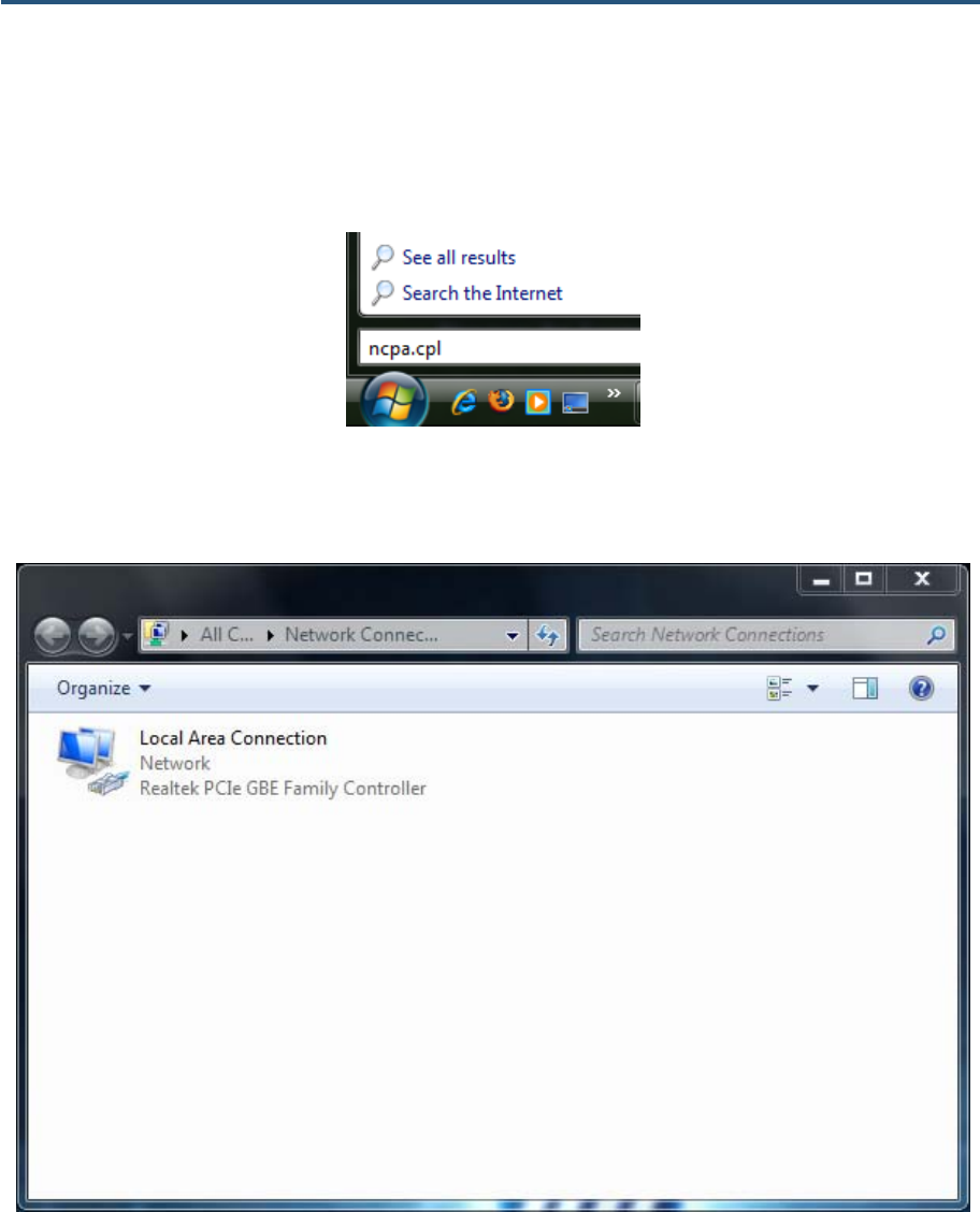
1. In the Start menu search box, type: ncpa.cpl
Figure 10. Typing ncpa.cpl in the Start Menu Box
The Network Connections List appears.
Figure 11. Example of Network Connections List
2. Right-click the Local Area Connection icon and click Properties.
3. In the Networking tab, click either Internet Protocol Version 4 (TCP/IPv4) or Internet
Protocol Version 6 (TCP/IPv6), and then click Properties.
錯誤! 尚未定義樣式。
25
SMCD3GN2 Wireless Cable Modem Gateway Administrator Manual
Figure 12. Local Area Network Connection Properties Dialog Box
4. In the properties dialog box, click Obtain an IP address automatically to configure your
computer for DHCP (see Figure 13).
錯誤! 尚未定義樣式。
26
SMCD3GN2 Wireless Cable Modem Gateway Administrator Manual
Figure 13. Properties Window
5. Click the OK button to save your changes and close the dialog box.
6. Click the OK button again to save your changes.
Configuring an Apple® Macintosh® Computer
The following procedure describes how to configure TCP/IP on an Apple Macintosh running
Mac OS 10.2. If your Apple Macintosh is running Mac OS 7.x or later, the steps you perform
and the screens you see may differ slightly from the following. However, you should still be
able to use this procedure as a guide to configuring your Apple Macintosh for TCP/IP.
a. Pull down the Apple Menu, click System Preferences, and select Network.
錯誤! 尚未定義樣式。
27
SMCD3GN2 Wireless Cable Modem Gateway Administrator Manual
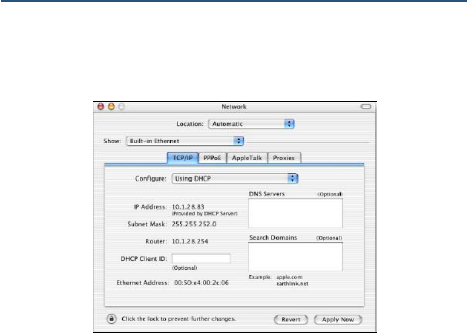
7. Verify that the NIC connected to the SMCD3GN3 is selected in the Show field.
8. In the Configure field on the TCP/IP tab, select Using DHCP (see Figure 14).
9. Click Apply Now to apply your settings and close the TCP/IP dialog box.
Figure 14. Selecting Using DHCP in the Configure Field

28
SMCD3GN2 Wireless Cable Modem Gateway Administrator Manual
4 Configuring the Gateway
This chapter describes how to use a Web browser to configure the Gateway.
The topics covered in this chapter are:
y Pre-configuration Guidelines (page 29)
y Accessing the Gateway’s Web Management (page 31)
y Understanding the Web Management Interface Screens (page 32)
y Web Management Interface Menus (page 33)

29
SMCD3GN2 Wireless Cable Modem Gateway Administrator Manual
Pre-configuration Guidelines
Before you configure the Gateway, observe the guidelines in the following sections.
Disabling Proxy Settings
Disable proxy settings in your Web browser. Otherwise, you will not be able to view the
Gateway’s Web-based configuration pages.
Disabling Proxy Settings in Internet Explorer
The following procedure describes how to disable proxy settings in Internet Explorer 5 and
later.
1. Start Internet Explorer.
2. On your browser’s Tool menu, click Options. The Internet Options dialog box appears.
3. In the Internet Options dialog box, click the Connections tab.
4. In the Connections tab, click the LAN settings button. The Local Area Network (LAN)
Settings dialog box appears.
5. In the Local Area Network (LAN) Settings dialog box, uncheck all check boxes.
6. Click OK until the Internet Options window appears.
7. In the Internet Options window, under Temporary Internet Files, click Settings.
8. For the option Check for newer versions of stored pages, select Every time I visit the
webpage.
9. Click OK until you close all open browser dialog boxes.
Disabling Proxy Settings in Firefox
The following procedure describes how to disable proxy settings in Firefox.
1. Start Firefox.
2. On your browser’s Tools menu, click Options. The Options dialog box appears.
3. Click the Advanced tab.
4. In the Advanced tab, click the Network tab.
5. Click the Settings button.
6. Click Direct connection to the Internet.
7. Click the OK button to confirm this change.

錯誤! 尚未定義樣式。
30
SMCD3GN2 Wireless Cable Modem Gateway Administrator Manual
Disabling Proxy Settings in Safari
The following procedure describes how to disable proxy settings in Safari.
1. Start Safari.
2. Click the Safari menu and select Preferences.
3. Click the Advanced tab.
4. In the Advanced tab, click the Change Settings button.
5. Choose your location from the Location list (this is generally Automatic).
6. Select your connection method. If using a wired connection, select Built-in Ethernet. For
wireless, select Airport.
7. Click the Proxies tab.
8. Be sure each proxy in the list is unchecked.
9. Click Apply Now to finish.
Disabling Firewall and Security Software
Disable any firewall or security software that may be running on your computer. For more
information, refer to the documentation for your firewall.
錯誤! 尚未定義樣式。
31
SMCD3GN2 Wireless Cable Modem Gateway Administrator Manual
Accessing the Gateway’s Web Management
After configuring your computer for TCP/IP and performing the preconfiguration guidelines
on the previous page, you can now easily configure the Gateway from the convenient Web-
based management interface. From your Web browser (Microsoft Internet Explorer version
5.5 or later), you will log in to the interface to define system parameters, change password
settings, view status windows to monitor network conditions, and control the Gateway and its
ports.
To access the SMCD3GN3 Wireless Cable Modem Gateway’s web-based management
screens, use the following procedure.
1. Launch a Web browser.
Note: The cable modem does not have to be online to configure the Gateway.
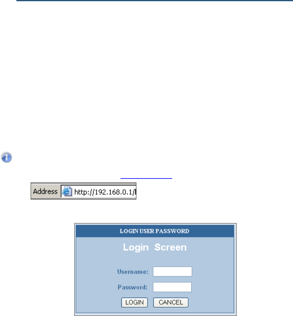
2. In the browser address bar, type http://192.168.0.1 and press the Enter key. For example:
The Login User Password screen appears (see Figure 15)
Figure 15. Login User Password Screen
3. In the Login User Password screen, enter the default administrator username and the
default administrator password provided by SMC Networks. Both the username and
password are case sensitive.
4. Click the Login button to access the Gateway. The Status page appears, showing
connection status information about the Gateway.
錯誤! 尚未定義樣式。
32
SMCD3GN2 Wireless Cable Modem Gateway Administrator Manual
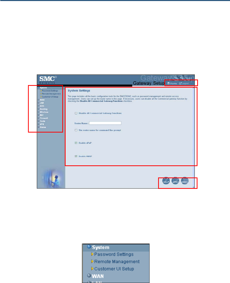
Understanding the Web Management Interface Screens
The left side of the management interface contains a menu bar you use to select menus for
configuring the Gateway. When you click a menu, information and any configuration settings
associated with the menu appear in the main area of the interface (see Figure 16). If the
displayed information exceeds what can be shown in the main area, scroll bars appear to
the right of the main area so you can scroll up and down through the information.
Figure 16. Main Areas on the Web Management Interface
Some menus have submenus associated with them. If you click a menu that has submenus,
the submenus appear below the menu. For example, if you click the System menu, the
submenus Password Settings, Remote Management, and Customer UI Setup appear
below the System menu (see Figure 17).
Figure 17. Example of System Submenus
The top-right side of the page contains a Home button that displays the Home (Status) page
and a Logout button for logging out of the Web management interface.
Main Area
Menu bar
Help, Apply, and
Cancel Buttons
Home and
Logout Buttons

錯誤! 尚未定義樣式。
33
SMCD3GN2 Wireless Cable Modem Gateway Administrator Manual
The bottom right side of the screen contains three buttons:
y Help displays online help
y Apply click this button to save your configuration changes to the displayed page
y Cancel click this button to discard any configuration changes made to the current page
Web Management Interface Menus and Submenus
Table 3 describes the menus and submenus in the Web management interface.
Note: Some menus and submenus described in this chapter may not
apply to your Gateway. Please check your Gateway’s GUI to see which
menus and submenus are available.
Table 3. Web Management Interface Menus and Submenus
Menus and Submenus Description See Page
System Lets you disable all commercial Gateway functions, define a router name, use the
router name at command prompts, and enable or disable UPnP and HNAP.
Submenus let you:
36
System > Password Settings • Define user and admin password settings, RADIUS authentication, TACACS+
authentication, and TACACS authentication. 38
System > Remote Management • Allow users to manage the Gateway remotely using the Gateway’s Web interface
and/or Telnet, and enable or disable remote management of the Gateway’s
administrator interface.
43
System > Customer UI Setup • Select which configuration options on the Gateway’s user configuration menus are
shown to or hidden from users. 44
WAN Lets you configure Wide Area Network (WAN) and Media Access Channel (MAC)
spoofing settings. The submenu lets you: 46
WAN > MAC Spoofing • Clone (“spoof”) the Gateway’s MAC address if necessary. 49
LAN Lets you configure settings for your public and private LAN, auto-negotiation, and
duplex mode. The submenu lets you: 50
LAN > Ether Switch Control • Specify fixed speed and duplex settings, and disable individual LAN ports. 53
LAN > Ether Access Control • Allow all EtherLAN client stations to access the Internet through the Gateway,
allow certain trusted EtherLAN client stations to access the Internet through the
Gateway, or deny certain trusted EtherLAN client stations from accessing the
Internet through the Gateway.
54
LAN > Additional Public LAN • Add more than one public subnet, except for 20.20.1, to the LAN interface. 58
LAN > Public LAN IP Access
Control • Block specific pubic IP addresses from accessing the Internet. 60
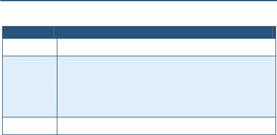
QoS Lets you configure Quality of Service (QoS) settings. If you enable QoS, the
following submenus become available for: 62
QoS > Port • Prioritizing performance of the four Gateway LAN ports. 64
錯誤! 尚未定義樣式。
34
SMCD3GN2 Wireless Cable Modem Gateway Administrator Manual
QoS > COS • Defining four queues to which the Class of Service (CoS) is mapped. 65
QoS > DSCP • Defining the QoS class queue to which the customized DSCP is mapped. 67
QoS > Queue • Specifying whether QoS behavior runs with strict or weighted priority. 69
QoS > DSCP Remarking • Defining the DSCP remarking action and mode. 71
Routing Lets you set up routing tables manually and automatically using the Routing
Information Protocol (RIP). Submenus let you: 73
Routing > Static Routes • Add static routes manually. 73
Routing > RIP Control • Configure how the Gateway adjusts to physical changes in the network’s layout
and exchange routing tables with other routers. 75
Routing > OSPF Control • Control how the Gateway uses the Open Shortest Path First (OSPS) protocol. 79
Wireless Lets you configure basic wireless settings, such as enabling or disabling wireless
operation, selecting wireless mode, and configuring the Service Set Identifier (SSID)
and channel settings. Submenus let you:
83
Wireless > Encryption • Use encryption to protect the data transmitted across your wireless network 85
Wireless > WPS • Enable or disable Wi-Fi Protected Setup (WPS). 88
Wireless > MAC Filtering • Allow all wireless client stations or only trusted PCs to connect over a wireless
connection. 91
Wireless > Advanced Settings • Configure advanced wireless settings for the Gateway. 93

錯誤! 尚未定義樣式。
35
SMCD3GN2 Wireless Cable Modem Gateway Administrator Manual
NAT Allows multiple users at your local site to access the Internet using a single pubic IP address. The
submenus let you:
NAT > Port Forwarding • Configure predefined and custom port forwarding settings to let Internet users
access local services such as the Web Server or FTP server at your local site. 95
NAT > 1-to-1 Mapping • Perform 1-to-1 mapping between global IP addresses on the cable modem WAN
interface and the private IP address on the LAN. 102
Firewall Lets you enable or disable the Gateway’s firewall. Submenus let you: 105
Firerwall > Access Control • Block traffic at the Gateway's LAN interfaces from accessing the Internet. 107
Firerwall > Special Application • Detect port triggers for detect multiple-session applications and allow them to
pass the firewall. 108
Firerwall > URL Blocking • Block access to certain Web sites from local computers by entering either a full
URL address or keywords of the Web site. 122
Firerwall > Schedule Rule • Define schedule rules that work with the Gateway’s URL blocking feature. 124
Firerwall > Email/Syslog Alert • Send email notifications or add entries to the syslog when traffic is blocked,
attempts are made to intrude onto the network, and local computers try to access
block URLs.
125
Firerwall > DMZ • Configure a local client computer for unrestricted two-way Internet access by
defining it as a Virtual DMZ host. 129
Tools Provides the following submenus with utilities for performing the following activities:
Tools > Configuration Tools Back up and restore Gateway configuration settings locally and remotely over the
WAN, and restore Gateway factory default settings. 130
Tools > Reboot Reboot the Gateway. 137
Tools > Diagnostics Perform trace route and ping diagnostic operations. 138
Tools > SNTP Client Configure the Gateway to act as a SNTP client. 144
VPN Lets you enable or disable the Gateway’s VPN functions. When VPN functions are
enabled, submenus let you: 145
VPN > Access Control • Allow PC clients behind the Gateway to access the IPSec VPN tunnel. 147
VPN > IPsec Tunnel
Configuration • Define up to five tunnels and view, clear, refresh, and save the VPN log. 148
VPN > PPTP/L2TP
Configuration • Set up to 50 Point-to-Point Tunneling Protocol (PPTP) / Layer Two Tunneling
Protocol (L2TP) user accounts and define a pre-shared phrase. 153
Status Shows the connection status of the Gateway interfaces, firmware, hardware version
numbers, illegal attempts to access your network, and information about DHCP
client PCs current connected to the Gateway. The submenu lets you:
156
Status > Cable Status • View cable initialization procedures, and cable downstream and upstream status. 158
錯誤! 尚未定義樣式。
36
SMCD3GN2 Wireless Cable Modem Gateway Administrator Manual
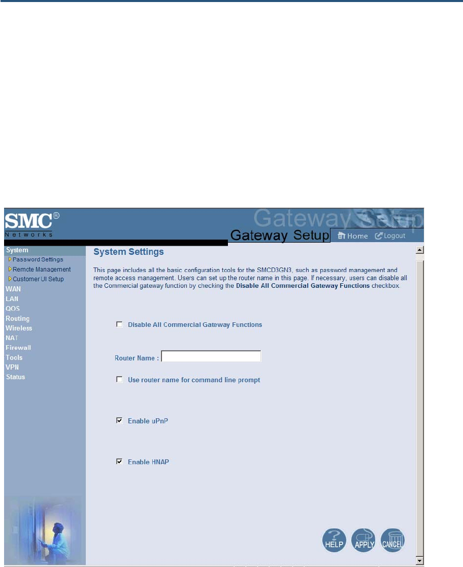
System Settings Menu
The System Settings menu lets you:
y Enable or disable all commercial Gateway functions
y Define the Gateway’s name and enable it for command line prompt
y Enable or disable UPnP and HNAP
To access the System Settings menu, click System in the menu bar. Figure 18 shows an
example of the menu and Table 4 describes the setting you can select.
Figure 18. System Settings Menu
錯誤! 尚未定義樣式。
37
SMCD3GN2 Wireless Cable Modem Gateway Administrator Manual
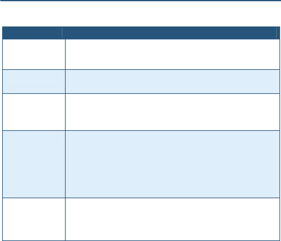
Table 4. System Settings Menu Option
Option Description
Disable All Commercial
Gateway Functions Enables or disables all commercial Gateway functions.
• Checked = all commercial Gateway functions are disabled.
• Unchecked = all commercial Gateway functions are enabled. (default)
Router Name The name you want to assign to the Gateway. Assign a name so that this device will not be confused
with other devices on your wireless network. We recommend you use a name that is meaningful to you
so you can identify the Gateway easily.
Use router name for
command line prompt Determines whether the router name you specified appears in DOS command line prompts (for
example, if you Telnet into the Gateway).
• Checked = router name appears in command line prompts.
• Unchecked = router name foes not appear in command line prompts. (default)
Enable UPnP Configures the Gateway as a Universal Plug and Play (UPnP) Internet gateway. UPnP allows for
dynamic connectivity between devices on a network. A UPnP-enabled device like the Gateway can
obtain an IP address, advertise its capabilities, learn about other connected UPnP devices and then
communicate directly with those devices. The same device can end its connection cleanly when it
wishes to leave the UPnP community. The intent of UPnP is to support zero-configuration, "invisible"
networking of devices including intelligent appliances, PCs, printers, and other smart devices using
standard protocols.
• Checked = UPnP is enabled on the Gateway. (default)
• Unchecked = UPnP is disabled on the Gateway.
Enable HNAP Configures the Gateway as a Home Network Administration Protocol (HNAP) device. HNAP allows the
Gateway to be configured and managed by remote entities, such as Network Magic or any software
application that discovers and manages network devices.
• Checked = HNAP is enabled on the Gateway.
• Unchecked = HNAP is disabled on the Gateway. (default)

錯誤! 尚未定義樣式。
38
SMCD3GN2 Wireless Cable Modem Gateway Administrator Manual
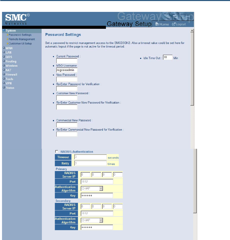
Password Settings Menu
The Password Settings menu lets you change the Gateway’s default administrator
username and password and the user’s password.
The Password Settings menu also lets you change the number of minutes of inactivity that
can occur before your Web management session times out automatically. The default
setting is 10 minutes.
In addition, you can configure Remote Authentication Dial In User Service (RADIUS),
Terminal Access Controller Access-Control System Plus (TACACS+) , and Terminal Access
Controller Access-Control System (TACACS) configuration settings.
y RADIUS is a networking protocol that provides centralized authentication, authorization,
and accounting management for computers to connect and use a network service
y TACACS is a remote authentication protocol used to communicate with an
authentication server commonly used in UNIX networks. TACACS lets a remote access
server communicate with an authentication server determine whether the user has
access to the network.
y TACACS+ is a Cisco-proprietary protocol that provides access control for the Gateway
and other networked computing devices via one or more centralized servers. TACACS+
provides separate authentication, authorization, and accounting services.
To access the Password Settings menu, click System in the menu bar and then click the
Password Settings submenu. Figure 19 shows an example of the menu and Table 5
describes the settings you can select.
錯誤! 尚未定義樣式。
39
SMCD3GN2 Wireless Cable Modem Gateway Administrator Manual
錯誤! 尚未定義樣式。
40
SMCD3GN2 Wireless Cable Modem Gateway Administrator Manual
Figure 19. Password Settings Menu

錯誤! 尚未定義樣式。
41
SMCD3GN2 Wireless Cable Modem Gateway Administrator Manual
Table 5. Password Settings Menu Options
Option Description
Current Password Enter the current case-sensitive administrator password. For security purposes, every typed
character appears as a dot (y). The default password is not shown for security purposes.
MSO Username Enter the current new case-sensitive administrator username.
New Password Enter the new case-sensitive administrator password you want to use. A password can
contain up to 32 alphanumeric characters. Spaces count as password characters. For security
purposes, every typed character appears as a dot (y).
Re-Enter Password for Verification Enter the same case-sensitive administrator password you typed in the New Password field.
For security purposes, every typed character appears as a dot (y).
Commercial New Password Enter the new case-sensitive password your commercial users will use to log in to the
Gateway Web management interface. A password can contain up to 32 alphanumeric
characters. Spaces count as password characters. For security purposes, every typed
character appears as a dot (y). If you leave this field blank, the default user password will be
password.
Re-Enter Commercial New
Password for Verification Enter the same case-sensitive user password you typed in the Commercial New Password
field. For security purposes, every typed character appears as a dot (y).
Customer New Password Enter the new case-sensitive password your customers will use to log in to the Gateway Web
management interface. A password can contain up to 32 alphanumeric characters. Spaces
count as password characters. For security purposes, every typed character appears as a dot
(y). If you leave this field blank, the default user password will be password.
Re-Enter Customer New Password
for Verification Enter the same case-sensitive user password you typed in the Customer New Password
field. For security purposes, every typed character appears as a dot (y).
Idle Time Out Your Web management interface sessions timeout after 10 minutes of idle time. To change
this duration, enter a new timeout value.
RADIUS Authentication To enable RADIUS authentication, check this box and then select the options for the primary
and secondary authentication servers.
Timeout Amount of time the Gateway waits for a response from the RADIUS servers before it tries to
connect to the RADIUS servers again. Default is 3 seconds.
Retry Maximum number of connection attempts the Gateway makes to connect to the RADIUS
servers before giving up. Default is 3.
Primary/Secondary For the primary and secondary authentication servers, enter the:
• IP address of the RADIUS servers.
• Port number that RADIUS uses for authentication. Default is 1812.
• Authentication algorithm used for authentication. Choices are CHAP, MS-CHAP, and MS-
CHAPv2. Default is CHAP.
• Secret shared between the Gateway and RADIUS servers. For security purposes, every
typed character appears as a dot (y).
錯誤! 尚未定義樣式。
42
SMCD3GN2 Wireless Cable Modem Gateway Administrator Manual
Option Description
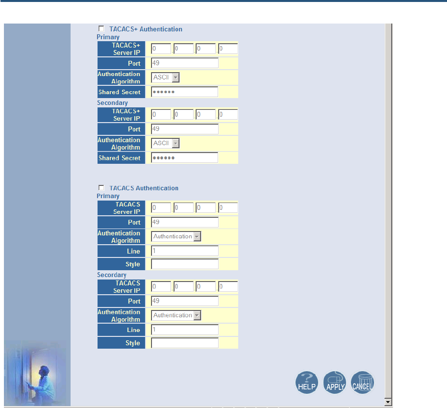
TACACS+ Authentication To enable TACACS+ authentication, check this box and then select the options for the
primary and secondary authentication servers:
• IP address of the TACACS+ servers.
• Port number that TACACS+ uses for authentication. Default is 49.
• Authentication algorithm used for authentication. Choices are ASCII, PAP, and CHAP.
Default is ASCII for the primary server and ASCII for the secondary server.
• Secret shared between the Gateway and TACACS+ servers. For security purposes, every
typed character appears as a dot (y).
TACACS Authentication To enable TACACS authentication, check this box and then select the options for the primary
and secondary authentication servers:
• IP address of the TACACS+ servers.
• Port number that TACACS uses for authentication. Default is 49.
• Authentication algorithm used for authentication. Choices are Authentication and Login.
Default is Authentication.
• Line the request is for. Default is 1.
• Style of authentication to be performed.
錯誤! 尚未定義樣式。
43
SMCD3GN2 Wireless Cable Modem Gateway Administrator Manual
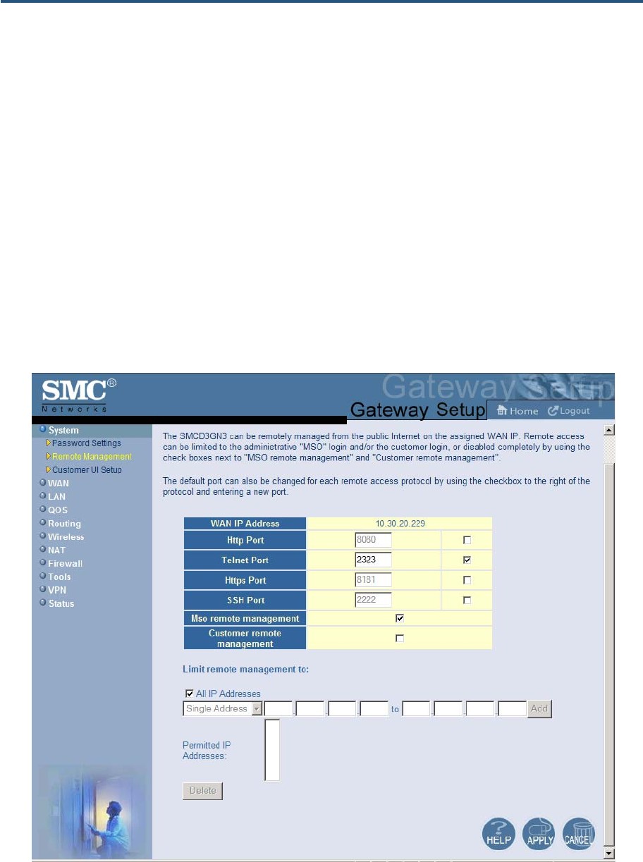
Remote Management Menu
Administrative users can use the Gateway’s Web-based management or Telnet to manage
the device remotely using the public Internet.
y To use Web-based management, users specify the WAN IP address and remote
management port in the URL entered in the Browser’s address field
y For Telnet, users specify the WAN IP address and the remote Telnet management port
Using the Remote Management menu, you can enable HTTP, Telnet, HTTPS, and SSH and
specify the port numbers for each of these settings. You can also limit remote management
to specific IP addresses.
To access the Remote Management menu, click System in the menu bar and then click the
Remote Management submenu in the menu bar. Figure 20 shows an example of the menu
and Table 6 describes the settings you can select.
Figure 20. Remote Management Menu
錯誤! 尚未定義樣式。
44
SMCD3GN2 Wireless Cable Modem Gateway Administrator Manual
Table 6. Remote Management Settings Menu Options
Option Description
WAN IP Address IP address used to access the Gateway’s Web management interface via the Internet. For
example, if the WAN IP address is 123.45.67.8 and the Web management port is 8080,
remote users type http://123.45.67.8:8080 to access the Web management interface. To
change the value shown, check the box to the right of this option and enter a new value.
Http Port Port number used to access the Gateway’s Web management interface. Range is from 1024
to 65535. Default is 8080. To change the value shown, check the box to the right of this option
and enter a new value.
Telnet Port Port number used to Telnet into the Gateway. Range is from 1 to 65535. Default is 2323. To
change the value shown, check the box to the right of this option and enter a new value.
Https Port Port number used to access the Gateway via a secure HTTPS connection. Default is 8181.
To change the value shown, check the box to the right of this option and enter a new value.
SSH Port Port number used to access the Gateway via a Secure Sockets Shell (SSH) connection.
Default is 2222. To change the value shown, check the box to the right of this option and
enter a new value.
Mso remote management Enables or disables remote access to administrator configuration options.
• Checked = administrator remote management is enabled. (default)
• Unchecked = administrator remote management is disabled.
Customer remote management Enables or disables remote access to user configuration options.
• Checked = user remote management is enabled.
• Unchecked = user remote management is disabled. (default)
Limit remote management to By default, enabling remote management makes the device available to all IP addresses. To
limit remote management to a subset of IP addresses, uncheck All IP addresses, select
Single Address or Address Range from the drop-down list, enter the IP address or address
range in the fields, and click Add. The IP addresses appear in Permitted IP Addresses. To
delete an IP address or address range, click the address in Permitted IP Addresses and
click Delete. No precautionary message appears before you delete an IP address.
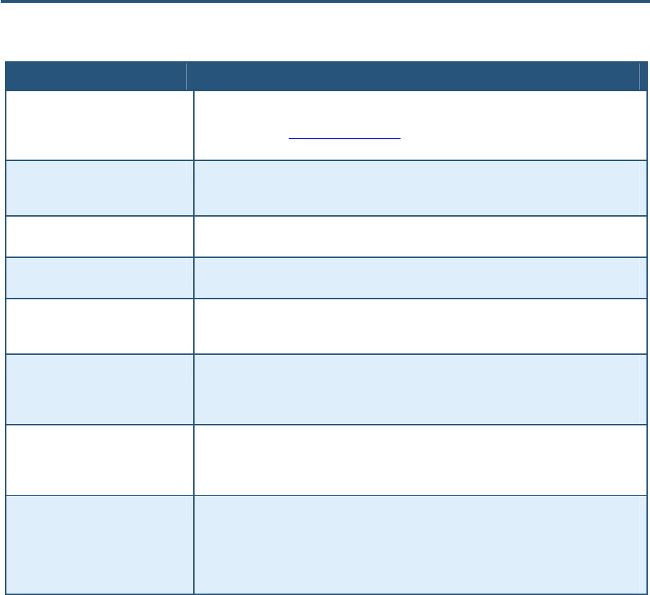
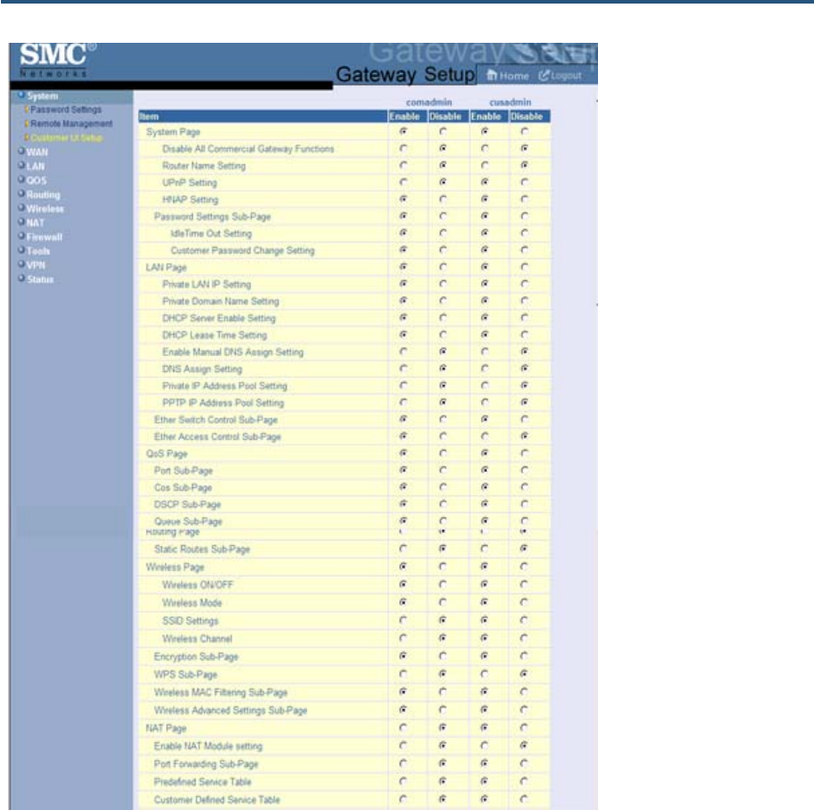
Customer UI Setup Menu
The Customer UI Setup menu lets you select which menus, submenus, and configuration
options are shown to (Enable) or hidden from (Disable) users. Using this menu, for example,
you can hide options that, if changed by users, could adversely affect the Gateway. These
settings do not affect the configuration options displayed for administrators. A Reset to
Defaults button at the bottom-left side of the menu lets you return the parameters on this
menu to their factory default settings.
To access the Customer UI Setup menu, click System in the menu bar and then click the
Customer UI Setup submenu in the menu bar. Figure 21 shows an example of the menu.
錯誤! 尚未定義樣式。
45
SMCD3GN2 Wireless Cable Modem Gateway Administrator Manual
錯誤! 尚未定義樣式。
46
SMCD3GN2 Wireless Cable Modem Gateway Administrator Manual
Figure 21. Customer UI Setup Menu
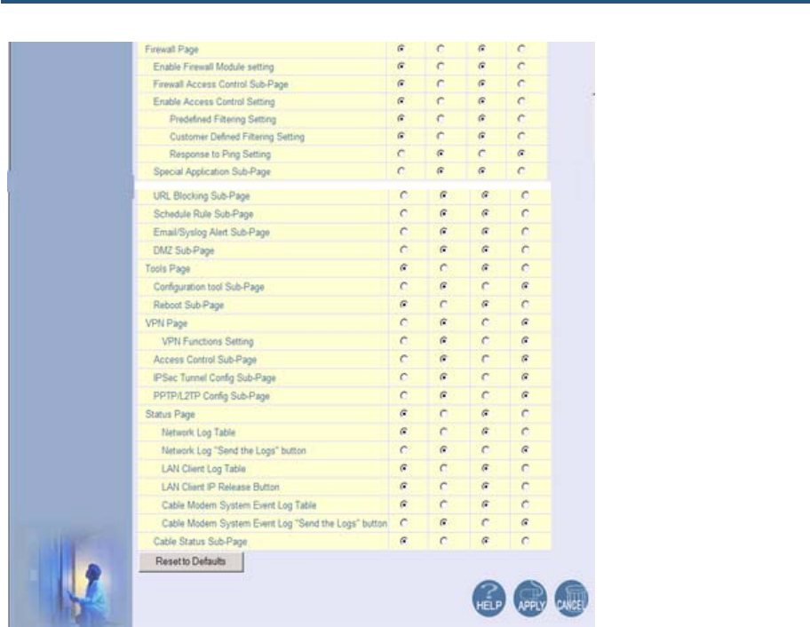
WAN Settings Menu
The Gateway can connect to the cable service provider using either a static IP address or an
IP address automatically assigned by a Dynamic Host Configuration protocol (DHCP) server.
Using the WAN Settings menu, you can assign your own static WAN IP and DNS addresses
to the Gateway. By default, both options are disabled, allowing the Gateway to obtain these
settings automatically from a DHCP server.
To access the WAN Settings menu, click WAN in the menu bar. Figure 22 shows an
example of the menu and Table 7 describes the settings you can select.
錯誤! 尚未定義樣式。
47
SMCD3GN2 Wireless Cable Modem Gateway Administrator Manual
Figure 22. WAN Settings Menu
錯誤! 尚未定義樣式。
48
SMCD3GN2 Wireless Cable Modem Gateway Administrator Manual
Table 7. WAN Settings Menu Options
Option Description
Do you want to assign your own
WAN IP address? By default, this option is set to No. Cable modem providers typically use dynamic assignment
of IP addresses. To assign a static WAN IP address to the Gateway and make the WAN fields
below this option available, click Yes.
Use public LAN IP as the WAN IP Check this box if you want to use the static public LAN IP address for the WAN IP address.
This checkbox is available if Do you want to assign your own WAN IP address is set to
Yes.
WAN IP Address Enter a unique static IP address the Gateway.
WAN IP Subnet Mask Enter the subnet mask for the Gateway
WAN Gateway IP Address Enter the Gateway IP address.
Release/Renew button Click this button to release and then renew the Gateway’s IP address. This button is available
for DHCP only. It is gray and unavailable when Do you want to assign your own WAN IP
address is set to Yes.
Do you want to assign your own
DNS address? By default, this option is set to No. Cable modem providers typically use dynamic assignment
of IP addresses. To assign your own IP addresses to primary and secondary DNS servers
and make the DNS fields below this option available, click Yes.
Primary DNS Enter a primary DNS server IP address.
Secondary DNS Enter the secondary DNS server IP address.
Host Name This setting is optional. If you will require a host name for DHCP requests, enter it here.
錯誤! 尚未定義樣式。
49
SMCD3GN2 Wireless Cable Modem Gateway Administrator Manual
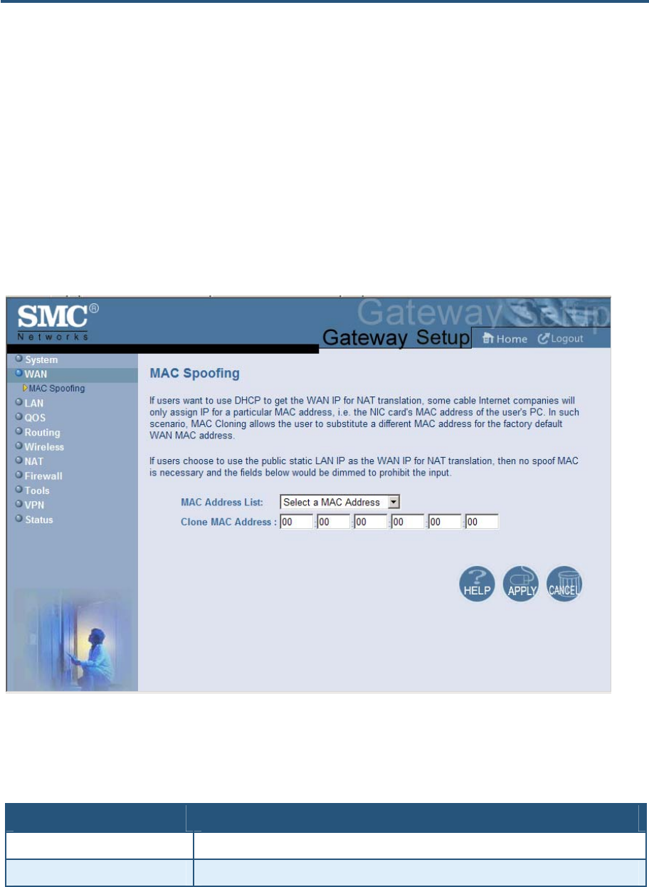
MAC Spoofing Menu
If you need to re-register your MAC address, you can use the MAC Spoofing menu to clone
(or “spoof”) the Gateway’s registered MAC address as necessary.
If you use the public static LAN IP address as the WAN IP for NAT translation, no MAC
spoofing is necessary,
To access the MAC Spoofing menu, click WAN in the menu bar and then click the MAC
Spoofing submenu. Figure 23 shows an example of the menu and Table 8 describes the
settings you can select.
Figure 23. MAC Spoofing Menu
Table 8. MAC Spoofing Menu Options
Option Description
MAC Address List Select the MAC address you want to spoof.
Clone MAC Address Clone the MAC address of the NIC communicating with the cable modem.

錯誤! 尚未定義樣式。
50
SMCD3GN2 Wireless Cable Modem Gateway Administrator Manual
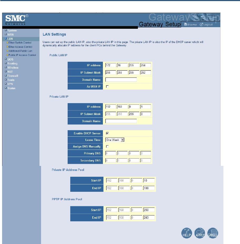
LAN Settings Menu
IP addresses are close to being used up and thus very hard to get. One solution to this
problem is "private" IP addresses. Private IP addresses are ranges of IP addresses set
aside expressly for use by a company or other entity internally. Private IP addresses are
non-routable and, therefore, cannot be used to connect directly to the Internet.
Some of the advantages of private IP addresses include:
y Increased security, since private IP addresses are not routable across the Internet
y You conserve the world-wide pool of IP addresses
y You do not have to register or pay for these IP addresses in any way
The LAN Settings menu lets you configure private LAN IP settings and private IP address
pools for the Gateway. To access the LAN Settings menu, click LAN in the menu bar. Figure
24 shows an example of the menu and Table 9 describes the settings you can select.
錯誤! 尚未定義樣式。
51
SMCD3GN2 Wireless Cable Modem Gateway Administrator Manual
Figure 24. LAN Settings Menu
錯誤! 尚未定義樣式。
52
SMCD3GN2 Wireless Cable Modem Gateway Administrator Manual
Table 9. LAN Settings Menu Options
Option Description
Pubic LAN IP
IP Address IP address of the Gateway’s private LAN settings. Default IP address is 192.168.0.1. if you
change this setting, the Gateway reboots after displaying a message.
IP Subnet Mask Subnet mask of the Gateway’s private LAN settings. Default subnet mask is 255.255.255.0.
Domain Name Domain name of the Gateway’s private LAN settings.
As WAN IP Check this box if you want to use the static public LAN IP address for the WAN IP address.
Private LAN IP
IP Address IP address of the Gateway’s private LAN settings. Default IP address is 192.168.0.1. if you
change this setting, the Gateway reboots after displaying a message.
IP Subnet Mask Subnet mask of the Gateway’s private LAN settings. Default subnet mask is 255.255.255.0.
Domain Name Domain name of the Gateway’s private LAN settings.
Enable DHCP Server Enables or disables the DHCP server to allow automatic allocation of IP addresses to LAN
client PCs.
• Checked = DHCP server is enabled. (default)
• Unchecked = DHCP server is disabled.
Lease Time Amount of time a DHCP network user is allowed connection to the Gateway with their current
dynamic IP address. Default is One Week. This option is available when Enable DHCP
Server is checked.
Assign DNS Manually Enables or disables the DHCP server to allow automatic allocation of primary and secondary
IP addresses for DSN servers on the LAN.
• Checked = use static IP addresses for primary and secondary DNS servers. If checked,
enter the IP addresses of the primary and secondary DNS server in the Primary DNS and
Secondary DNS fields.
• Unchecked = allocate IP addresses for primary and secondary DNS servers automatically.
(default)
Primary DNS Static IP address of the primary DNS server. This option is available when Assign DNS
Manually is checked.
Secondary DNS Static IP address of the secondary DNS server. This option is available when Assign DNS
Manually is checked.
Private IP Address Pool
Start IP Starting IP address range for the pool of allocated for private IP addresses.
End IP Ending IP address range for the pool of allocated for private IP addresses.
PPTP IP Address Pool
Start IP Starting IP address range for the pool of allocated for point-to-point tunneling protocol (PPTP)
IP addresses.
End IP Ending IP address range for the pool of allocated for PPTP IP addresses.
錯誤! 尚未定義樣式。
53
SMCD3GN2 Wireless Cable Modem Gateway Administrator Manual
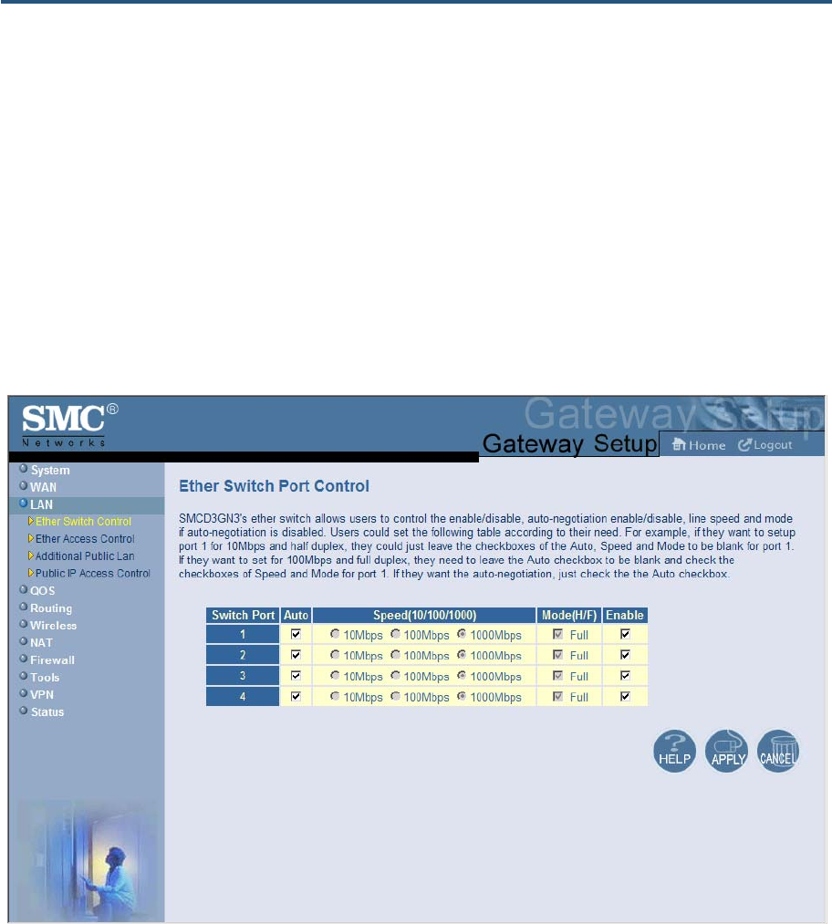
Ether Switch Port Control Menu
By default, the Gateway LAN ports are enabled to auto-negotiate the highest supported
speed and appropriate duplex mode. If these settings prevent the Gateway from
successfully connecting with other devices, you can use the Ether Switch Port Control menu
to configure the Gateway to use fixed speed and duplex settings. The Ether Switch Port
Control menu also let you disable the individual LAN ports. For your convenience, each port
can be configured independently of the other LAN ports on the Gateway.
To access the Ether Switch Control menu, click LAN in the menu bar and then click the
Ether Switch Control submenu in the menu bar. Figure 25 shows an example of the menu.
Figure 25. Ether Switch Port Control Menu

錯誤! 尚未定義樣式。
54
SMCD3GN2 Wireless Cable Modem Gateway Administrator Manual
The following procedure describes how to change the settings in the Ether Switch Port
Control menu.
1. To change a port from auto-negotiation to a fixed speed and duplex setting:
a. Uncheck the Auto check box for the port.
b. Under Speed (10/100/1000), click the radio that corresponds to the fixed speed you
want to use for that port.
c. Under the Mode H/F column, leave the check mark for full-duplex mode or uncheck it
for half-duplex mode.
2. To disable a port, regardless of the auto-negotiation and duplex settings, uncheck Enable
for the port.
3. Click Apply.
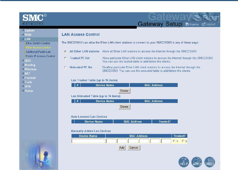
LAN Access Control Menu
Using the LAN Access Control menu, you can:
y Allow all EtherLAN client stations to access the Internet through the Gateway. This is the
default setting.
y Allow certain trusted EtherLAN client stations to access the Internet through the
Gateway. You use the add up to 16 trusted clients.
y Deny certain trusted EtherLAN client stations from accessing the Internet through the
Gateway. You use the add up to 16 untrusted clients.
To access the LAN Access Control menu, click LAN in the menu bar and then click the
Ether Access Control submenu in the menu bar. Figure 26 shows an example of the menu.
錯誤! 尚未定義樣式。
55
SMCD3GN2 Wireless Cable Modem Gateway Administrator Manual
Figure 26. LAN Access Control Menu

錯誤! 尚未定義樣式。
56
SMCD3GN2 Wireless Cable Modem Gateway Administrator Manual
Controlling LAN Access
By default, All EtherLAN LAN stations is selected at the top of the menu. This setting
allows all client stations to access the Internet through the Gateway. To restrict LAN access,
click one of the following radio buttons and click Apply:
y Trusted PC List = restricts Internet access through the Gateway to client stations in the
Lan Trusted Table. To add client station to this table, see “Adding and Deleting Trusted
Client Stations”, below.
y Untrusted PC list = prevents client stations in the Lan Untrusted Table from accessing
the Internet through the Gateway. To add client stations to this table, see “Adding and
Deleting Untrusted Client Stations” on page 57.
Adding and Deleting Trusted Client Stations
To restrict Internet access through the Gateway to certain trusted EtherLAN client stations,
define the client stations as trusted clients. Using this procedure you can define up to 16
trusted client stations.
1. Click Trusted PC list at the top of the menu.
2. To add client stations that the Gateway automatically learned on the network, perform the
following steps under Auto-Learned Lan Devices:
a. Click a client station that the Gateway learned automatically.
b. Under Trusted?, click Y.
c. Click Add. The client station is added to the Lan Trusted Table.
d. To add more auto-learned client stations (up to 16), repeat steps 2a through 2c.
3. To manually add trusted client stations, perform the following steps under Manually-
Added Lan Devices:
a. Under Device Name, enter a name for the device.
b. Under MAC Address, enter the MAC address of the device.
c. Under Trusted?, click Y.
d. Click Add to add the client station to the Lan Trusted Table.
e. To manually add more client stations (up to 16), repeat steps 3a through 3d.

錯誤! 尚未定義樣式。
57
SMCD3GN2 Wireless Cable Modem Gateway Administrator Manual
4. To delete client stations from the Lan Trusted Table, click the radio button corresponding
to the client station you want to delete and click the Delete button. A precautionary
message does not appear before deleting a client station.
5. To enforce this policy, click Trusted PC list at the top of the menu.
6. When you finish, click Apply.
Adding and Deleting Untrusted Client Stations
To prevent certain trusted EtherLAN client stations from accessing the Internet through the
Gateway, define the client stations as untrusted clients. Using this procedure you can define
up to 16 untrusted client stations
1. Click Untrusted PC list at the top of the menu.
2. To add client stations that the Gateway automatically learned on the network, perform the
following steps under Auto-Learned Lan Devices:
a. Click a client station that the Gateway learned automatically.
b. Under Trusted?, click N.
c. Click Add to add the client station to the Lan Untrusted Table.
d. To add more auto-learned client stations, repeat steps 2a through 2c.
3. To manually add client stations, perform the following steps under Manually-Added Lan
Devices:
a. Under Device Name, enter the name of the device.
b. Under MAC Address, enter the MAC address of the device.
c. Under Trusted?, click N.
d. Click Add to add the client station to the Lan Untrusted Table.
e. To add more client stations manually, repeat steps 3a through 3d.
4. To delete client stations from the untrusted list, in the Lan Untrusted Table. click the radio
button corresponding to the client station you want to delete and click the Delete button. A
precautionary message does not appear before deleting an untrusted client station.
5. To enforce this policy, click Untrusted PC list at the top of the menu.
6. When you finish, click Apply.
錯誤! 尚未定義樣式。
58
SMCD3GN2 Wireless Cable Modem Gateway Administrator Manual
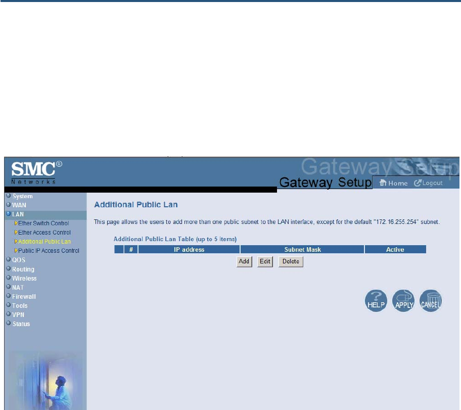
Additional Public Lan Menu
Using the Additional Public Lan menu, you can add more than one public subnet to the LAN
interface.
To access the Additional Public Lan menu, click LAN in the menu bar and then click the
Additional Public Lan submenu in the menu bar. Figure 27 shows an example of the menu.
Figure 27. Additional Public Lan Menu
錯誤! 尚未定義樣式。
59
SMCD3GN2 Wireless Cable Modem Gateway Administrator Manual
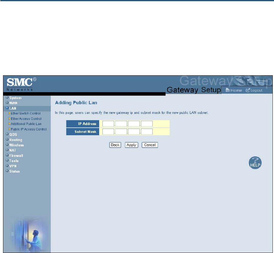
Adding Public Subnets
Using the following procedure, you can add up to 5 public subnets to the LAN interface.
1. In the Additional Pubic LAN menu, click the Add button The Adding Public Lan menu in
Figure 28 appears.
Figure 28. Adding Public Lan Menu
2. In the IP Address row, enter the IP address for the new public subnet.
3. In the Subnet Mask row, add the subnet mask for the new public subnet.
4. Click Apply to add the IP address and subnet. (Or click Back to return to the previous
menu or Cancel to cancel the operation .) If you clicked Apply, the IP address and subnet
mask are added to the Additional Public Lan Table.
5. By default the IP address and subnet you specified are active. To make then inactive,
uncheck the check box below Active.
6. Click Apply in the Additional Public Lan menu to save your settings.
7. To add more public subnets (up to 5), repeat steps 1 through 6.
錯誤! 尚未定義樣式。
60
SMCD3GN2 Wireless Cable Modem Gateway Administrator Manual
8. To change the settings for a subnet, click the radio button to the left of the subnet you want
to change and click the Edit button. When the Adding Public Lan menu appears, edit the
IP address and subnet mask as necessary and click Apply. Click Apply in the Additional
Public Lan menu to save your settings.
9. To delete a subnet, click the radio button to the left of the subnet you want to delete and
click the Delete button. No precautionary message appears before you delete a subnet.
Click Apply in the Additional Public Lan menu to save your settings.
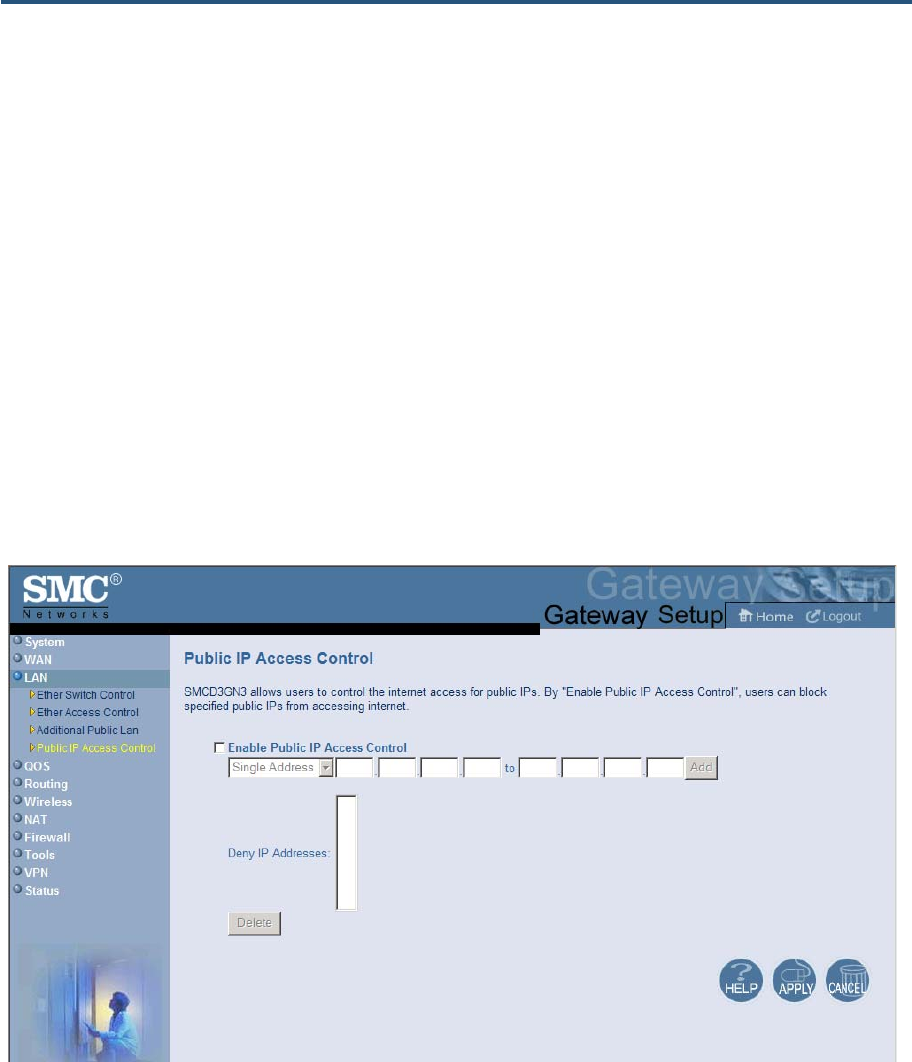
Public IP Access Control Menu
Using the Public IP Access Control menu, you can block specific pubic IP addresses from
accessing the Internet.
To access the Public IP Access Control, click LAN in the menu bar and then click the Public
IP Access Control submenu in the menu bar. Figure 29 shows an example of the menu
and Table 10 describes the settings you can select.
Figure 29. Public IP Access Control Menu
錯誤! 尚未定義樣式。
61
SMCD3GN2 Wireless Cable Modem Gateway Administrator Manual
Table 10. Public IP Access Control Menu Options
Option Description
Enable Public IP
Access Control Check this check box to make the fields on this page available.
Single Address /
Address Range From the first drop-down list, select whether you want to block a single IP address or a range of IP
addresses.
• If you select Single Address, type the four octets of the IP address you want to block. The second set
of four fields in unavailable.
• If you select Address Range, in the first four fields, type the first four octets of the IP address in the
starting IP address range you want to block. In the last four fields, type the last four octets of the IP
address in the ending IP address you want to block. The IP address or address range appears in the
Deny IP Addresses list.
Delete To remove an IP address or address range from the Deny IP Addresses list, click the IP address or
address range and click Delete.

錯誤! 尚未定義樣式。
62
SMCD3GN2 Wireless Cable Modem Gateway Administrator Manual
QoS Settings Menu
Quality of Service (QoS) refers to a collection of techniques for identifying data whose
delivery across the network is time sensitive, and managing its delivery through both
bandwidth allocation and prioritization schemes
Using the QoS Settings menu, you can enable the Gateway’s QoS module to provide
guarantees on the ability of the network to deliver predictable results. To access the QoS
menu, click QOS in the menu bar. Figure 30 shows an example of the menu.
By default, QoS is enabled. To enable the Gateway’s QoS module, check Enable QOS
Module and click Apply. To disable the Gateway’s QoS module, uncheck Enable QOS
Module and click Apply.
If you enable the Gateway’s QoS module, the following submenus appear under QOS in the
menu bar:
y Port - lets you configure the priority queue to which the switch port is mapped. See page
64.
y COS - lets you define four queues to which the CoS is mapped. See page 65.
y DSCP - lets you define the QoS class queue to which the customized DSCP is mapped.
See page 67.
y Queue - lets you specify whether QoS behavior runs with strict or weighted priority. See
page 69.
y DSCP Remarking - lets you define the DSCP remarking action and mode. See page 71.
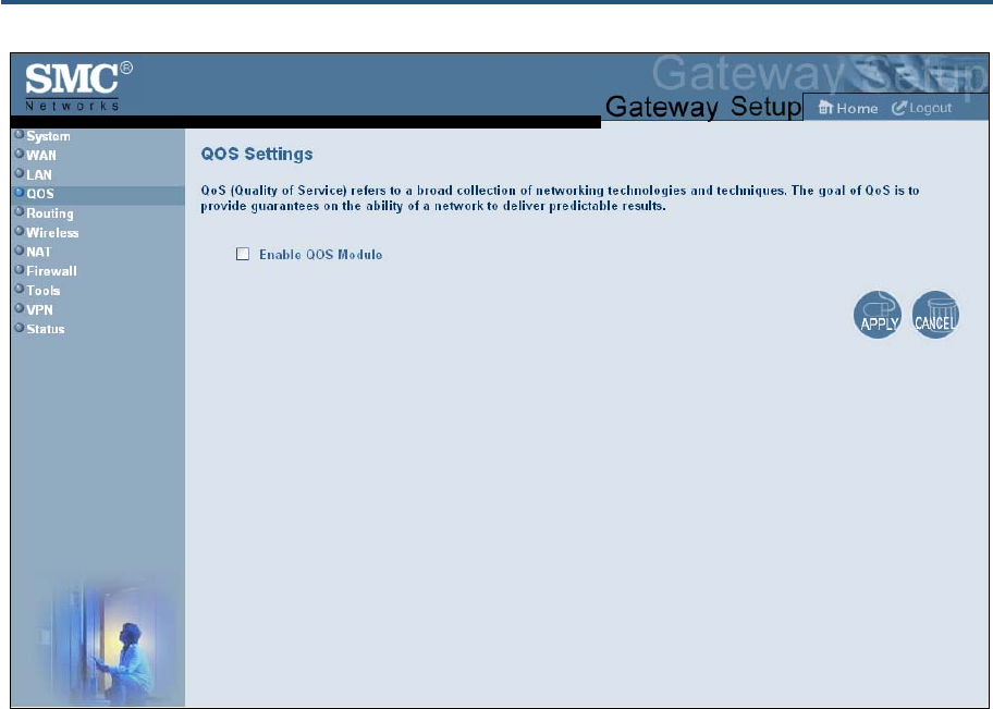
錯誤! 尚未定義樣式。
63
SMCD3GN2 Wireless Cable Modem Gateway Administrator Manual
Figure 30. QoS Settings Menu
錯誤! 尚未定義樣式。
64
SMCD3GN2 Wireless Cable Modem Gateway Administrator Manual
Port Based QoS Menu
The Port Based QoS menu lets you prioritize performance of the four Gateway LAN ports.
To access the Port Based QoS menu, click QOS in the menu bar and then click the Port
submenu in the menu bar. Figure 31 shows an example of the menu.
Note: The Port submenu is not available in the menu bar if Enable QOS Module
is not checked in the QoS Settings menu (see page 62).
Figure 31. Port Based QoS Menu
To define port-based QoS settings:
1. Check Enable Port Based QOS.
2. For each port, select a priority queue number from 0 to 3. Higher priority values are
evaluated as being of higher importance than lower priority values.
3. Click Apply.

錯誤! 尚未定義樣式。
65
SMCD3GN2 Wireless Cable Modem Gateway Administrator Manual
CoS Settings Menu
Given that there will always be points in the network where multiple traffic streams merge or
where network links will change speed and capacity, it is important to move traffic on the
basis of relative importance. Without CoS prioritization, less important traffic can consume
network bandwidth and slow down or halt the delivery of more important traffic. For example,
without CoS, most traffic received by the Gateway is forwarded with the same priority it had
upon entering the Gateway. In many cases, such traffic is ‘‘normal’’ priority and competes for
bandwidth with all other normal-priority traffic, regardless of its relative importance to your
requirements. CoS helps to keep the most important network traffic moving at an acceptable
speed, regardless of current bandwidth usage. This means you can manage available
bandwidth so that the switch transmits the most important traffic first.
The CoS Settings menu lets you configure a CoS priority of 0 through 7 for an outbound
packet. When the packet is then sent to a port, the CoS priority determines which outbound
queue the packet uses. After configuring CoS priority for outbound packets, use this menu to
map the classes of service to the Gateway’s four ports.
To access the CoS Settings menu, click QOS in the menu bar and then click the CoS
submenu in the menu bar. Figure 32 shows an example of the menu.
Note: The COS submenu is not available in the menu bar if Enable QOS Module
is not checked in the QoS Settings menu (see page 62).
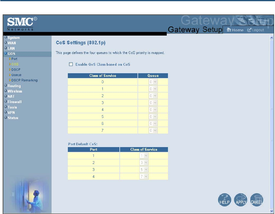
錯誤! 尚未定義樣式。
66
SMCD3GN2 Wireless Cable Modem Gateway Administrator Manual
Figure 32. CoS Settings Menu
To define CoS settings:
1. Check Enable QoS Class based on CoS.
2. For each class of service, assign a queue number from 0 to 3. Higher priority values are
evaluated as being of higher importance than lower priority values.
3. Under Port Default CoS, map the Gateway’s four ports to the classes of service you
defined in the previous step.
y CoS setting from 0 to 3 = normal priority. Packets in this queue leave the port after the
high-priority queue is emptied.
y CoS setting from 4 to 7 = high priority. Packets in this queue leave the port first.
4. Click Apply.
錯誤! 尚未定義樣式。
67
SMCD3GN2 Wireless Cable Modem Gateway Administrator Manual
DSCP Based QoS Menu
The DSCP Based QoS menu lets you classify and prioritize traffic using DSCP tags. DSCP
allows the Gateway to determine how traffic classes should be prioritized. Using the DSCP
Based QoS menu, you can use DSCP to provide different levels of service to conforming
and non-conforming traffic by appropriately selecting the DSCP values in this menu. The
Gateway uses the Hierarchical Token Bucket queuing algorithm, which divides the 64
possible DSCP code values into 8 queues.
Table 11 shows the actual queuing.
Table 11. Queuing for DSCP-Based QoS
Name Precedence DSCP Range Priority
Routing (default) 000 (0) 000000(0) – 000111 (7) 8
Priority 001 (1) 001000 (8) – 001111 (15) 7
Immediate 010 (2) 010000 (16) – 010111 (23) 6
Flash 011 (3) 011000 (24) – 011111 (31) 5
Flash Override 100 (4) 100000 (32) – 100111 (39) 4
Critical 101 (5) 101000 (40) – 101111 (47) 3
Internetwork Control 110 (6) 111000 (48) – 110111 (55) 2
Network Control 111 (7) 111000 (56) – 111111 (63 1
To access the DSCP Based QoS menu, click QOS in the menu bar and then click the DSCP
submenu in the menu bar. Figure 33 shows an example of the menu.
Note: The DSCP submenu is not available in the menu bar if Enable QOS Module
is not checked in the QoS Settings menu (see page 62).
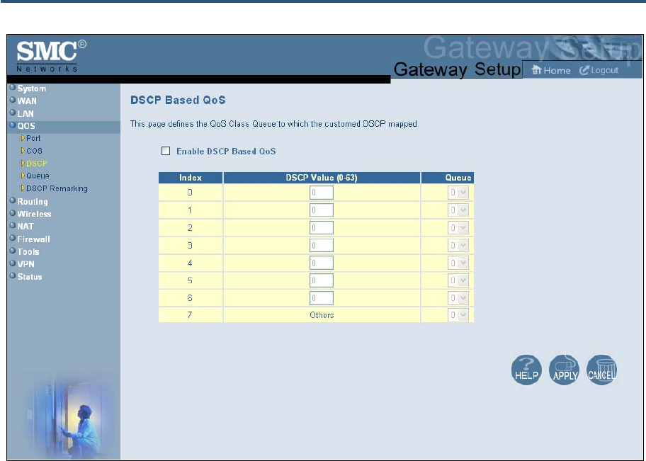
錯誤! 尚未定義樣式。
68
SMCD3GN2 Wireless Cable Modem Gateway Administrator Manual
Figure 33. DSCP Based QoS Menu
To define DSCP-based QoS settings:
1. Check Enable DSCP Based QoS.
2. For each index, select a DSCP value from 0 to 63.
3. Under Queue, select a queue (from 0 to 3) you want to map to this DSCP value. Higher
priority values are evaluated as being of higher importance than lower priority values.
4. To define DSCP-based QoS values for other queues, repeat steps 2 and 3.
5. Click Apply.
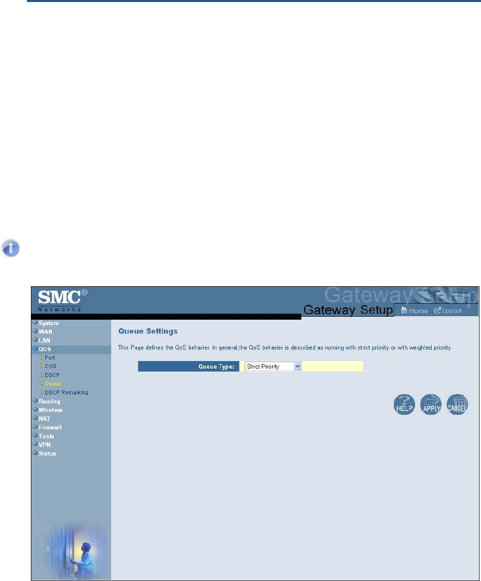
錯誤! 尚未定義樣式。
69
SMCD3GN2 Wireless Cable Modem Gateway Administrator Manual
Queue Settings Menu
The Queue Settings menu lets you configure QoS behavior as either strict priority or
weighted priority.
y Strict priority – allows delay-sensitive data such as voice to be sent before packets in
other queues.
y Weighted priority – lets you assign each queue with a certain weight indicating the
amount of guaranteed capacity, with high priority packets served before any low priority
packets.
To access the Queue Settings menu, click QOS in the menu bar and then click the Queue
submenu in the menu bar. Figure 34 shows an example of the menu.
Note: The Queue submenu is not available in the menu bar if Enable QOS
Module is not checked in the QoS Settings menu (see page 62).
Figure 34. Queue Settings Menu
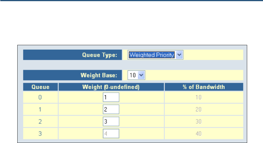
錯誤! 尚未定義樣式。
70
SMCD3GN2 Wireless Cable Modem Gateway Administrator Manual
By default, the Gateway uses strict priority. To change to weighted priority:
1. For Queue Type, select Weighted Priority. The options in Figure 35 appear.
Figure 35. Weighted Priority Options
2. For Weight Base, select a queue weight to ensure that some sets of queues get higher
thresholds than others. Queue weight directs the Gateway to set the queue thresholds
proportionately. Choices are 8 or 10. Queues with a weight of 10 are longer than those with
a queue weight of 8.
3. For each Gateway queue, select a weight. Each weight corresponds to a percentage of
consumed bandwidth, as shown in the % of Bandwidth column.
4. When you finish, click Apply.
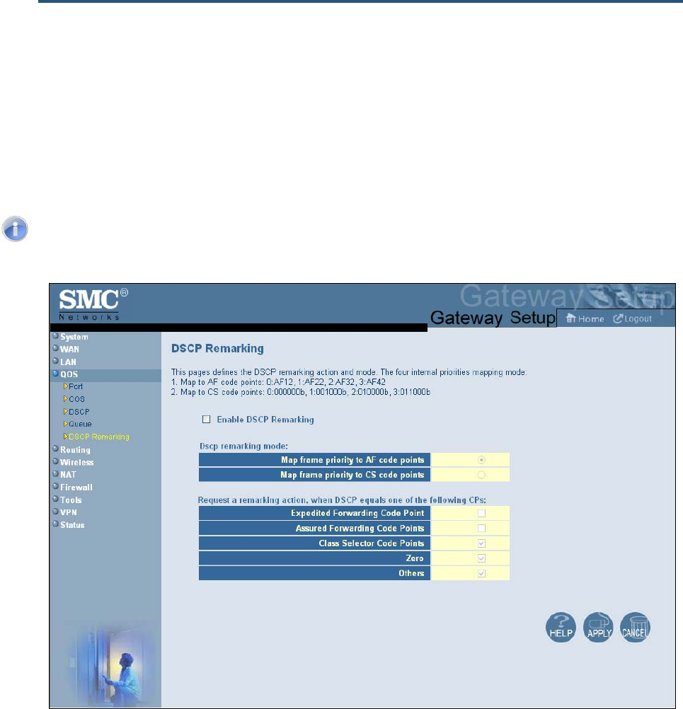
錯誤! 尚未定義樣式。
71
SMCD3GN2 Wireless Cable Modem Gateway Administrator Manual
DSCP Remarking Menu
The DSCP Remarking menu lets you configure the Gateway’s DSCP remarking mode and
actions.
To access the Queue Settings menu, click QOS in the menu bar and then click the DSCP
Remarking submenu in the menu bar. Figure 36 shows an example of the menu.
Note: The DSCP Remarking submenu is not available in the menu bar if Enable
QOS Module is not checked in the QoS Settings menu (see page 62).
Figure 36. DSCP Remarking Menu

錯誤! 尚未定義樣式。
72
SMCD3GN2 Wireless Cable Modem Gateway Administrator Manual
To configure DSCP remarking settings:
1. Check Enable DSCP Remarking.
2. Complete the options in the menu and refer to Table 12.
3. When you finish, click Apply.
Table 12. DSCP Remarking Options
Option Description
Dscp remarking mode Lets you select the DSCP remarking mode that the Gateway is to use. Choices are:
• Map frame priority to AF code points = select this option for Quality of Service configurations that use
assured forwarding (AF) code points to mark packets. AF guarantees a certain amount of bandwidth to
an AF class and allows access to extra bandwidth, if available. (default)
• Map frame priority to CS code points = select this option for Quality of Service configurations that use
class selector (CS) code points to mark packets. CS provides code points that can be used for
backward compatibility with IP Precedence. IP Precedence is a legacy technology that the Gateway
supports for backwards compatibility.
Request a remarking action when DSCP equals one of the following CPs
Expedited Forwarding
Code Point Expedited forwarding provides a low-loss, low-latency, low-jitter, and assured bandwidth service.
Applications such as VoIP, video, and other time sensitive applications require a robust network treatment
like expedited forwarding. When checked, the Gateway requests a remarking action if DSCP equals an
expedited forwarding code point. By default, this option is not checked.
Assured Forwarding
Code Points Assured forwarding defines a method by which packets can be given different forwarding assurances.
Traffic can be divided into different classes and then each class given a certain percentage of bandwidth.
For example, one class could have 50% of the available link bandwidth, another class could have 30%,
and another 20% of the bandwidth. When checked, the Gateway requests a remarking action if DSCP
equals an assured forwarding code point. By default, this option is not checked.
Class Selector Code
Points Class Selector code points are code points that can be used for backward compatibility with IP Precedence
models. When checked, lets the Gateway request a remarking action if DSCP equals a class selector code
point. By default, this option is checked, but does not take effect until the OSPF Status changes to
ENABLE.
Zero When checked, lets the Gateway request a remarking action if DSCP equals zero. By default, this option is
checked, but does not take effect until the OSPF Status changes to ENABLE.
Others When checked, lets the Gateway request a remarking action if DSCP equals a non-zero value. By default,
this option is checked, but does not take effect until the OSPF Status changes to ENABLE.
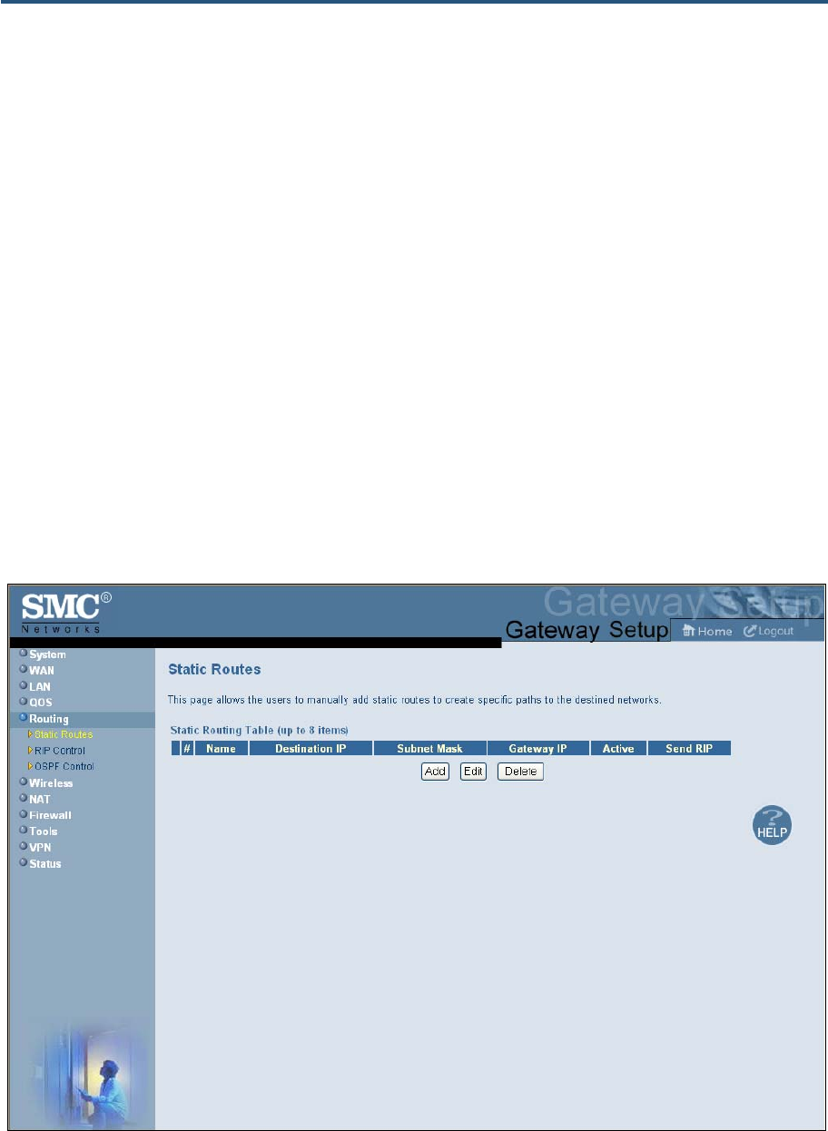
錯誤! 尚未定義樣式。
73
SMCD3GN2 Wireless Cable Modem Gateway Administrator Manual
Routing Menus
The Routing menu provides the following submenus for configuring Gateway routing:
y Static routes – lets you manually add static routes to create specific paths to desired
destinations. See page 73.
y RIP control – lets you select how the Gateway adjusts to physical changes in the
network’s layout and exchange routing tables with other routers. See page 75.
y OSPF control – lets you control how the Gateway works with the OSPF protocol. See
page 79.
Static Routes Menu
A static route is a pre-determined pathway that network information must travel to reach a
specific host or network. Using the Static Routes menu, you can manually add static routes
to create specific paths to desired destinations.
To access the Static Routes menu, click Routing in the menu bar and then click the Static
Routes submenu. Figure 37 shows an example of the menu.
Figure 37. Static Routes Menu
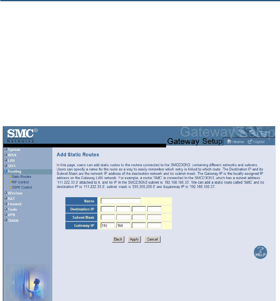
錯誤! 尚未定義樣式。
74
SMCD3GN2 Wireless Cable Modem Gateway Administrator Manual
Using the Static Routes menu, you can add up to eight static routes, containing different
networks and subnets, to routers connected to the Gateway. The following example
describes how to configure a static route For example, assume that a router called SMC is
connected to the Gateway with subnet address 111.222.33.0 attached to it. Also, assume
that the router’s IP address in the Gateway subnet is 192.168.100.33. In this example, you
can add a static route named SMC, with a destination IP address of 111.222.33.0, a subnet
mask of 255.255.255.0, and a gateway IP address of 192.168.100.33.
Adding Static Routes
To add static routes:
1. In the Static Routes menu, click Add. The Add Static Routes menu in Figure 38 appears.
Figure 38 Add Static Routes Menu
2. Complete the fields in the Add Static Routes menu (see Table 18).
3. Click Apply. (Or click Back to return to the Static Routes menu or Cancel to cancel any
selections you made.) If you clicked Apply, the static route is added to the Static Routing
Table.
4. To define additional static routes (up to eight), repeat steps 1 through 3.
5. To change the settings for a static route, click the radio button to the left of the static route
you want to change and click the Edit button. When the Add Static Routes menu appears,
edit the settings as necessary (see Table 18) and click Apply.
錯誤! 尚未定義樣式。
75
SMCD3GN2 Wireless Cable Modem Gateway Administrator Manual
6. To delete a static route, click the radio button to the left of the static route you want to
delete and click the Delete button. No precautionary message appears before you delete a
static route.
Table 13. Add Static Routes Menu Options
Option Description
Name Name used to identify the route.
Destination IP IP address of the destination network.
Subnet Mask Subnet mask of the destination network. The subnet mask determines which part of the Destination
IP address is the network portion and which part is the host portion.
Gateway IP Locally assigned IP address on the Gateway that allows contact between the Gateway and the
remote network or host.
RIP Control Menu
RIP sends routing-update messages at regular intervals. When a router receives a routing
update that includes changes to an entry, it updates its routing table to reflect the new route.
The metric value for the path is increased by 1, and the sender is indicated as the next hop.
RIP routers maintain only the best route (the route with the lowest metric value) to a
destination. After updating its routing table, the router immediately begins transmitting
routing updates to inform other network routers of the change. These updates are sent
independently of the regularly scheduled updates that RIP routers send.
In general, when a router sends a routing update, the following authentication sequence
occurs
1. A router sends a routing update with a key and the corresponding key number to the
neighbor router.
2. The receiving (neighbor) router checks the received key against the same key stored in its
own memory.
3. If the two keys match, the receiving router accepts the routing update packet. If the two
keys do not match, it rejects the routing update packet.
Using the RIP Control menu, you can configure the way how the Gateway adjusts to
physical changes in the network’s layout and exchange routing tables with other routers. To
access the RIP Control menu, click Routing in the menu bar and then click the RIP Control
submenu. Figure 46 shows an example of the menu and Table 21 describes the options.
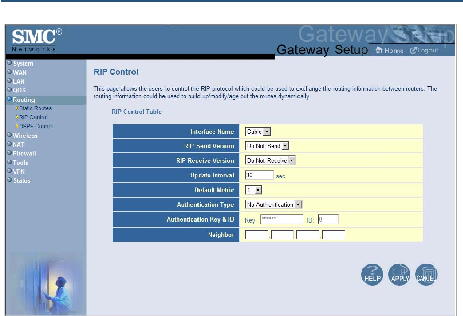
錯誤! 尚未定義樣式。
76
SMCD3GN2 Wireless Cable Modem Gateway Administrator Manual
Figure 39. RIP Control Menu

錯誤! 尚未定義樣式。
77
SMCD3GN2 Wireless Cable Modem Gateway Administrator Manual
Table 14. RIP Control Menu Options
Option Description
WPS Summary
Interface Name Select the name of the interface. Choices are
• Cable (default)
• CPE
RIP Send Version Select the format and the broadcasting method of the RIP packets that the Gateway sends. Choices
are:
• Do Not Send (default)
• RIP1
• RIP2
• RIP1/2
Your selection should match the version supported by other routers on your network.
RIP Receive Version Select the format and the broadcasting method of the RIP packets that the Gateway receives.
Choices are:
• Do Not Receive (default)
• RIP1
• RIP2
• RIP1/2
Your selection should match the version supported by other routers on your network.
Update Interval How often, in seconds, the Gateway sends routing-update messages. Default is 30 seconds.
Default Metric Number by which the metric value for the path increases when the Gateway receives a routing
update that includes changes to an entry. Choices are 1 – 15. Default is 1.
Authentication Type The authentication mechanism used, if any. Choices are:
• No Authentication = no authentication is used. If you keep this default setting, the Authentication
Key & ID fields are gray and unavailable. (default)
• Simple Password = an authentication method where a clear text password is sent to participating
neighbors on the network. This selection sends the authenticating password over the network,
possible making it available to individuals who can access packets off the network. Do not use this
option as part of your security strategy, Rather, use it to avoid accidental changes to the routing
infrastructure. If you select this setting, the first field in the Authentication Key & ID option becomes
available for entering the password.
• MD5 = an authentication method that works much like Simple Password authentication, except
that MD5 does not send the key over the network. Instead, a router uses the MD5 algorithm to
produce a message digest of the key (also called a hash). The router sends the message digest
instead of the key itself, which ensures that no one can eavesdrop on the network and learn keys
during transmission. If you select this setting, the first field in the Authentication Key & ID option
becomes available for entering the key and the second field becomes available for entering the ID.
Authentication Key & ID Specify the appropriate information based on the Authentication Type selected:
• No Authentication – no entry required; fields are gray and unavailable. (default)
• Simple Password = in the first field, enter the clear-text password to be used for authentication.
The second field requires no entry, and is gray and unavailable.
• MD5 = in the first field, enter the MD5-hash password. In the second field, enter the Key Identifier
that identifies the key used to create the authentication data for this message.

錯誤! 尚未定義樣式。
78
SMCD3GN2 Wireless Cable Modem Gateway Administrator Manual
Neighbor Enter the IP address of the Gateway’s RIP neighbor router.
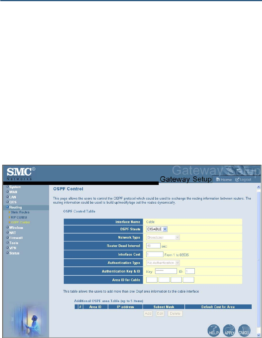
錯誤! 尚未定義樣式。
79
SMCD3GN2 Wireless Cable Modem Gateway Administrator Manual
OSPF Control Menu
OSPF is a router protocol used in larger autonomous system networks in preference to RIP,
an older routing protocol that is installed in many of today's corporate networks. Using OSPF,
a host that obtains a change to a routing table or detects a change in the network
immediately multicasts the information to all other hosts in the network, so that all have the
same routing table information. Unlike RIP, in which the entire routing table is sent, the host
using OSPF sends only the part that has changed. With RIP, the routing table is sent to a
neighbor host at a pre-determined interval. OSPF multicasts the updated information only
when a change has taken place.
Using the OSPF Control menu, you can control how the Gateway uses OSPF. You can also
add more than one OSPF area to the cable interface.
To access the OSPF Control menu, click Routing in the menu bar and then click the OSPF
Control submenu. Figure 40 shows an example of the menu and Table 15 describes the
options.
Figure 40. OSPF Control Menu

錯誤! 尚未定義樣式。
80
SMCD3GN2 Wireless Cable Modem Gateway Administrator Manual
Table 15. OSPF Control Menu Options
Option Description
Interface Name A read-only field that shows the name of the interface.
OSPF Status Enables or disables OSPF.
• ENABLE = OSPF is enabled and the remaining fields on this menu, except Interface Name,
become available.
• DISABLE = OSPF is disabled. (default)
Network Type The type of network on which OSPF will be used if OSPF is enabled. Choices are:
• Broadcast = broadcast network. (default)
• Not Broadcast = not broadcast network.
• Point-to-Multipoint = point-to-multipoint network.
• Point-to-Point = point-to-point network.
Router Dead Interval Interval, in seconds, during which at least one hello packet must be received from a neighbor before
the Gateway declares that a neighbor is down. Default is 40 seconds.
Interface Cost Cost of sending a packet on an OSPF interface. Range is 1 – 65535. Default is 1.
Authentication Type The authentication mechanism used, if any. Choices are:
• No Authentication – no authentication is used. If you keep this default setting, the Authentication
Key & ID fields are gray and unavailable. (default)
• Simple Password = an authentication method where a clear text password is sent to participating
neighbors on the network. This selection sends the authenticating password over the network,
possible making it available to individuals who can access packets off the network. Do not use this
option as part of your security strategy, Rather, use it to avoid accidental changes to the routing
infrastructure. If you select this setting, the first field in the Authentication Key & ID option becomes
available for entering the password.
• MD5 = an authentication method that works much like Simple Password authentication, except
that MD5 does not send the key over the network. Instead, a router uses the MD5 algorithm to
produce a message digest of the key (also called a hash). The router sends the message digest
instead of the key itself, which ensures that no one can eavesdrop on the network and learn keys
during transmission. If you select this setting, the first field in the Authentication Key & ID option
becomes available for entering the key and the second field becomes available for entering the ID.
Authentication Key & ID Specify the appropriate information based on the Authentication Type selected:
• No Authentication – no entry required; fields are gray and unavailable. (default)
• Simple Password = in the first field, enter the clear-text password to be used for authentication.
The second field requires no entry, and is gray and unavailable.
• MD5 = in the first field, enter the MD5-hash password. In the second field, enter the Key Identifier
that identifies the key used to create the authentication data for this message.
Area ID for Cable OSPF supports two-level hierarchical routing by using OSPF areas. This approach allows the routing
table size, memory and CPU demands to be kept to a manageable levels. Each area is identified by
32-bit Area ID. This field allows the Gateway to associate packets to the appropriate OSPF area.

錯誤! 尚未定義樣式。
81
SMCD3GN2 Wireless Cable Modem Gateway Administrator Manual
Adding OSPF Areas to the Cable Interface
To add OSPF areas to the cable interface:
1. In the OSPF Control menu, be sure OSPF Status is set to ENABLE. Otherwise, you will
not be able to add OSPF areas to the cable interface.
2. Click the Add button below the Additional OSPF area Table. The Adding OSPF Area
menu appears (see Figure 41).
3. Complete the fields in the Adding OSPF Area menu (see Table 16).
4. Click Apply. (Or click Back to return to the OSPF Control menu or Cancel to cancel any
selections you made.) If you clicked Apply, the OSPF area is added to the Additional
OSPF area Table.
5. To configure additional OSPF area (up to 5), repeat steps 1 through 4. When you finish,
click Apply in the OSPF Control menu to save your settings.
6. To change the settings for an OSPF area, click the radio button to the left of the OSPF
area you want to change and click the Edit button. When the Adding OSPF Area menu
appears, edit the settings as necessary (see Table 16) and click Apply.
7. To delete a predefined service, click the radio button to the left of the OSPF area you want
to delete and click the Delete button. No precautionary message appears before you
delete an OSPF area.
8. Click Apply on the OSPF Control menu.
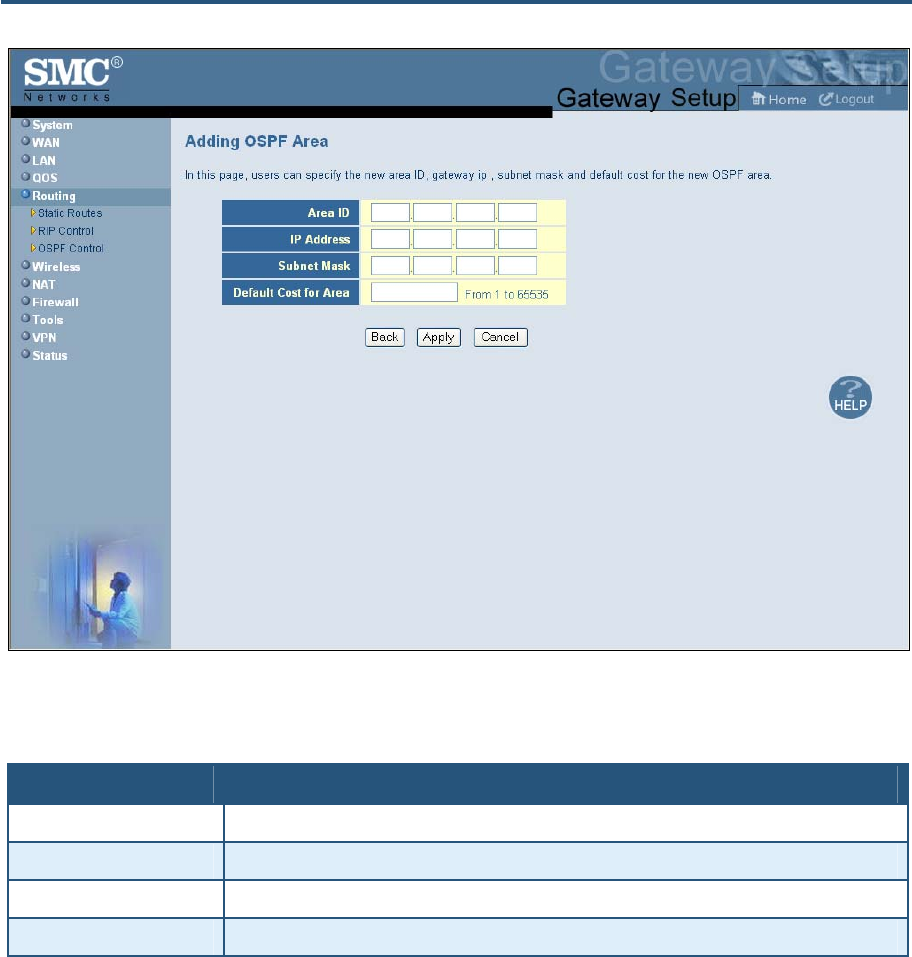
錯誤! 尚未定義樣式。
82
SMCD3GN2 Wireless Cable Modem Gateway Administrator Manual
Figure 41. Adding OSPF Area Menu
Table 16. Adding OSPF Area Menu Options
Option Description
Area ID Area ID associated with the OSPF interface.
IP Address IP address associated with the OSPF interface.
Subnet Mask Subnet mask associated with the OSPF interface.
Default Cost for Area Cost for sending a packet on the OSPF interface.
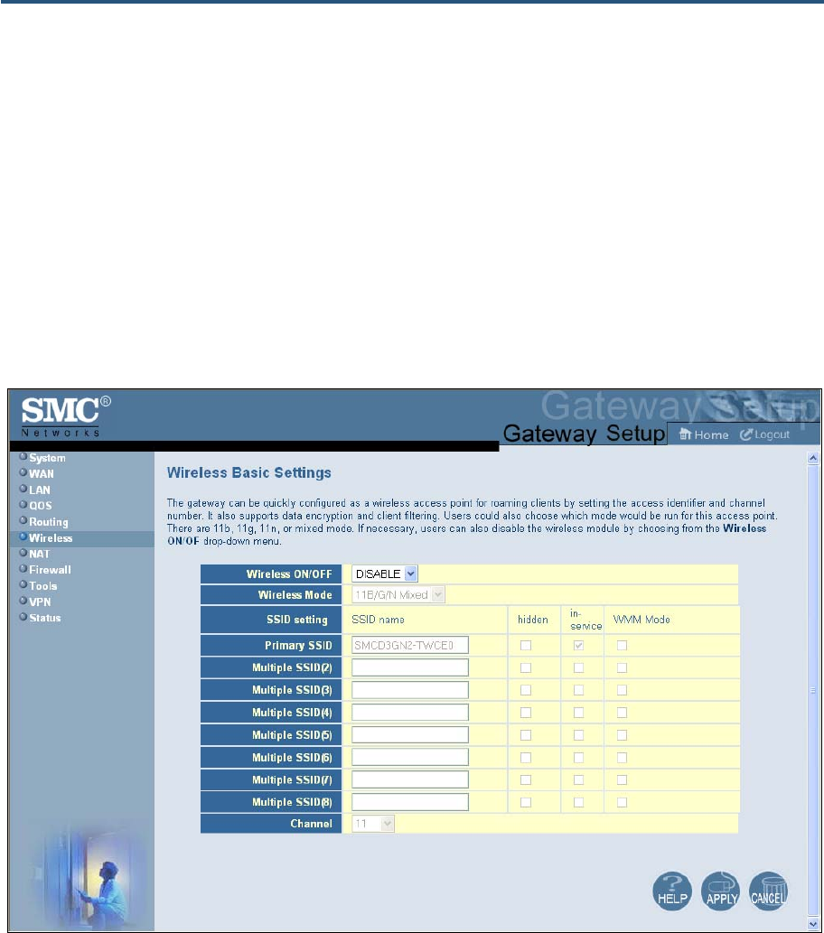
錯誤! 尚未定義樣式。
83
SMCD3GN2 Wireless Cable Modem Gateway Administrator Manual
Wireless Basic Settings Menu
The Wireless Basic Settings menu lets you configure basic wireless settings, such as:
y Enabling or disabling the Gateway’s wireless operation
y Selecting a wireless mode
y Configuring primary and multiple SSIDs
y Configuring channel settings
To access the Wireless Basic Settings menu, click Wireless in the menu bar. Figure 42
shows an example of the menu and Table 17 describes the settings you can select.
Figure 42. Wireless Basic Settings Menu
錯誤! 尚未定義樣式。
84
SMCD3GN2 Wireless Cable Modem Gateway Administrator Manual
Table 17. Wireless Basic Settings Menu Options
Option Description
Wireless ON/OFF Enables or disables the Gateway’s wireless operation.
• ENABLE = Gateway’s wireless operation is active. Selecting this option activates the options in this
menu. Clicking Apply displays the submenus below the Wireless menu.
• DISABLE = Gateway’s wireless operation is not active. Selecting this option deactivates the options in
this menu. Clicking Apply hides the submenus below the Wireless menu. (default)
Wireless Mode If wireless operation is enabled for the Gateway, this option selects the wireless mode used by the
Gateway. Choices are:
• 11B/G Mixed = use this setting if you have a combination of IEEE 802.11b and IEEE 802.11g devices
on your network.
• 11B Only = use this setting if you have only IEEE 802.11b devices on your network or want to limit your
network to IEEE 802.11b devices.
• 11G Only = use this setting if you have only IEEE 802.11g devices on your network or want to limit your
network to IEEE 802.11g devices.
• 11N Only = use this setting if you have only IEEE 802.11n devices on your network or want to limit your
network to IEEE 802.11n devices.
• 11G/N Mixed = use this setting if you have a combination of IEEE 802.11g and IEEE 802.11n devices
on your network.
• 11B/G/N Mixed = use this setting if you have a combination of IEEE 802.11b, IEEE 802.11g, and IEEE
802.11n devices on your network. (default)
Primary/Multiple SSID
settings SSID is the network name shared among all devices in a wireless network. The SSID must be identical for
all devices in the wireless network. It is case-sensitive and must not exceed 32 alpha-numeric characters,
which may be any keyboard character. Be sure these settings are the same for all devices in your wireless
network. You can set up a primary SSID and seven additional SSIDs, designated Multiple SSID(2) through
Multiple SSID(8). Each SSID can be hidden or configured for Wi-Fi Multimedia (WMM) mode. Each SSID,
except the primary SSID, can also be configured to be in or out of service.
• Hidden = when checked, hides the SSID. Use this setting to block illegal connections. Users cannot
reconnect automatically or manually to a wireless network that uses a hidden SSID. The wireless
network that uses a hidden SSID does not appear in the Microsoft Windows Wireless Network
Connection window.
• In-service = when checked, broadcasts the Gateway’s SSID.
• WMM Mode = when checked, enables WMM. Enabling WMM can help control latency and jitter when
transmitting multimedia content over a wireless connection.
Channel Select the appropriate channel from the list provided to correspond with your network settings, between 1
and 11 (in North America). Default is Auto, which selects the appropriate channel automatically. All devices
in your wireless network must use the same channel to work properly.
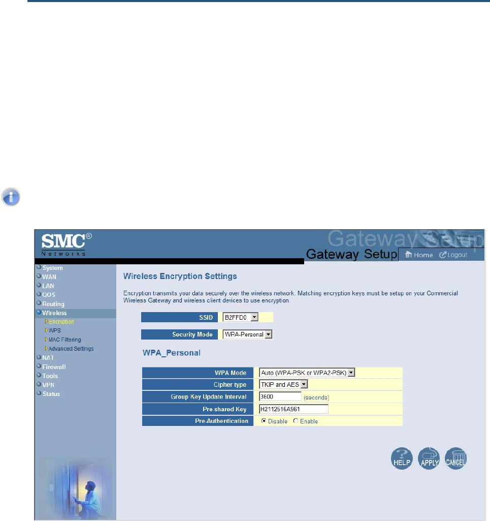
錯誤! 尚未定義樣式。
85
SMCD3GN2 Wireless Cable Modem Gateway Administrator Manual
Wireless Encryption Settings Menu
Using the Wireless Encryption Settings menu, you can protect the data transmitted across
your wireless network. The same encryption keys you specify here must also be configured
on your other wireless client devices on your wireless network.
To access the Wireless Encryption Settings menu, click Wireless in the menu bar and then
click the Encryption submenu. Figure 43 shows an example of the menu and Table 18
describes the settings you can select.
Note: The Encryption submenu is not available in the menu bar if wireless
operation is disabled in the Wireless Basic Settings menu (see page 83).
Figure 43. Wireless Encryption Settings Menu
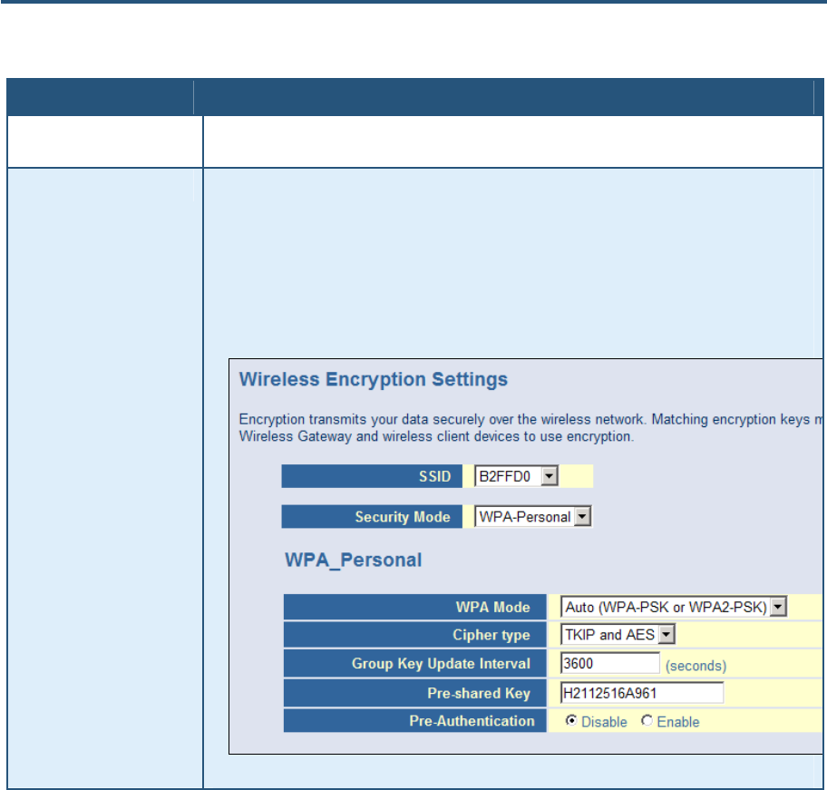
錯誤! 尚未定義樣式。
86
SMCD3GN2 Wireless Cable Modem Gateway Administrator Manual
Table 18. Wireless Encryption Settings Menu Options
Option Description
SSID Network name of the primary wireless carrier. This field can be changed by administrators, but not by
users.
Security Mode Selects the security mode used to protect transmissions across the wireless network.
• None = no security is used over the wireless network.
• WEP = Wired Equivalency Privacy encryption is used over the wireless network. Select this option
if your wireless adapters support WEP but not WPA-Personal. WEP provides basic security, but is
not as secure as WPA-Personal. If you select WEP, select the options in Figure 44 and Table 19.
• WPA-Personal = select this option if your wireless adapters support WPA-Personal. This
encryption method is superior to WEP and offers two cipher types, TKIP and AES, with dynamic
encryption keys. If you select WPA-Personal, select the options in
• Figure 45 and Table 20. (default)
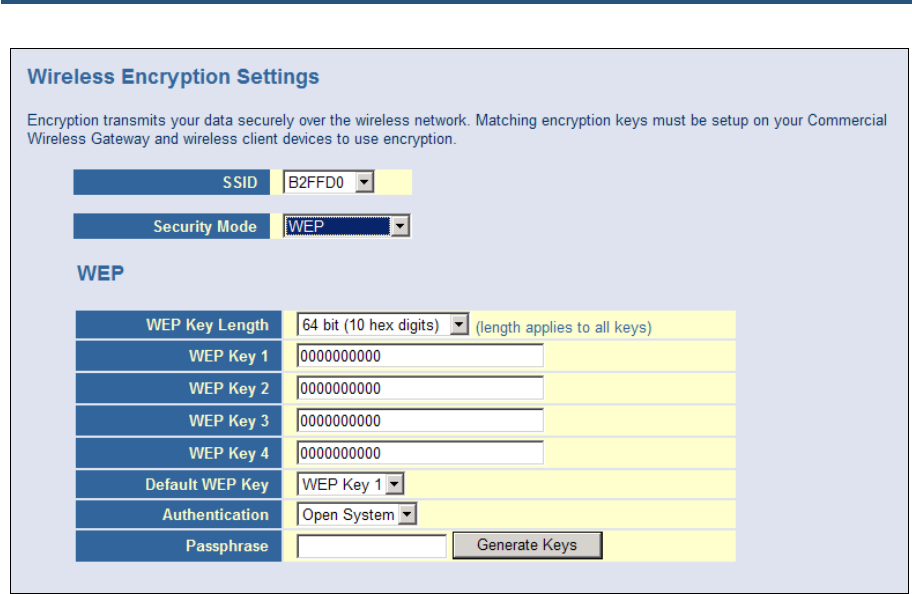
錯誤! 尚未定義樣式。
87
SMCD3GN2 Wireless Cable Modem Gateway Administrator Manual
Figure 44. WEP Options
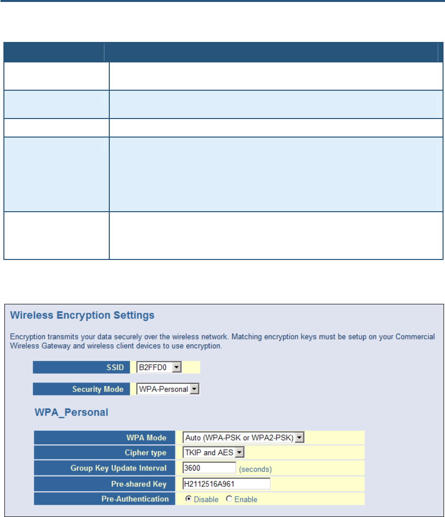
錯誤! 尚未定義樣式。
88
SMCD3GN2 Wireless Cable Modem Gateway Administrator Manual
Table 19. WEP Options
Option Description
WEP Key Length Level of WEP encryption applied to all WEP keys. Choices are 64-bit (10 hex digits) and 128-bit (26
hex digits).
WEP Key 1 – WEP Key 4 Fields for entering up to four WEP keys manually. Alternatively, you can click the Generate Keys
button to generate these keys automatically.
Default WEP Key Specifies which of the four WEP keys the Gateway is to use as its default.
Authentication Authentication used. Choices are:
• Open System = clients can only associate to the wireless access point using Open Option.
(default)
• Shared Key = all wireless stations share the same secret key.
• Automatic = clients can associate to the wireless access point using Open System or Shared Key.
Passphrase A sequence of words or text that can be used to automatically generate WEP keys. A passphrase
can consist of from 8 to 63 ASCII characters. You can use upper-case, lower-case, and numeric
characters to from your passphrase. A Generate Keys button next to this field lets the Gateway
generate a passphrase based on the characters typed in this field.
Figure 45. WPA_Personal Options
錯誤! 尚未定義樣式。
89
SMCD3GN2 Wireless Cable Modem Gateway Administrator Manual
Table 20. WPA_Personal Options
Option Description
WPA Mode Lets administrators select the WPA mode they want to use. Choices are:
• WPA-PSK = select this setting if your access points and wireless clients support WPA-Pre-Shared
Key (PSK) Authentication.
• WPA2-PSK = select this setting if your access points and wireless clients support WPA2-PSK
Authentication.
• Auto (WPA-PSK or PWA2-PSK) = select this setting if your access points and wireless clients
support either WPA-PSK or WPA2-PSK. (default)
Cipher type Algorithm encryption to be used. Choices are:
• TKIP = automatic encryption with WPA-PSK; requires pre-shared key.
• AES = automatic encryption with WPA2-PSK; requires pre-shared key.
• TKIP and AES = uses both TKIP and AES cipher types; requires pre-shared key. (default)
Group Key Update Interval Number of seconds that instructs the Gateway how often it should change the encryption keys.
Usually the security level is higher if you set the period shorter to change encryption keys more often.
Default value is 3600 seconds (6 minutes). Type 0 to disable group key update interval.
Pre-shared Key Shared secret between the Gateway and access points and wireless clients. Please check whether a
default pre-shared key is required.
Pre-Authentication Enables secure fast roaming, without noticeable signal latency. By default, this option is disabled.
WPS Setup
Using the WPS Setup menu, you can enable or disable WPS. WPS is a standard for easy
and secure wireless network set up and connections.
The advantages of WPS are:
y WPS automatically configures the network name (SSID) and WPA security key for the
Gateway and for the access point and wireless devices that join the network.
y You do not need to know the network name and security keys or passphrases to use
WPS to join a wireless network.
y No one can guess your security keys or passphrase because they are generated
randomly.
y WPS uses the Extensible Authentication Protocol (EAP), which is a strong authentication
protocol used in WPA2.
The disadvantages of WPS are:
y Unless all the Wi-Fi devices on the network are WPS-compatible, you cannot take
advantage of the ease of securing the network.
y Not all wireless equipment supports WPS.
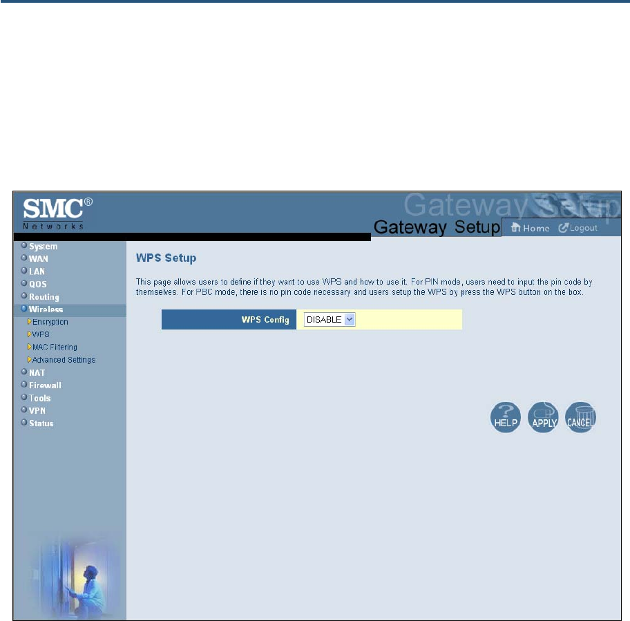
錯誤! 尚未定義樣式。
90
SMCD3GN2 Wireless Cable Modem Gateway Administrator Manual
y If your wireless devices do not support WPS, it can be hard to join a network that was
set up with WPS because the wireless network name and security key are random
sequences of letters and numbers.
To access the WPS Setup menu, click Wireless in the menu bar and then click the WPS
submenu. Figure 46 shows an example of the menu. Using the WPS Config drop-down list,
select the appropriate option to enable or disable WPS setup.
Figure 46. WPS Setup Menu
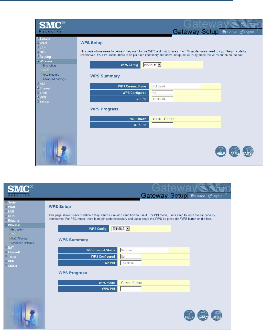
錯誤! 尚未定義樣式。
91
SMCD3GN2 Wireless Cable Modem Gateway Administrator Manual
By default, WPS is disabled. If you select ENABLE and click Apply, the options in
Figure 47 are displayed. Table 21 describes the options shown.
Figure 47. WPS Setup Menu with WPS Config Enabled
錯誤! 尚未定義樣式。
92
SMCD3GN2 Wireless Cable Modem Gateway Administrator Manual
Table 21. WPS Summary and WPS Progress Options
Option Description
WPS Config Enables or disables the Gateway’s WPS setup.
• ENABLE = Gateway’s WPS setup is available. (default)
• DISABLE = Gateway’s WPS setup is unavailable.
WPS Summary
WPS Current Status A read-only field that shows whether WPS is currently being used.
WPS Configured A read-only field that whether WPS has been configured.
AP PIN A read-only field that shows the personal identification number (PIN) for the access point.
WPS Progress
WPS mode Determines whether WPS can be configured using a PIN or the WPS button on the front panel of the
Gateway.
• PIN = requires users to enter a PIN in the WPS Setup menu to configure WPS.
• PBC = Push Button Configuration. Allows users to use the WPS button on the front panel of the
Gateway to configure WPS.
WPS PIN If PIN was selected for WPS mode, enter the PIN that users must enter to enable WPS. The PIN
must be 8 alpha-numeric characters long.
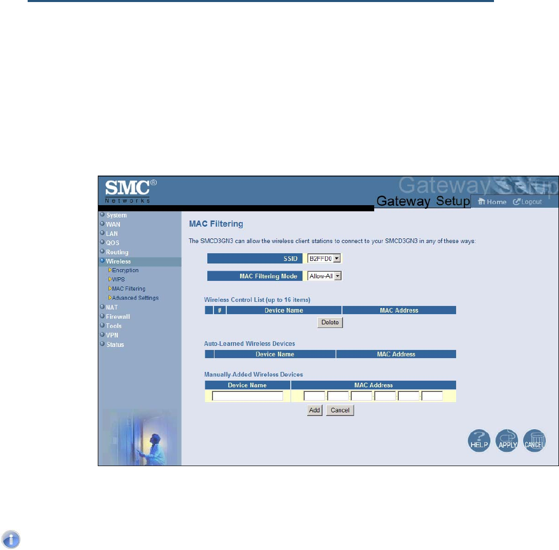
錯誤! 尚未定義樣式。
93
SMCD3GN2 Wireless Cable Modem Gateway Administrator Manual
MAC Filtering
The MAC Filtering menu allows wireless client stations to connect over a wireless
connection in two ways:
y By allowing all wireless station access.
y By allowing only trusted PCs.
To access the MAC Filtering menu, click Wireless in the menu bar and then click the
MAC Filtering submenu.
Figure 48 shows an example of the menu and Table 22 describes the settings you can
select.
Note: The MAC Filtering submenu is not available in the menu bar if wireless
operation is disabled in the Wireless Basic Settings menu (see page 83).
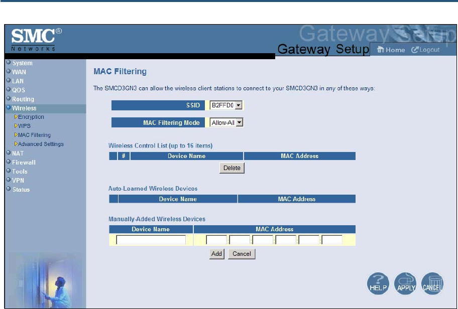
錯誤! 尚未定義樣式。
94
SMCD3GN2 Wireless Cable Modem Gateway Administrator Manual
Figure 48. MAC Filtering Menu
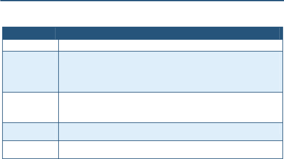
錯誤! 尚未定義樣式。
95
SMCD3GN2 Wireless Cable Modem Gateway Administrator Manual
Table 22. MAC Filtering Options
Option Description
SSID Network name of the primary wireless carrier.
MAC Filtering Mode Determines which wireless client stations can connect to the Gateway. The choices are:
• Allow- All = all wireless client stations can connect to the Gateway. (default)
• Allow = allow only the wireless client stations in the MAC filter table to connect to the Gateway.
• Deny = no wireless client stations can connect to the Gateway.
Wireless Control List Shows the device name and MAC address of up to 16 devices that you manually added to the MAC filter
table. To delete a device, click the radio button to the left of the device you want to delete and click the
Delete button. A precautionary message does not appear before deleting the MAC address, so be sure
you do not need the MAC address before deleting it.
Auto-Learned Wireless
Devices Shows the wireless devices whose presence the Gateway has automatically learned.
Manually-Added
Wireless Devices Enter a unique name and MAC address of the wireless devices that you want to manually add to the
Wireless Control List (MAC filter table). Click Add to add the device to the Wireless Control List.
Adding and Deleting Wireless Client Stations
To allow wireless client stations to access the Internet through the Gateway, use the
following procedure to define up to 16 wireless client stations.
1. To add wireless client stations that the Gateway automatically learned on the network,
perform the following steps under Auto-Learned Lan Devices:
a. Click a wireless client station that the Gateway learned automatically.
b. Click Add. The wireless client station is added to the Wireless Control List.
c. To add more auto-learned wireless client stations (up to 16), repeat steps 1a and 1b.
2. To manually add wireless client stations, perform the following steps under Manually-
Added Wireless Devices:
a. Under Device Name, enter a unique name for the device (that is, a name that does not
already appear in the Wireless Control List).
b. Under MAC Address, enter the MAC address of the device.
c. Click Add to add the wireless client station to the Wireless Control List.
d. To manually add more wireless client stations (up to 16), repeat steps 2a through 2c.
3. To delete wireless client stations from the Wireless Control List, click the radio button
corresponding to the wireless client station you want to delete and click the Delete button.
A precautionary message does not appear before deleting a wireless client station.
4. When you finish, click Apply.
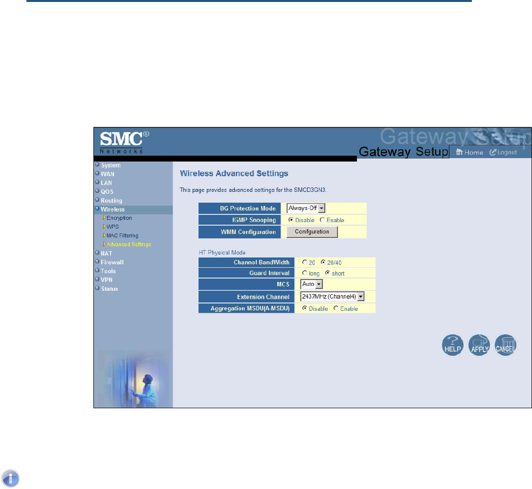
錯誤! 尚未定義樣式。
96
SMCD3GN2 Wireless Cable Modem Gateway Administrator Manual
Advanced Wireless Settings Menu
Using the Advanced Wireless Settings Filtering menu, you can configure advanced wireless
settings for the Gateway.
To access the Advanced Wireless Settings menu, click Wireless in the menu bar and
then click the Advanced Wireless Settings submenu.
Figure 49 shows an example of the menu and Table 23 describes the settings you can
select.
Note: The Advanced Wireless Settings submenu is not available in the menu bar
if wireless operation is disabled in the Wireless Basic Settings menu (see page 83).
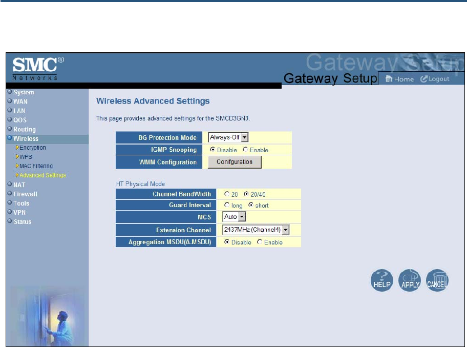
錯誤! 尚未定義樣式。
97
SMCD3GN2 Wireless Cable Modem Gateway Administrator Manual
Figure 49. Wireless Advanced Settings Menu

錯誤! 尚未定義樣式。
98
SMCD3GN2 Wireless Cable Modem Gateway Administrator Manual
Table 23. Wireless Advanced Settings Options
Option Description
BG Protection Mode This mode is a protection mechanism that prevents collisions among 802.11b/g modes. Choices are:
• Auto = BG protection mode goes on or off automatically as needed.
• Always-On = BG protection mode is always on.
• Always-Off = BG protection mode is always off. (default)
IGMP Snooping Enables or disables the Gateway from forwarding multicast traffic intelligently.
• Enable = Gateway listens to IGMP membership reports, queries, and leave messages to identify the
Gateway ports that are members of multicast groups. Multicast traffic will only be forwarded to ports
identified as members of the specific multicast group or groups.
• Disable = Gateway does not analyze all IGMP packets. (default)
WMM Configuration Displays a screen for selecting WMM settings for your wireless access point(s).
HT Physical Mode
Operating Mode Lets you select between Mixed Mode and Green Field.
• Mixed Mode = provides backward compatibility with IEEE 802.11n/a/g/b devices. (default)
• Green Field = used for pure network of 802.11n access points and clients, taking full advantage of the
high-throughput capabilities of the 11n MIMO architecture
Channel BandWidth Select a channel bandwidth of 20 or 20/40.
• 20 = allows only single-channel operation (e.g., 20 MHz).
• 20/40 = allows both single channel operation (20 MHz) and the wider bandwidth operation (40 MHz) by
using two or more adjacent (contiguous channels). A 20/40 BSS is a wireless network that allows a
wider bandwidth operation mode. (default)
Guard Interval The guard interval is the period in nanoseconds that the Gateway listens between packets. Choices are:
• Long = 800 ns guard interval.
• Short = 400 ns guard interval (default)
MCS Modulation Coding Scheme (MCS) is a specification of PHY parameters consisting of modulation order
(BPSK, QPSK, 16-QAM, 64-QAM) and FEC code rate (1/2, 2/3, 3/4, 5/6). MCS is used in the Gateway to
define 32 symmetrical settings. MCS provides for potentially greater throughput. High throughput data
rates are a function of MCS, bandwidth, and guard interval. Default is auto.
Extension Channel Defines a second 20-MHz channel. 40-MHz stations can use this channel in addition to using the control
channel simultaneously.
Aggregation
MSDU(A_MSDU) Enables or disables aggregation of multiple MSDUs in one MPDU. Default is disable.
錯誤! 尚未定義樣式。
99
SMCD3GN2 Wireless Cable Modem Gateway Administrator Manual
NAT Settings
Using the NAT Settings menu, you can enable the Gateway’s Network Address Translation
(NAT) table and allow multiple users at your local site to access the Internet. To access the
NAT Settings menu, click NAT in the menu bar. Figure 50 shows an example of the menu.
By default, the Gateway’s NAT module is enabled. To disable it, uncheck Enable NAT
Module and click Apply. To enable it, check Enable NAT Module and click Apply.
If you enable the Gateway’s NAT module, the following submenus appear under NAT in the
menu bar:
y Port Forwarding - lets you configure the Gateway to provide port-forwarding services
that let Internet users access predefined services. See page 96.
y 1-to-1 Mapping - lets you use the NAT to perform 1-to-1 mapping between global IP
addresses on the cable modem WAN interface and the private IP address on the LAN.
See page 102.
Note: If you change this setting, the Gateway reboots automatically.
Figure 50. NAT Settings Menu
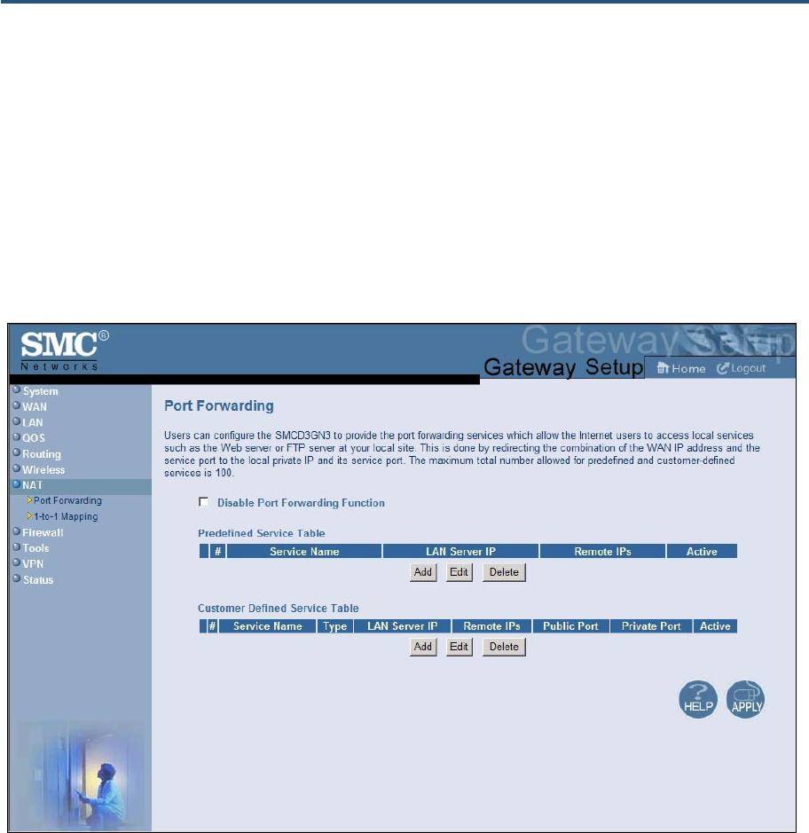
錯誤! 尚未定義樣式。
100
SMCD3GN2 Wireless Cable Modem Gateway Administrator Manual
Port Forwarding Menu
The Port Forwarding menu lets you configure the Gateway to provide port-forwarding
services that let Internet users access predefined services such as HTTP (80), FTP (20/21),
and AIM/ICQ (5190) as well as custom-defined services. You perform port forwarding by
redirecting the WAN IP address and the service port to the local IP address and service port.
You can configure a maximum of 100 predefined and custom-defined services.
To access the Port Forwarding menu, click NAT in the menu bar and then click the Port
Forwarding submenu in the menu bar. Figure 51 shows an example of the menu.
Figure 51. Port Forwarding Menu

錯誤! 尚未定義樣式。
101
SMCD3GN2 Wireless Cable Modem Gateway Administrator Manual
Adding Predefined Services
Using the following procedure, you can select well-known services and specify the LAN host
IP address(es) that will provide the service to the Internet.
1. In the Port Forwarding menu, be sure Disable Port Forwarding Function is not checked
(unchecked is the default setting).
2. Click the Add button below the Predefined Service Table. The Predefined Service menu
appears (see Figure 52).
3. Complete the fields in the Predefined Service menu (see Table 24).
4. Click Apply. (Or click Back to return to the Port Forwarding menu or Cancel to cancel any
selections you made.) If you clicked Apply, the predefined service is added to the
Predefined Service Table.
5. To configure additional predefined services (up to 100, including customer-defined
services), repeat steps 1 through 3.
6. To change the settings for a predefined service, click the radio button to the left of the
service you want to change and click the Edit button. When the Predefined Service menu
appears, edit the settings as necessary (see Table 24) and click Apply.
7. To delete a predefined service, click the radio button to the left of the service you want to
delete and click the Delete button. No precautionary message appears before you delete a
predefined service.
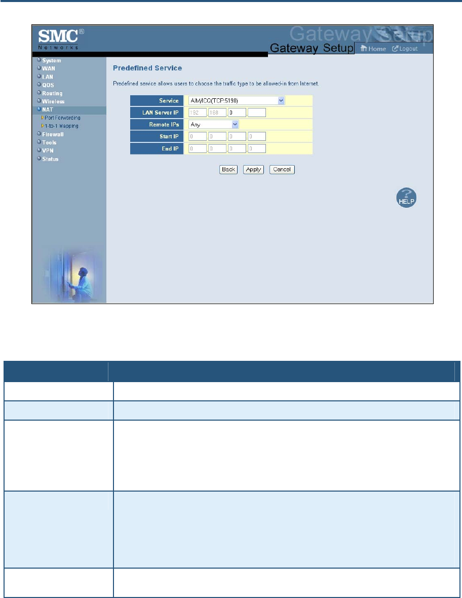
錯誤! 尚未定義樣式。
102
SMCD3GN2 Wireless Cable Modem Gateway Administrator Manual
Figure 52. Predefined Service Menu
Table 24. Predefined Service Menu Options
Option Description
Service List of predefined services from which you can choose.
LAN Server IP IP address of the LAN PC or server that is running the service.
Remote IPs Forwards the service to any remote IP address, one remote IP address, or a range of remote IP
addresses.
• If you select one remote IP address, enter the IP address in the Start IP field.
• If you select a range of remote IP addresses, enter the starting IP address in the Start IP field and
the ending IP address in the End IP field.
Start IP To forward to:
• A single remote IP address, enter the remote IP address.
• A range of remote IP addresses, enter the starting IP address here and the ending IP address
range in the next field.
This field is unavailable if the Gateway is configured for any remote IP addresses.
End IP Enter the ending IP address in the remote IP address range. This field is unavailable if the Gateway
is configured for any remote IP addresses or for a single remote IP address.

錯誤! 尚未定義樣式。
103
SMCD3GN2 Wireless Cable Modem Gateway Administrator Manual
Adding Customer-Defined Services
Using the following procedure, you can define special application services you want to
provide to the Internet. The following example shows how to set port forwarding for a Web
server on an Internet connection, where port 80 is blocked from the WAN side, but port 8000
is available.
Name: Web Server
Type: TCP
LAN Server IP: 192.168.0.100
Remote IPs: Any (allow access to any public IP)
Public Port: 8000
Private Port: 80
With this configuration, all HTTP (Web) TCP traffic on port 8000 from any IP address on the
WAN side is redirected through the firewall to the Internal Server with the IP address
192.168.0.100 on port 80.
To create your own customized services:
1. In the Port Forwarding menu, be sure Disable Port Forwarding Function is not checked
(unchecked is the default setting).
2. Click the Add button below the Customer Defined Service Table. The Customer Defined
Service menu appears (see Figure 53).
3. Complete the fields in the Customer Defined Service menu (see Table 25).
4. Click Apply. (Or click Back to return to the Port Forwarding menu or Cancel to cancel any
selections you made.) If you clicked Apply, the customer-defined service is added to the
Customer Defined Service Table.
5. To configure additional customer-defined services (up to 100, including predefined
services), repeat steps 1 through 3.
6. To change the settings for a customer-defined service, click the radio button to the left of
the service you want to change and click the Edit button. When the Customer Defined
Service menu appears, edit the settings as necessary (see Table 25) and click Apply.
7. To delete a customer-defined service, click the radio button to the left of the service you
want to delete and click the Delete button. No precautionary message appears before you
delete a customized service.
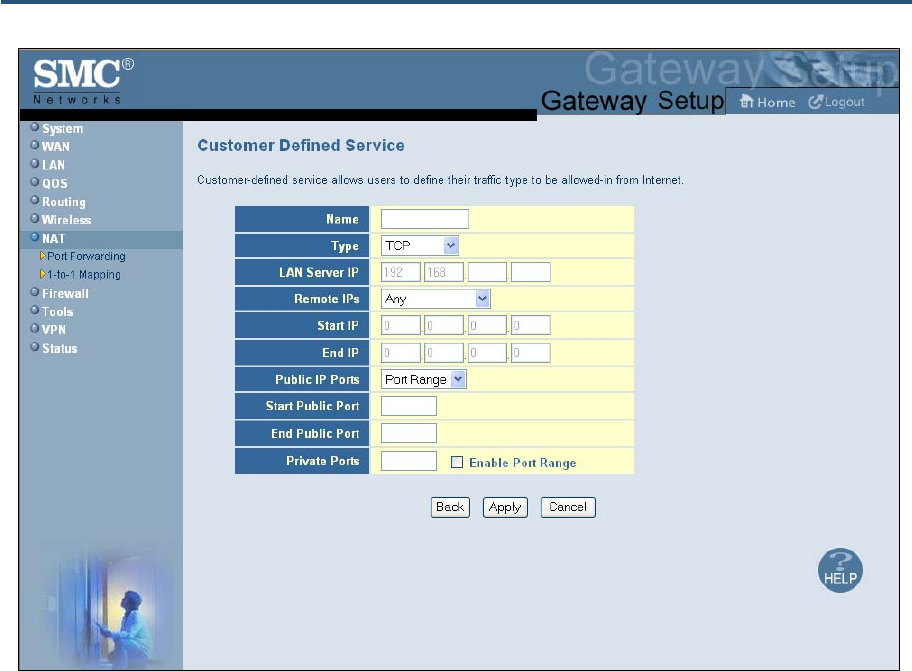
錯誤! 尚未定義樣式。
104
SMCD3GN2 Wireless Cable Modem Gateway Administrator Manual
Figure 53. Customer Defined Service Menu
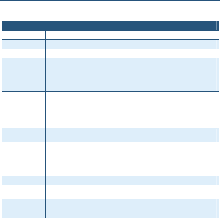
錯誤! 尚未定義樣式。
105
SMCD3GN2 Wireless Cable Modem Gateway Administrator Manual
Table 25. Customer Defined Service Page Options
Option Description
Name Name for identifying the custom service. The name is for reference purposes only.
Type The type of protocol. Choices are TCP, UDP, and TCP/UDP. Default is TCP.
LAN Server IP IP address of the LAN PC or server that is running the service.
Remote IPs Forwards the service to any remote IP address, one remote IP address, or a range of remote IP
addresses.
• If you select one remote IP address, enter the IP address in the Start IP field.
• If you select a range of remote IP addresses, enter the starting IP address in the Start IP field and the
ending IP address in the End IP field.
Start IP To specify:
• A single remote IP address, enter the remote IP address.
• A range of remote IP addresses, enter the starting IP address here and the ending IP address range in
the next field.
This field is unavailable if the Gateway is configured for any remote IP addresses.
End IP Ending IP address in the remote IP address range. This field is unavailable if the Gateway is configured for
any remote IP addresses or a single remote IP address.
Public IP Ports A single public IP port or a range of public IP ports on which the service is provided. If necessary, contact
the application vendor for this information.
• If you select a single public port, enter the port number in the Start Public Port field.
• If you select a range of public ports, enter the starting port number in the Start Public Port field and the
ending port number in the End Public Port field.
Start Public Port Starting number of the port on which the service is provided.
End Public Port Ending number of the port on which the service is provided. This field is unavailable if the Gateway is
configured for a single public IP port.
Private Ports Numbers of the ports whose traffic the Gateway forwards to the LAN. If there is a range of ports, enter the
starting private port here and check Enable Port Range. The Gateway automatically calculates the end
private port. The LAN PC server listens for traffic/data on this port (or these ports).
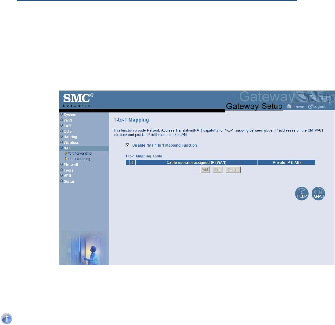
錯誤! 尚未定義樣式。
106
SMCD3GN2 Wireless Cable Modem Gateway Administrator Manual
1-to-1 Mapping Menu
Using the 1-to-1 Mapping menu, you can use the NAT to perform 1-to-1 mapping between
global IP addresses on the cable modem WAN interface and the private IP address on the
LAN.
To access the 1-to-1 Mapping menu, click NAT in the menu bar and then click the 1-to-
1 Mapping submenu.
Figure 54 shows an example of the menu. By default, 1-to-1 mapping is disabled. To enable
it, uncheck Disable NAT 1-to-1 Mapping Function and click Apply. To disable it, check
Disable NAT 1-to-1 Mapping Function and click Apply.
Note: The 1-to-1 Mapping submenu is not available in the menu bar if Enable
NAT Module is not checked in the NAT Settings menu (see page 91).
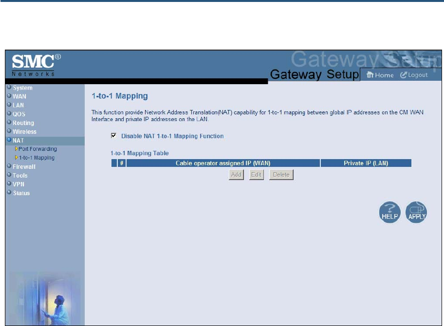
錯誤! 尚未定義樣式。
107
SMCD3GN2 Wireless Cable Modem Gateway Administrator Manual
Figure 54. 1-to-1 Mapping Menu
If you enable (uncheck) NAT 1-to-1 mapping, use the following procedure to define the
mapping between global IP addresses on the cable modem WAN interface and the private
IP address on the LAN.
1. In the 1-to-1 Mapping menu, uncheck Disable NAT 1-to-1 Mapping Function if it is
selected.
2. Click the Add button below 1-to-1 Mapping Table. The Adding NAT 1-to-1 Mapping Entry
menu appears (see Figure 55).
3. Complete the fields in the Predefined Service menu (see Table 26).
4. Click Apply. (Or click Back to return to the 1-to-1 Mapping menu or click Cancel to cancel
any selections you made.) If you clicked Apply, the mapping is added to the 1-to-1
Mapping Table.
5. To configure additional mappings, repeat steps 1 through 3. When you finish, click Apply
in the 1-to-1 Mapping menu to save your settings.
6. To change the settings for a mapping, click the radio button to the left of the mapping you
want to change and click the Edit button. When the Adding NAT 1-to-1 Mapping Entry
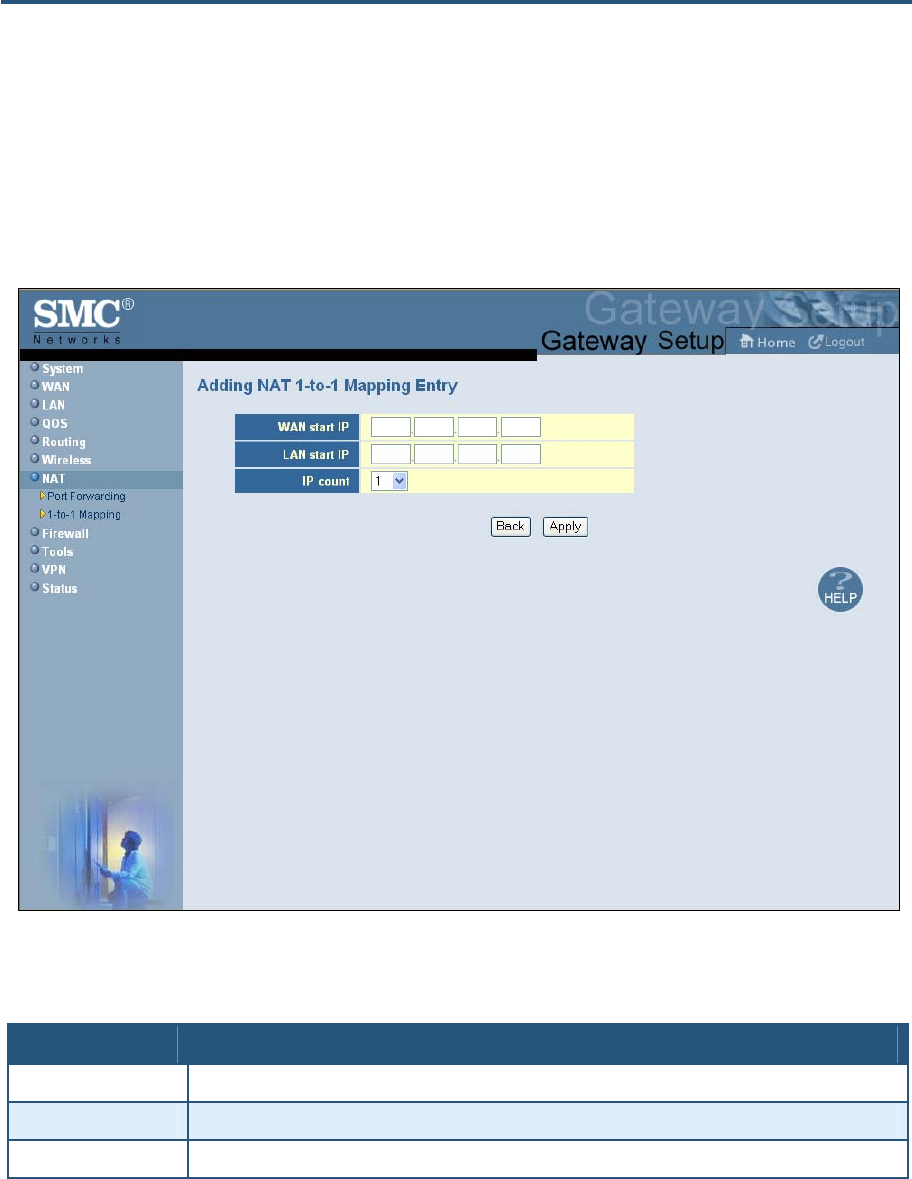
錯誤! 尚未定義樣式。
108
SMCD3GN2 Wireless Cable Modem Gateway Administrator Manual
menu appears, edit the settings as necessary (see Table 26) and click Apply. Click Apply
in the 1-to-1 Mapping menu to save your settings.
7. To delete a mapping, click the radio button to the left of the mapping you want to delete
and click the Delete button. No precautionary message appears before you delete a
mapping.
8. Click Apply in the 1-to-1 Mapping menu to save your settings.
Figure 55. Adding NAT 1-to-1 Mapping Entry
Table 26. Adding NAT 1-to-1 Mapping Entry Options
Option Description
WAN start IP Staring range of the IIP addresses on the WAN that are to be mapped.
LAN start IP Staring range of the IIP addresses on the LAN that are to be mapped.
IP count Count of the IP addresses to be mapped. Default is 1.
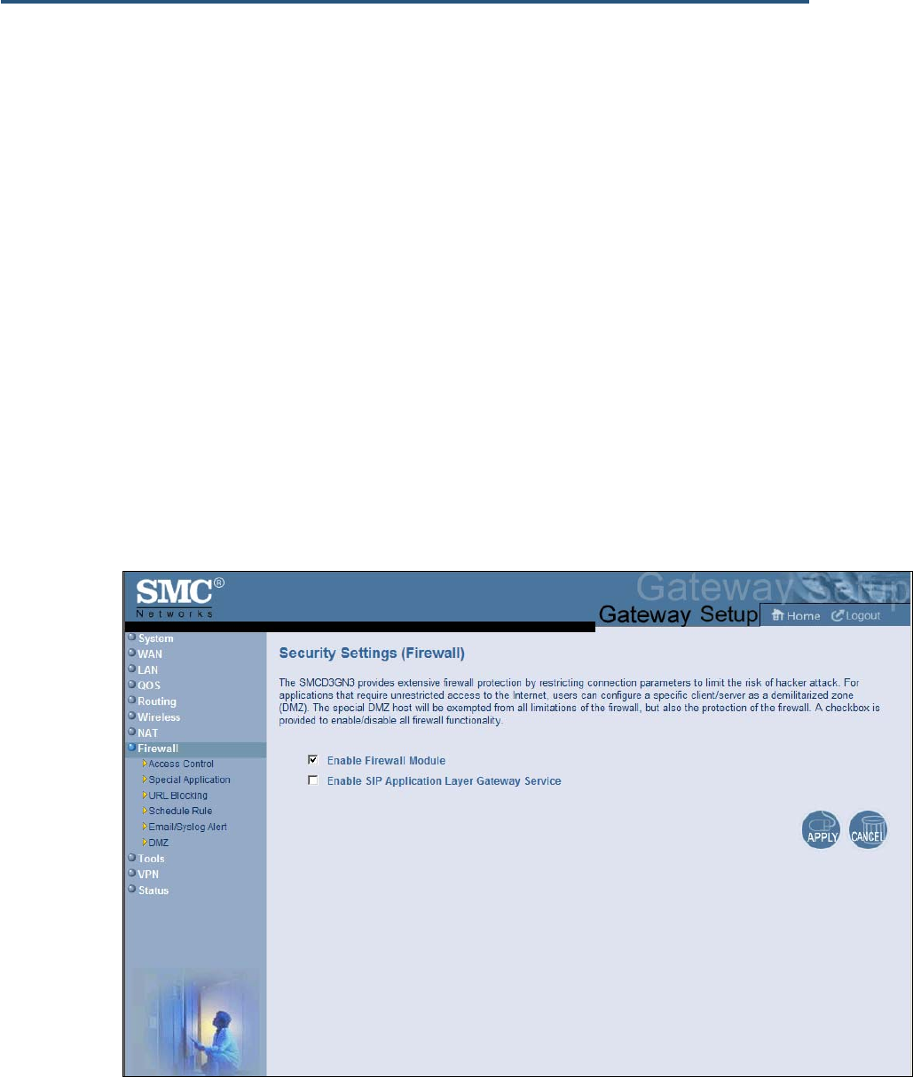
錯誤! 尚未定義樣式。
109
SMCD3GN2 Wireless Cable Modem Gateway Administrator Manual
Security Settings (Firewall) Menu
The Security Settings (Firewall) menu lets you enable or disable the Gateway’s firewall.
If you enable the Gateway firewall module, the following submenus appear in the menu bar:
y Configure access control settings ⎯ see page 107
y Configure the Gateway for special applications ⎯ see page 108
y Set up URL blocking ⎯ see page 122
y Schedule routes ⎯ see page 124
y Receive email or syslog alert notifications ⎯ see page 125
y Configure a local client computer as a local DMZ for unrestricted two-way Internet
access ⎯ see page 129
Enabling or Disabling Firewall
The Security Settings (Firewall) menu provides an option for enabling or disabling the
Gateway’s firewall setting. To access the Security Settings (Firewall)
menu, click Firewall in the menu bar.
Figure 56 shows an example of the menu.
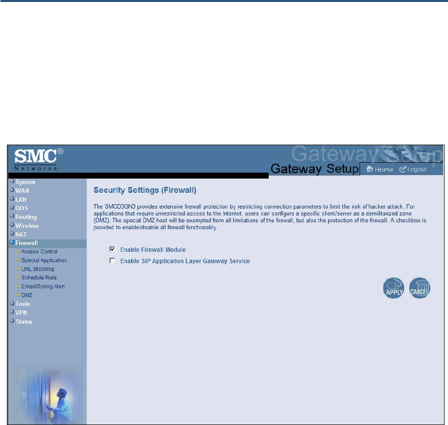
錯誤! 尚未定義樣式。
110
SMCD3GN2 Wireless Cable Modem Gateway Administrator Manual
By default, the Gateway’s firewall settings are enabled. To disable the firewall, uncheck
Enable Firewall Module and click Apply. Disabling the firewall hides the submenus below
the Firewall menu.
The Security Settings (Firewall) menu also provides an option for enabling or disabling the
Session Initiation Protocol (SIP) application-layer gateway service on the Gateway firewall.
This option allows SIP signaling requests to traverse directly through the Gateway to the
destination device.
Figure 56. Security Settings (Firewall) Menu
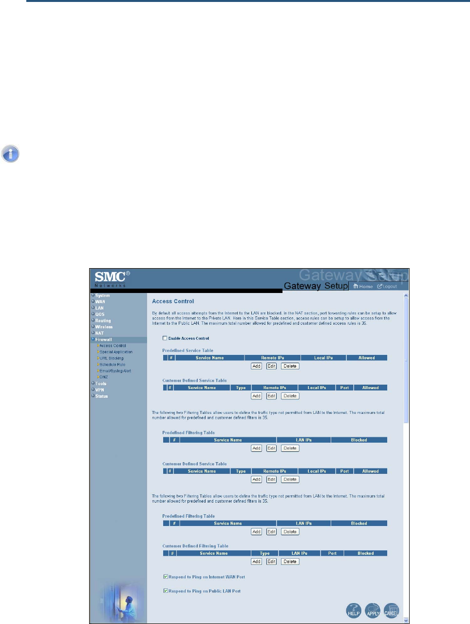
錯誤! 尚未定義樣式。
111
SMCD3GN2 Wireless Cable Modem Gateway Administrator Manual
Configuring Access Control
The Access Control menu lets you enable access control to block traffic at the Gateway's
LAN interfaces from accessing the Internet.
To access the Access Control menu, click Firewall in the menu bar and then click the
Access Control submenu in the menu bar.
Note: The Access Control submenu is not available in the menu bar if Enable
Firewall Module is disabled in the Security Settings (Firewall) menu (see page
105).
By default, the Gateway does not block attempts to access the LAN from the Internet. To
enable access control, check Enable Access Control if it is unchecked and click Apply.
When Access Control is enabled, you can configure up to 35 predefined and customer-
defined filtering tables.
Figure 57. Access Control Menu

錯誤! 尚未定義樣式。
112
SMCD3GN2 Wireless Cable Modem Gateway Administrator Manual
Adding Predefined Access Rules
Using the following procedure, you can select a well-known service and specify whether to
block all LAN hosts, a single LAN host, or a range of LAN hosts.
1. In the Access Control menu, check Enable Access Control if it is not checked and click
the Apply button. The remaining fields in the menu become available.
2. Under Predefined Service Table, click the Add button. The Predefined Access Rules
menu appears (see Figure 58).
3. Complete the fields in the Predefined Access Rules menu (see Table 27).
4. Click Apply. (Or click Back to return to the Access Control menu or Cancel to cancel any
selections you made.) If you clicked Apply, the rule for the predefined access rule is added
to the Predefined Service Table.
5. To configure additional access control rules for predefined services (up to 35, including
access rules for customer-defined services), repeat steps 1 through 4. When you finish,
click Apply in the Access Control menu to save your settings.
6. To change the rule for a predefined rule, click the radio button to the left of the rule you
want to change and click the Edit button. When the Predefined Access Rules menu
appears, edit the settings as necessary (see Table 27) and click Apply. Click Apply in the
Access Control menu to save your settings.
7. To delete a predefined rule, click the radio button to the left of the rule you want to delete
and click the Delete button. No precautionary message appears before you delete a rule.
Click Apply in the Access Control menu to save your settings.
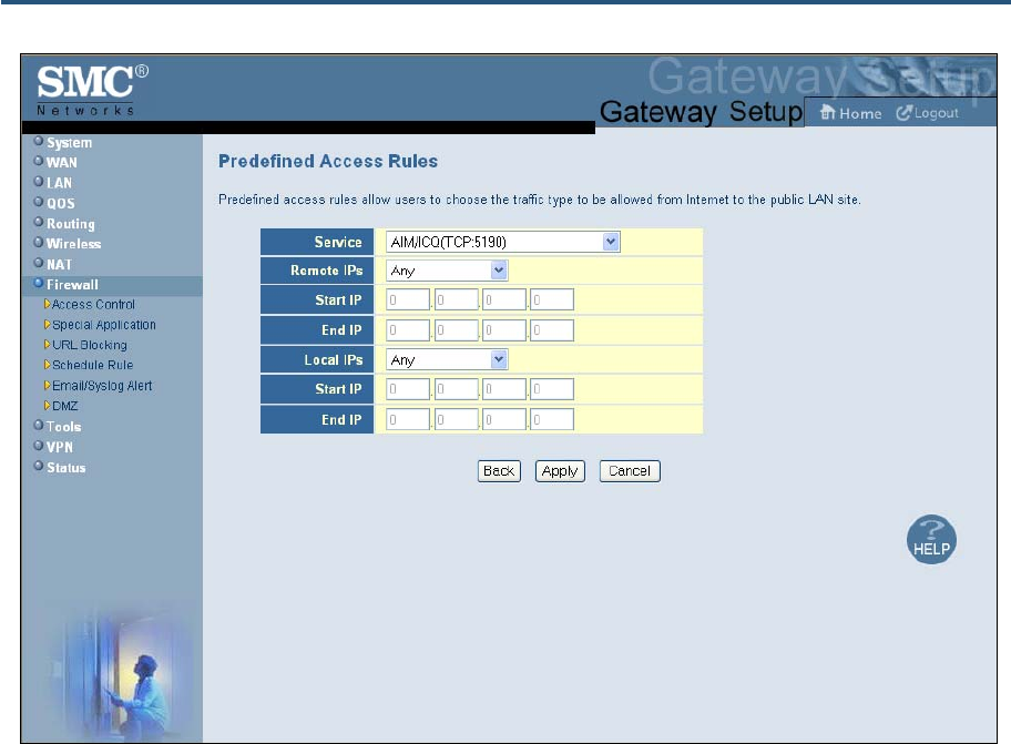
錯誤! 尚未定義樣式。
113
SMCD3GN2 Wireless Cable Modem Gateway Administrator Manual
Figure 58. Predefined Access Rules Menu
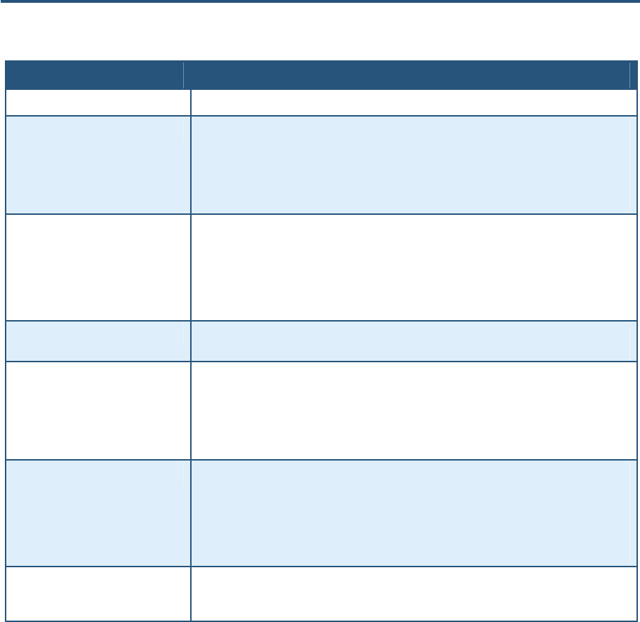
錯誤! 尚未定義樣式。
114
SMCD3GN2 Wireless Cable Modem Gateway Administrator Manual
Table 27. Predefined Access Rules Menu Options
Option Description
Service List of predefined services from which you can choose.
Remote IPs Allows access to any remote IP address, one remote IP address, or a range of remote IP
addresses.
• If you select one remote IP address, enter the IP address in the Start IP field.
• If you select a range of remote IP addresses, enter the starting IP address in the Start IP
field and the ending IP address in the End IP field.
Start IP To forward to:
• A single remote IP address, enter the remote IP address.
• A range of remote IP addresses, enter the starting IP address here and the ending IP
address range in the next field.
This field is unavailable if the Gateway is configured for any remote IP addresses.
End IP Enter the ending IP address in the remote IP address range. This field is unavailable if the
Gateway is configured for any remote IP addresses or for a single remote IP address.
Local IPs Lets you specify any local IP addresses, a single local IP address, or a range of local IP
addresses to which the access rule is applied.
• If you select one local IP address, enter the IP address in the Start IP field.
• If you select a range of local IP addresses, enter the starting IP address in the Start IP field
and the ending IP address in the End IP field.
Start IP To apply the predefined access rule to:
• A single local IP address, enter the local IP address.
• A range of local IP addresses, enter the starting IP address here and the ending IP address
range in the next field.
This field is unavailable if the Gateway is configured for any local IP addresses.
End IP Ending IP address in the local IP address range to which the access rule will be applied. This
field is unavailable if the Gateway is configured for any local IP address or a single local IP
address.

錯誤! 尚未定義樣式。
115
SMCD3GN2 Wireless Cable Modem Gateway Administrator Manual
Adding Customer-Defined Access Rules
Using the following procedure, you can define your own rules regarding the type of traffic
allowed from the Internet to the public LAN site.
1. In the Access Control menu, check Enable Access Control if it is not checked and click
the Apply button. The remaining fields in the menu become available.
2. Under Customer Defined Service Table, click the Add button. The Customer Defined
Access Rules menu appears (see Figure 59).
3. Complete the fields in the Customer Defined Access Rules menu (see Table 28).
4. Click Apply. (Or click Back to return to the Access Control menu or Cancel to cancel any
selections you made.) If you clicked Apply, the rule for the customer-defined rule is added
to the Customer Defined Service Table.
5. To configure additional access control rules for customer-defined services (up to 35,
including access rules for predefined services), repeat steps 1 through 4. When you finish,
click Apply in the Access Control menu to save your settings.
6. To change the rule for a customer-defined service, click the radio button to the left of the
rule you want to change and click the Edit button. When the Customer-Defined Access
Rules menu appears, edit the settings as necessary (see Table 28) and click Apply. Click
Apply in the Access Control menu to save your settings.
7. To delete a customer-defined rule, click the radio button to the left of the rule you want to
delete and click the Delete button. No precautionary message appears before you delete a
rule. Click Apply in the Access Control menu to save your settings.
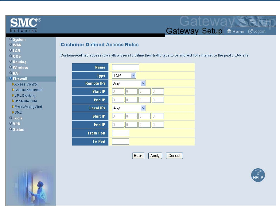
錯誤! 尚未定義樣式。
116
SMCD3GN2 Wireless Cable Modem Gateway Administrator Manual
Figure 59. Customer Defined Access Rules Menu

錯誤! 尚未定義樣式。
117
SMCD3GN2 Wireless Cable Modem Gateway Administrator Manual
Table 28. Customer Defined Access Rules Menu Options
Option Description
Name Name for identifying the custom service. The name is for reference purposes only.
Type The type of protocol you want to access rule. Choices are TCP, UDP, and TCP/UDP. Default
is TCP.
Remote IPs Lets you apply the access rule to any remote IP addresses, a single remote IP address, or a
range of remote IP addresses.
• If you select one remote IP address, enter the IP address in the Start IP field.
• If you select a range of remote IP addresses, enter the starting IP address in the Start IP
field and the ending IP address in the End IP field.
Start IP To specify:
• A single remote IP address, enter the remote IP address.
• A range of remote IP addresses, enter the starting IP address here and the ending IP
address range in the next field.
This field is unavailable if the Gateway is configured for any remote IP addresses.
End IP Ending IP address in the LAN IP address range to which the access rule will be applied. This
field is unavailable if the Gateway is configured for any LAN IP address or a single LAN IP
address.
Local IPs Lets you specify any local IP addresses, a single local IP address, or a range of local IP
addresses to which the access rule is applied.
• If you select one local IP address, enter the IP address in the Start IP field.
• If you select a range of local IP addresses, enter the starting IP address in the Start IP field
and the ending IP address in the End IP field.
Start IP To apply the predefined access rule to:
• A single local IP address, enter the local IP address.
• A range of local IP addresses, enter the starting IP address here and the ending IP address
range in the next field.
This field is unavailable if the Gateway is configured for any local IP addresses.
End IP Ending IP address in the local IP address range to which the access rule will be applied. This
field is unavailable if the Gateway is configured for any local IP address or a single local IP
address.
From Port Starting port number on which the access rule will be applied. If necessary, contact the
application vendor for this information.
To Port Ending port number on which the access rule will be applied. If necessary, contact the
application vendor for this information.

錯誤! 尚未定義樣式。
118
SMCD3GN2 Wireless Cable Modem Gateway Administrator Manual
Adding Predefined Filters
Using the following procedure, you can add predefined filters that block certain types of
traffic from the LAN side of the Gateway to the Internet side of the Gateway .
1. In the Access Control menu, check Enable Access Control if it is not checked and click
the Apply button. The remaining fields in the menu become available.
2. Under Predefined Filtering Table, click the Add button. The Predefined Filter menu
appears (see Figure 60).
3. Complete the fields in the Predefined Filter menu (see Table 29).
4. Click Apply. (Or click Back to return to the Access Control menu or Cancel to cancel any
selections you made.) If you clicked Apply, the predefined filter is added to the Predefined
Filtering Table.
5. To define additional filters for access control (up to 35, including customer-defined filters),
repeat steps 1 through 4. When you finish, click Apply in the Access Control menu to save
your settings.
6. To change the settings for a predefined filter, click the radio button to the left of the service
you want to change and click the Edit button. When the Predefined Filter menu appears,
edit the settings as necessary (see Table 29) and click Apply. Click Apply in the Access
Control menu to save your settings.
7. To delete a predefined filter, click the radio button to the left of the filter you want to delete
and click the Delete button. No precautionary message appears before you delete a
predefined filter. Click Apply in the Access Control menu to save your settings.
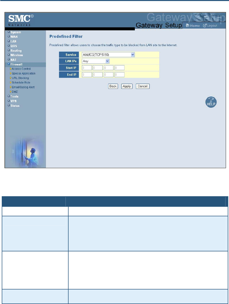
錯誤! 尚未定義樣式。
119
SMCD3GN2 Wireless Cable Modem Gateway Administrator Manual
Figure 60. Predefined Filter Menu
Table 29. Predefined Filter Menu Options
Option Description
Service List of predefined services from which you can choose.
LAN IPs Lets you apply the filter to any LAN IP addresses, a single LAN IP address, or a range of LAN
IP addresses.
• If you select one LAN IP address, enter the IP address in the Start IP field.
• If you select a range of LAN IP addresses, enter the starting IP address in the Start IP field
and the ending IP address in the End IP field.
Start IP To apply the predefined filter to:
• A single local IP address, enter the local IP address.
• A range of local IP addresses, enter the starting IP address here and the ending IP address
range in the next field.
This field is unavailable if the Gateway is configured for any local IP addresses.
End IP Ending IP address in the local IP address range to which the filter will be applied. This field is
unavailable if the Gateway is configured for any local IP address or a single local IP address.

錯誤! 尚未定義樣式。
120
SMCD3GN2 Wireless Cable Modem Gateway Administrator Manual
Adding Customer-Defined Filters
Using the following procedure, you can add customer-defined filters that block certain types
of traffic from the LAN side of the Gateway to the Internet side of the Gateway.
1. In the Access Control menu, check Enable Access Control if it is not checked and click
the Apply button. The remaining fields in the menu become available.
2. Under Customer Defined Filtering Table, click the Add button. The Customer Defined
Filter menu appears (see Figure 61).
3. Complete the fields in the Customer Defined Filter menu (see Table 30).
4. Click Apply. (Or click Back to return to the Access Control menu or Cancel to cancel any
selections you made.) If you clicked Apply, the customer-defined filter is added to the
Customer Defined Filtering Table.
5. To define additional filters for access control (up to 35, including predefined filters), repeat
steps 1 through 4. When you finish, click Apply in the Access Control menu to save your
settings.
6. To change the settings for a customer-defined filter, click the radio button to the left of the
filter you want to change and click the Edit button. When the Customer Defined Filter
menu appears, edit the settings as necessary (see Table 30) and click Apply. Click Apply
in the Access Control menu to save your settings.
7. To delete a customer-defined filter, click the radio button to the left of the filter you want to
delete and click the Delete button. No precautionary message appears before you delete a
customer-defined filter. Click Apply in the Access Control menu to save your settings.

錯誤! 尚未定義樣式。
121
SMCD3GN2 Wireless Cable Modem Gateway Administrator Manual
Figure 61. Customer Defined Filter Menu
錯誤! 尚未定義樣式。
122
SMCD3GN2 Wireless Cable Modem Gateway Administrator Manual
Table 30. Customer Defined Filter Menu Options
Option Description
Name Name for identifying the custom service. The name is for reference purposes only.
Type The type of protocol you want to filter. Choices are TCP, UDP, and TCP/UDP. Default is TCP.
LAN IPs Lets you apply the filter to any LAN IP addresses, a single LAN IP address, or a range of LAN
IP addresses.
• If you select one LAN IP address, enter the IP address in the Start IP field.
• If you select a range of LAN IP addresses, enter the starting IP address in the Start IP field
and the ending IP address in the End IP field.
Start IP To specify:
• A single remote IP address, enter the remote IP address.
• A range of remote IP addresses, enter the starting IP address here and the ending IP
address range in the next field.
This field is unavailable if the Gateway is configured for any remote IP addresses.
End IP Ending IP address in the LAN IP address range to which the filter will be applied. This field is
unavailable if the Gateway is configured for any LAN IP address or a single LAN IP address.
From Port Starting port number on which the filter will be applied. If necessary, contact the application
vendor for this information.
To Port Ending port number on which the filter will be applied. If necessary, contact the application
vendor for this information.
Responding to or Ignoring Pings
When the Gateway firewall module is enabled, the Gateway can respond to pings sent to its
WAN port from an external IP over the Internet and sent to its public LAN port.
To have the WAN port of the Gateway ignore ping requests from the Internet that are sent to
the Gateway’s WAN IP address, uncheck Respond to Ping on Internet WAN Port at the
bottom of the Access Control menu and click Apply.
To have the public LAN port of the Gateway ignore ping requests from the Internet that are
sent to the Gateway’s WAN IP address, uncheck Respond to Ping on Public LAN Port at
the bottom of the Access Control menu and click Apply.

錯誤! 尚未定義樣式。
123
SMCD3GN2 Wireless Cable Modem Gateway Administrator Manual
Configuring Special Applications
Using the Special Application menu, you can configure the Gateway to detect port triggers
for detect multiple-session applications and allow them to pass the firewall. For special
applications, besides the initial communication session, there are multiple related sessions
created during the protocol communications. Normally, a normal treats the triggered
sessions as independent sessions and blocks them. However, the Gateway can co-relate
the triggered sessions with the initial session and group them together in the NAT session
table. As a result, you need only specify which protocol type and port number you want to
track, as well as some other related parameters. In this way, the Gateway can pass the
special applications according to the supplied information.
Assume, for example, that to use H.323 in a Net Meeting application, a local client starts a
session A to a remote host. The remote host uses session A to communicate with the local
host, but it also could initiate another session B back to the local host. Since there is only
session A recorded in the NAT session table when the local host starts the communication,
session B is treated as an illegal access from the outside and is blocked. Using the Special
Application menu, you can configure the Gateway to co-relate sessions A and B and
automatically open the port for the incoming session B.
To display the Special Applications menu, click Firewall in the menu bar and then click the
Special Application submenu. Figure 62 shows an example of the menu.
The maximum allowed triggers is 50. To enable the special application function, check the
Enable Triggering checkbox and click Apply. To disable it, uncheck the Enable Triggering
checkbox and click Apply.
Note: The Special Application submenu is not available in the menu bar if
Enable Firewall Module is disabled in the Security Settings (Firewall) menu (see
page 105).
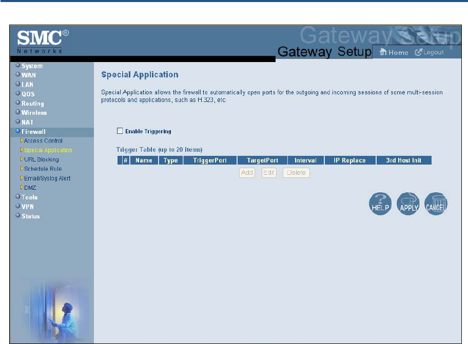
錯誤! 尚未定義樣式。
124
SMCD3GN2 Wireless Cable Modem Gateway Administrator Manual
Figure 62. Special Application Menu
To enable port triggering:
1. In the Special Application menu, check Enable Triggering if it is unchecked and click the
Apply button. The Trigger Table becomes available.
2. Click the Add button below Trigger Table. The Trigger menu appears (see Figure 63).
3. Complete the fields in fields Trigger menu (see Table 31).
4. Click Apply. (Or click Back to return to the Trigger menu or Cancel to cancel any
selections you made.) If you clicked Apply, the trigger is added to the Trigger Table.
5. To configure additional triggers (up to 20), repeat steps 1 through 4. When you finish, click
Apply in the Special Applications menu to save your settings.
6. To change the settings for a trigger, click the radio button to the left of the trigger you want
to change and click the Edit button. When the Trigger menu appears, edit the settings as
necessary (see Table 31) and click Apply. Click Apply in the Special Application menu to
save your settings.
7. To delete a trigger, click the radio button to the left of the trigger you want to delete and
click the Delete button. No precautionary message appears before you delete a trigger.
Click Apply in the Special Application menu to save your settings.
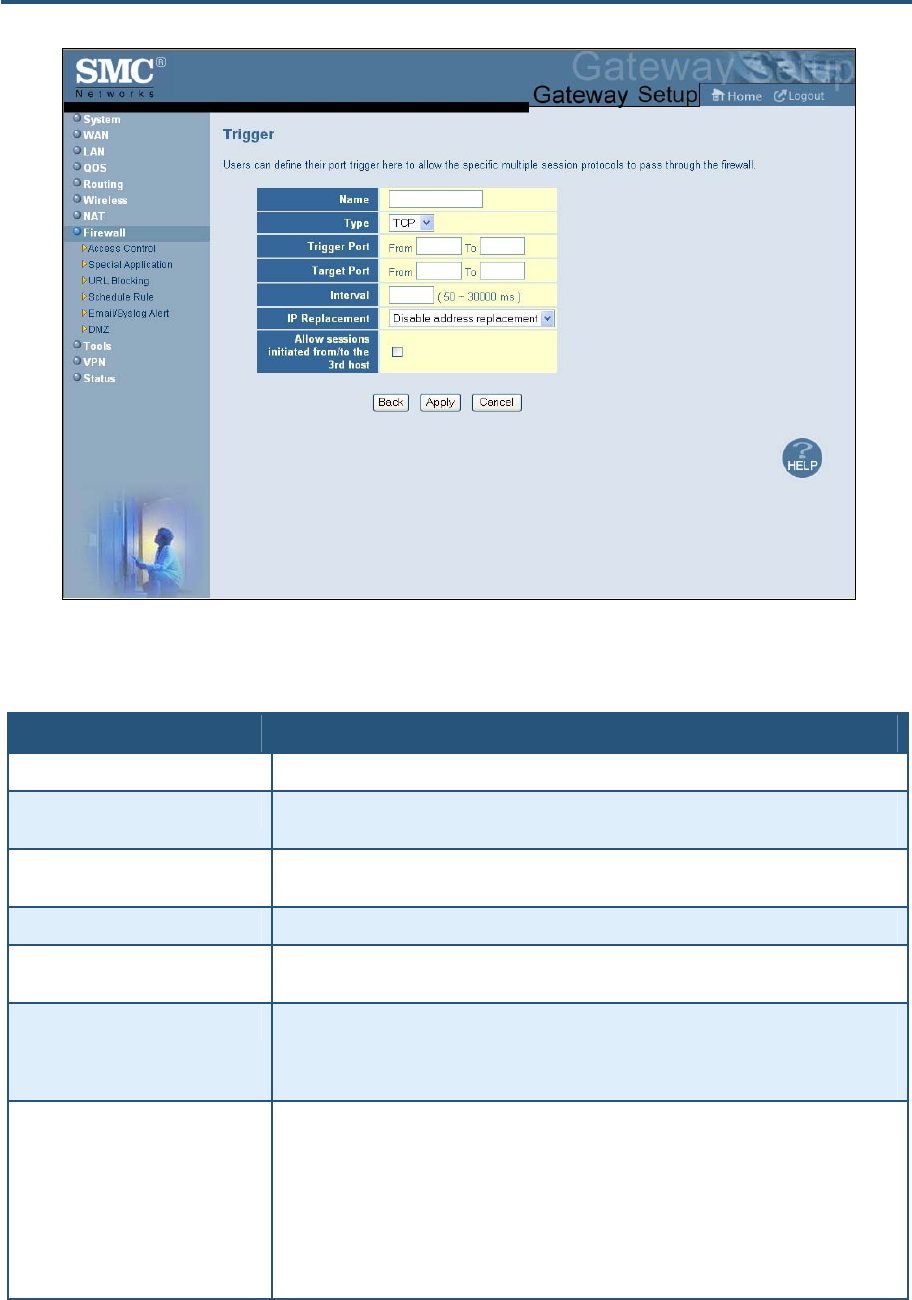
錯誤! 尚未定義樣式。
125
SMCD3GN2 Wireless Cable Modem Gateway Administrator Manual
Figure 63. Trigger Menu
Table 31. Trigger Menu Options
Option Description
Name Name for identifying the trigger. The name is for reference purposes only.
Type The type of protocol you want to use with the trigger. Choices are TCP and UDP. Default is
TCP. For example, to track the H.323 protocol, the protocol type should be TCP.
Trigger Port From and To port ranges of the special application. For example, to track the H.323 protocol,
the From and To ports should be 1720.
Target Port From and To port ranges for the target port listening for the special application.
Interval Specify the interval between 50 and 30000 between two continuous sessions. If the interval
exceeds this time interval setting, the sessions are considered to be unrelated.
IP Replacement Select the IP replacement according to the application. Some applications embed the source
host's IP in the datagram and normal NAT would not translate the IP address in the datagram.
To make sure the network address translation is complete, IP replacement is necessary for
these special applications, such as H.323.
Allow sessions initiated from/to the
3rd host Decide whether the sessions can start from/to a third host. To prevent hacker attacks from a
third host, this feature usually is not allowed. However, for some special applications, such as
MGCP in a VOIP application, a session initiated from a third host is permitted. For example,
assume Client A is trying to make a phone call to a host B. Client A tries to communicate with
the Media Gateway Controller (MGC) first and provides host B's number to MGC. Then MGC
checks its own database to find B and communicate with B to provide B the information about
A. B uses this information to communicate directly to A. So initially, A is talking to MGC, but
the final step has B initiating a session to A. If the third-party host-initiated session is not
allowed in this example, the whole communication fails.

錯誤! 尚未定義樣式。
126
SMCD3GN2 Wireless Cable Modem Gateway Administrator Manual
Configuring URL Blocking
Using the URL Blocking menu, you can configure the Gateway to block access to certain
Web sites from local computers by entering either a full URL address or keywords of the
Web site. The Gateway examines all the HTTP packets to block the access to those
particular sites. This feature can be used to protect children from accessing inappropriate
Web sites. You can block up to 50 sites.
Using URL blocking, you can also make up to 10 computers exempt from URL blocking and
have full access to all Web sites at any time.
To display the URL Blocking menu, click Firewall in the menu bar and then click the URL
Blocking submenu. Figure 64 shows an example of the menu.
Note: The URL Blocking submenu is not available in the menu bar if Enable
Firewall Module is disabled in the Security Settings (Firewall) menu (see page
105).
Tip: The Gateway provides a Schedule Rules feature that lets you configure URL
blocking for certain days, if desired. For more information, see “Configuring
Schedule Rules” on page 124.
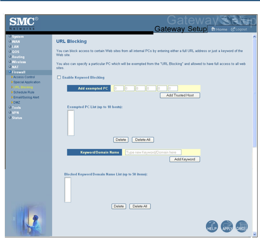
錯誤! 尚未定義樣式。
127
SMCD3GN2 Wireless Cable Modem Gateway Administrator Manual
Figure 64. URL Blocking Menu
To enable URL blocking:
1. In the URL Blocking menu, check Enable Keyword Blocking if it is not checked and click
Apply.
2. To exempt a computer from URL blocking, enter the computer’s MAC address in the Add
exempted PC field and click the Add Trusted Host button. The MAC address you entered
appears in the Exempted PC List.
– Repeat this step for each additional computer (up to 10) you want to make exempt
from URL blocking.
– To remove a computer from being exempted, use the Delete or Delete All buttons
next to the field to delete selected or all MAC addresses.
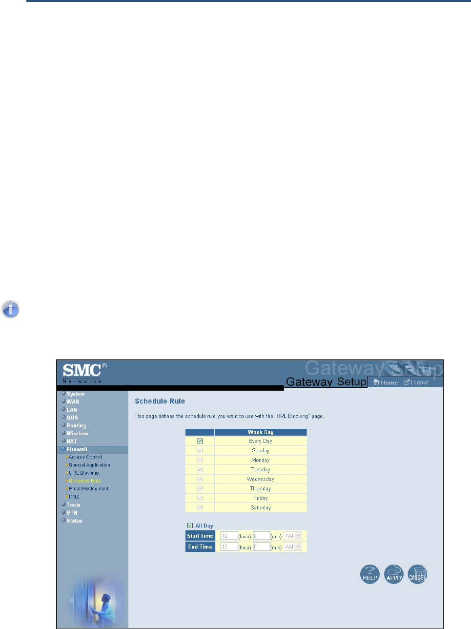
錯誤! 尚未定義樣式。
128
SMCD3GN2 Wireless Cable Modem Gateway Administrator Manual
3. To block a site, click in the Keyword/Domain Name field, enter keyword or domain name
of the site you want to block, and click Add Keyword. The keyword or domain appears in
the Blocked Keyword/Domain List.
– Repeat this step for each additional keyword or domain (up to 50) you want to make
exempt from URL blocking.
– To remove a site from being blocked by a keyword or domain name, use the Delete
or Delete All buttons next to the field to delete selected or all keywords and/or
domains.
4. Click Apply.
Configuring Schedule Rules
Schedule rules work with the Gateway’s URL blocking feature (described on page 122) to
tell the Gateway when to perform URL blocking.
To access the Schedule Rule menu, click Firewall in the menu bar and then click the
Schedule Rule submenu in the menu bar. Figure 65 shows an example of the menu.
Note: The Schedule Rule submenu is not available in the menu bar if Enable
Firewall Module is disabled in the Security Settings (Firewall) menu (see page
105).
Figure 65. Schedule Rule Menu

錯誤! 尚未定義樣式。
129
SMCD3GN2 Wireless Cable Modem Gateway Administrator Manual
By default, the Gateway is configured to apply schedule rules to URL blocking 24 hours
every day. To change these settings:
1. To change the days when schedule rules are applied to URL blocking, uncheck Every Day
under Week Day. Then check the days when you want to apply schedule rules to URL
blocking.
2. To change the hours when schedule rules are applied to URL blocking, uncheck All Day.
Then specify the start and end times when you want to apply schedule rules to URL
blocking. Select AM or PM, where AM refers to times from Midnight to Noon and PM refers
to times from Noon to Midnight.
3. Click Apply.
Configuring Email and Syslog Alerts
The Gateway inspects packets at the application layer, and stores TCP and UDP session
information, including timeouts and number of active sessions. This information is helpful
when detecting and preventing Denial of Service (DoS) and other network attacks.
If you enabled the Gateway’s firewall or content-filtering feature, you can use the
Email/Syslog Alert menu to configure the Gateway to send email notifications or add entries
to the syslog when:
y Traffic is blocked
y Attempts are made to intrude onto the network
y Local computers try to access block URLs
You can configure the Gateway to generate email notifications or syslog entries immediately
or at a preconfigured time.
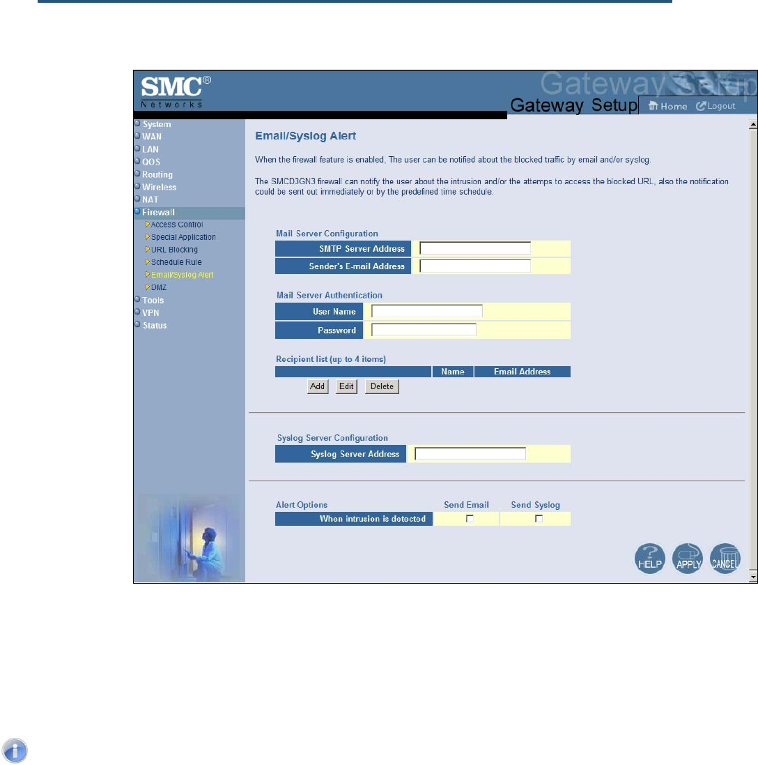
錯誤! 尚未定義樣式。
130
SMCD3GN2 Wireless Cable Modem Gateway Administrator Manual
To access the Email/Syslog Alert menu, click Firewall in the menu bar and then click
the Email/Syslog Alert submenu in the menu bar.
Figure 66 shows an example of the menu. The menu has three sections:
y The top area lets you configure the Gateway to send email notifications.
y The middle area lets you add syslog entries.
y The bottom area lets you define the alerting schedule.
Note: The Email/Syslog Alert submenu is not available in the menu bar if Enable
Firewall Module is disabled in the Security Settings (Firewall) menu (see page
105).
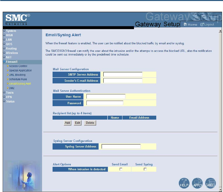
錯誤! 尚未定義樣式。
131
SMCD3GN2 Wireless Cable Modem Gateway Administrator Manual
Figure 66. Email/Syslog Alert Menu
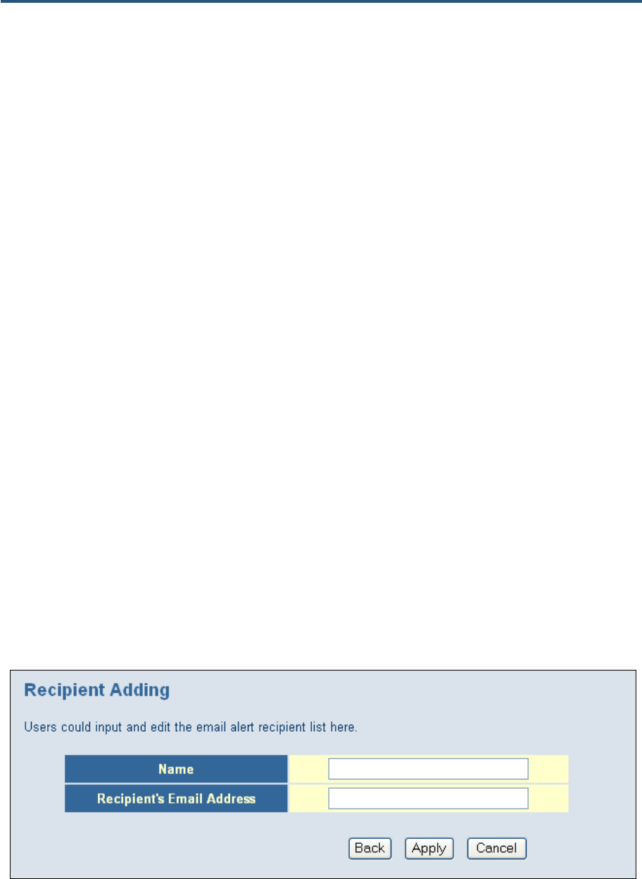
錯誤! 尚未定義樣式。
132
SMCD3GN2 Wireless Cable Modem Gateway Administrator Manual
Configuring Email Alerts
The following procedure describes how to configure the Gateway to send email notifications.
This procedure assumes that your mail server is working properly.
1. In the Email/Syslog Alert menu, under Mail Server Configuration, enter the following
information:
– SMTP Server Address = IP address of the SMTP server that will forward the email
notification to recipients.
– Sender’s Email Address = name that will appear as the sender in the email
notifications.
2. Under Mail Server Authentication, enter the following information:
– User Name = your email name.
– Password = your email password.
3. Under Recipient list, click Add. When the Recipient Adding menu appears (see Figure
67), enter the name of the person who will receive email notifications and the person’s
email address, and then click Apply. (Or click Back to return to the Email/Syslog Alert
menu or Cancel to cancel any selections you made.) If you clicked Apply, the email
account is added to the Recipient list. To send email to additional email accounts (up to 4),
repeat this step.
4. To change the settings for an email recipient, click the radio button to the left of the
recipient you want to change and click the Edit button. When the Recipient Adding menu
appears, edit the settings as necessary and click Apply.
5. To delete an email recipient, click the radio button to the left of the recipient and click
Delete. No precautionary message appears before you delete the email recipient.
6. Click Apply.
Figure 67. Recipient Adding Menu

錯誤! 尚未定義樣式。
133
SMCD3GN2 Wireless Cable Modem Gateway Administrator Manual
Configuring Syslog Entries
To have the Gateway add a syslog entry when traffic is blocked, attempts are made to
intrude onto the network, or local computers try to access block URLs:
1. In the Email/Syslog Alert menu, under Syslog Server Configuration, enter the syslog
server address.
2. Click Apply.
Configuring Alert Options
Using the options in the Alert Options area, you can configure the Gateway to send an
email to recipients you define in this menu and/or send entries to a syslog defined in this
menu if the Gateway detects an intrusion.
To configure the Gateway to send an email to the configured email addresses if it detects an
intrusion:
1. Perform steps 1 through 3 under “Configuring Email Alerts” on page 127.
2. Under Alert Options, check Send Email next to When intrusion is detected.
3. Click Apply.
To configure the Gateway to send an entry to a syslog if it detects an intrusion:
1. Perform step 1 under “Configuring Syslog Entries” on page 128.
2. Under Alert Options, check Send Syslog next to When intrusion is detected.
3. Click Apply.
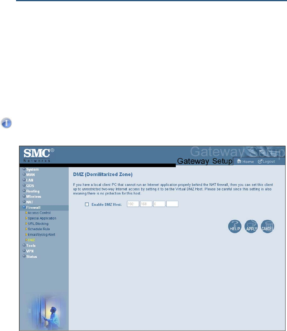
錯誤! 尚未定義樣式。
134
SMCD3GN2 Wireless Cable Modem Gateway Administrator Manual
Configuring DMZ Settings
If you have a local client computer that cannot run an Internet application properly behind
the NAT firewall, you can configure it for unrestricted two-way Internet access by defining it
as a Virtual Demilitarized Zone (DMZ) host. Adding a client to the DMZ may expose your
local network to various security risks because the client in the DMZ is not protected by the
firewall.
To access the DMZ (Demilitarized Zone) menu, click Firewall in the menu bar and then click
the DMZ submenu in the menu bar. Figure 68 shows an example of the menu.
Note: The DMZ submenu is not available in the menu bar if Enable Firewall
Module is disabled in the Security Settings (Firewall) menu (see page 105).
Figure 68. DMZ (Demilitarized Zone) Menu

錯誤! 尚未定義樣式。
135
SMCD3GN2 Wireless Cable Modem Gateway Administrator Manual
To configure DMZ settings:
1. In the DMZ (Demilitarized Zone) menu, check Enable DMZ Host. The 2 rightmost fields
next to this option become available.
2. Enter the last two octets in the IP addresses of the computer to be used as the DMZ server.
3. Click Apply.
Using the Configuration Tools Menu
Gateways often get upgraded or swapped out for a number of reasons. There also times
when a Gateway might fail. In such cases, having a backup file containing your configuration
settings allows you to restore a configuration by importing the configuration settings back
into the Gateway.
Using the Configuration Tools menu, you can:
y Switch working scripts. See page 132.
y Back up the Gateway’s current configuration settings locally. See page 132.
y Restore the configuration settings locally from a back-up copy. See page 133.
y Remotely back up the current configuration settings over the WAN. See page 134.
y Remotely restore the configuration settings from a backup copy over the WAN. See
page 135.
y Restore the Gateway’s factory default settings. See page 136.
To access the Configuration Tools menu, click Tools in the menu bar and then click
the Configuration Tools submenu in the menu bar.

錯誤! 尚未定義樣式。
136
SMCD3GN2 Wireless Cable Modem Gateway Administrator Manual
Figure 69 shows an example of the menu.
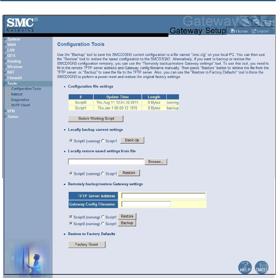
錯誤! 尚未定義樣式。
137
SMCD3GN2 Wireless Cable Modem Gateway Administrator Manual
Figure 69. Configuration Tools Menu
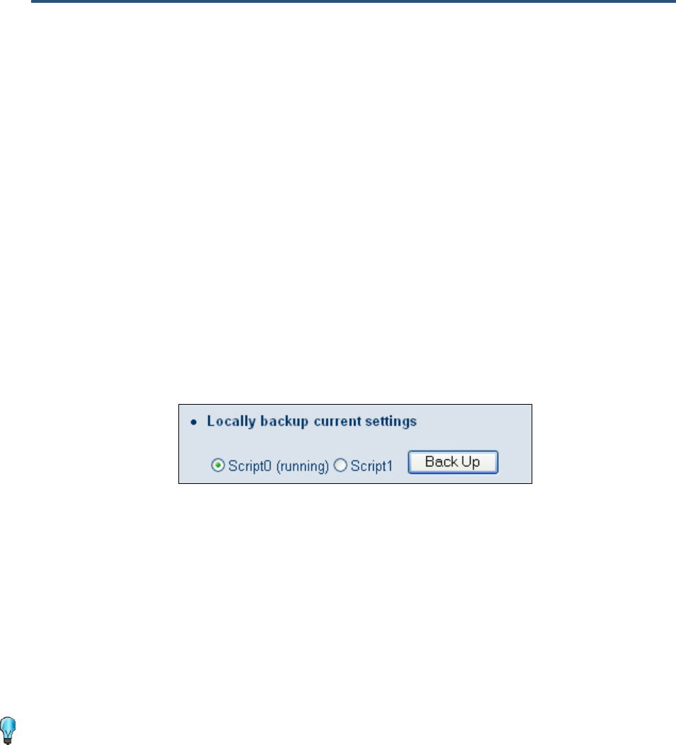
錯誤! 尚未定義樣式。
138
SMCD3GN2 Wireless Cable Modem Gateway Administrator Manual
Switching Working Scripts
If more than one working script appears below Configuration file settings, you can switch
to another working script.
1. Under Configuration file settings, click the Switch Working Script button.
2. When a prompt asks whether you want to switch scripts, click OK to switch or Cancel to
keep the current working script.
Backing Up the Gateway’s Current Configuration Locally
To back up the Gateway’s current configuration locally:
1. If one or more scripts appear to the left of the Back Up button under Locally backup
current settings, click the script you want to back up. (running) appears next to the script
that is currently running.
2. Click the Back Up button.
3. When the File Download dialog box appears (see Figure 70), click Save. (Or click Open to
view the file prior to saving it. If you open the file, you will have to repeat steps 1 and 2 to
save it.)
4. When the Save As dialog box appears, go to the location where you want to save the
configuration file and click the Save button. The file is saved as smc.cfg.
5. When the save operation is complete, the Download complete dialog box appears (see
Figure 71). Click Open to open the configuration file, Open Folder to open the folder
containing the configuration file, or Close to close the dialog box.
Tip: If you click Open and a message tells you that an application could not be
found to open the configuration file, open the file in a text editor such as WordPad.
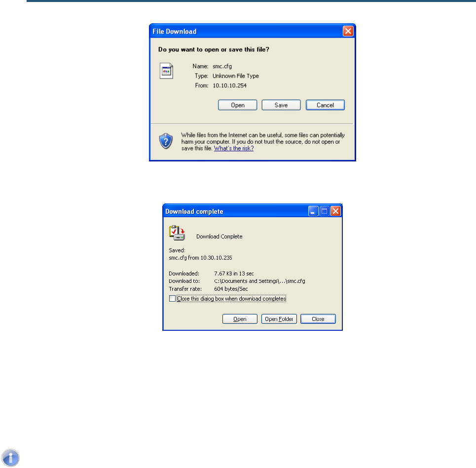
錯誤! 尚未定義樣式。
139
SMCD3GN2 Wireless Cable Modem Gateway Administrator Manual
Figure 70. File Download Dialog Box
Figure 71. Download Complete Dialog Box
Restoring the Gateway’s Current Configuration Locally
If you backed up the Gateway’s configuration settings locally, use the following procedure to
restore the settings locally.
Note: Restoring the Gateway’s settings from a configuration file erases all of the
Gateway’s current settings.
1. If one or more scripts appear to the left of the Restore button under Locally restore
saved settings from file, click the script you want to restore. (running) appears next to
the script that is currently running.
2. Click the Browse button.
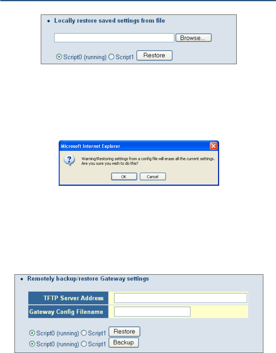
錯誤! 尚未定義樣式。
140
SMCD3GN2 Wireless Cable Modem Gateway Administrator Manual
3. When the Choose File dialog box appears, go to the location where you saved the
smc.cfg file. Then either double-click the file, or click it and click the Open button. The file
path and name appear to the left of the Browse button.
4. Click the Restore button. The message in Figure 72 appears.
5. Click OK to override the Gateway’s current configuration with the one in the configuration
file or click Cancel to not restore the configuration from the file.
Figure 72. Warning Message when Restoring from a Configuration File
Backing Up the Gateway’s Current Configuration Remotely
You can back up the Gateway’s current configuration remotely by uploading the smc.cfg
file to a TFTP server.
1. Under Remotely backup/restore Gateway settings, enter the IP address of the TFTP
server in the TFTP Server Address field.
2. In the Gateway Config Filename field, enter the name of the configuration file.
3. If one or more scripts appear to the left of the Backup button, select the script you want to
restore. (running) appears next to the script that is currently running.
4. Click the Backup button.
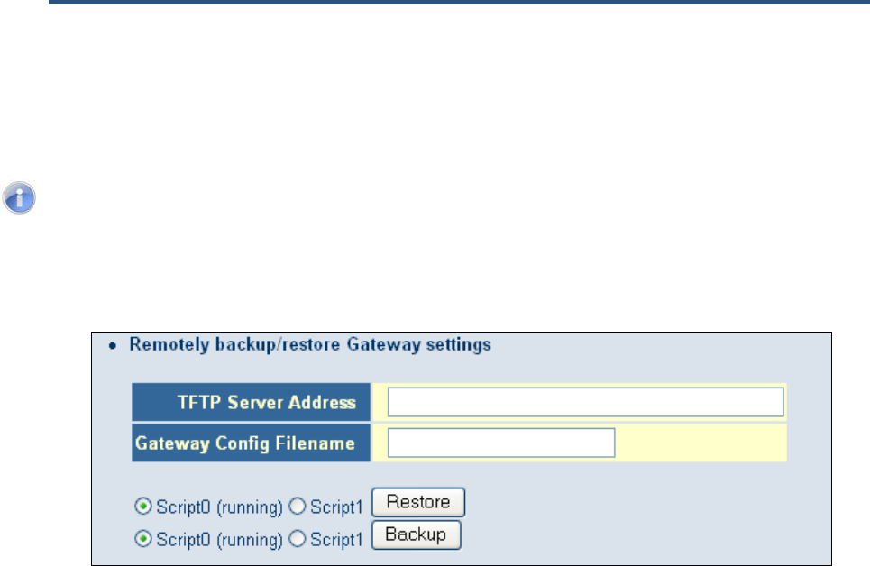
錯誤! 尚未定義樣式。
141
SMCD3GN2 Wireless Cable Modem Gateway Administrator Manual
Restoring the Gateway’s Current Configuration Remotely
If you backed up the Gateway’s configuration settings to a TFTP server, use the following
procedure to restore the settings remotely.
Note: Restoring the Gateway’s settings from a configuration file erases all of the
Gateway’s current settings.
1. Under Remotely backup/restore Gateway settings, enter the IP address of the TFTP
server in the TFTP Server Address field.
2. In the Gateway Config Filename field, enter the name of the configuration file.
3. If one or more scripts appear to the left of the Restore button, select the script you want to
restore. (running) appears next to the script that is currently running.
4. Click the Restore button. The message in Figure 72 appears.
5. Click OK to override the Gateway’s current configuration with the one in the configuration
file or click No to not restore the configuration from the file.
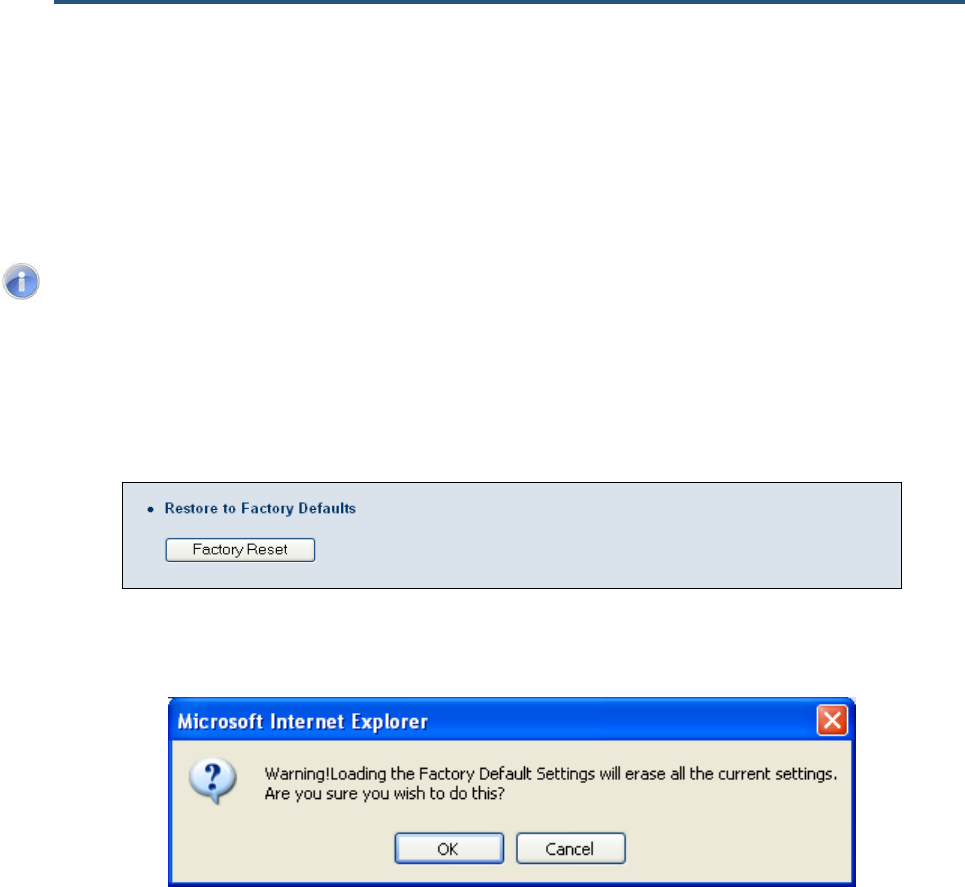
錯誤! 尚未定義樣式。
142
SMCD3GN2 Wireless Cable Modem Gateway Administrator Manual
Restoring Factory Defaults
One way to restore the Gateway’s factory default settings is by using the Reset switch on
the Gateway’s rear panel (see “Restoring Factory Defaults” on page 15). Another way is to
use the Configuration Tools menu to power-cycle the Gateway.
Note: Rebooting the Gateway removes any customized overrides you made to the
default settings. To reboot the Gateway and retain any customized settings, use
the Reboot menu (see “Using the Reboot Menu to Reboot the Gateway“ on page
137).
1. Under Restore to Factory Defaults, click Factory Reset. The warning message in Figure
73 appears.
2. Click OK to restore the Gateway’s factory default settings or click Cancel to retain the
Gateway’s current settings.
Figure 73. Warning Message when Restoring Factory Defaults
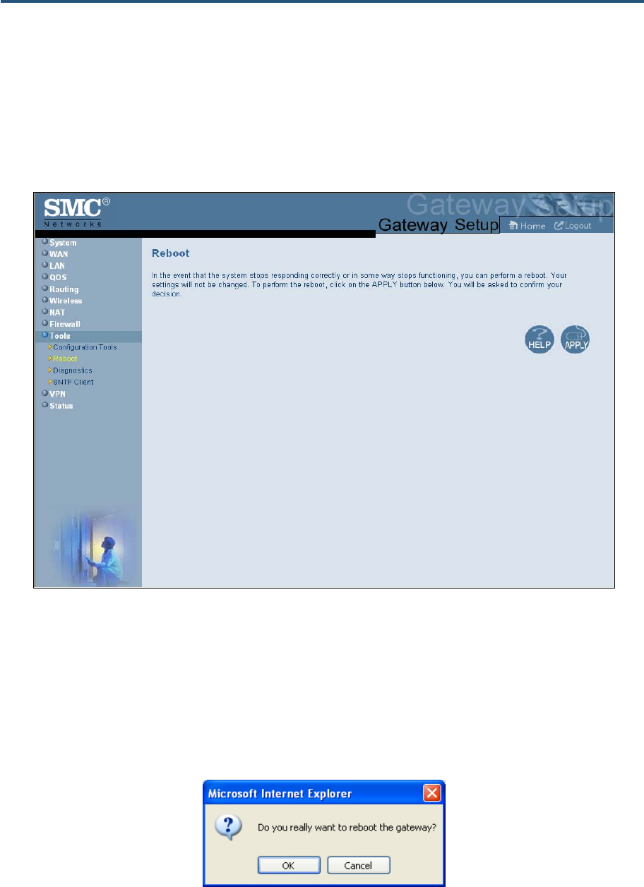
錯誤! 尚未定義樣式。
143
SMCD3GN2 Wireless Cable Modem Gateway Administrator Manual
Using the Reboot Menu to Reboot the Gateway
Using the Reboot menu, you can reset the Gateway and retain all changes that have been
made to the Gateway’s factory default settings. To access the Reboot menu, click Tools in
the menu bar and then click the Reboot submenu in the menu bar. Figure 74 shows an
example of the menu.
Figure 74. Reboot Menu
To reboot the Gateway and retain all changes made to its factory default settings:
1. In the Reboot menu, click Apply. The precautionary message in Figure 75 appears.
2. Click OK to reboot the Gateway or click Cancel to not reboot it. If you clicked OK, the
reboot is complete when the POWER LED stops blinking and you will need to log in to the
Web interface again.
Figure 75. Precautionary Message When Rebooting the Gateway
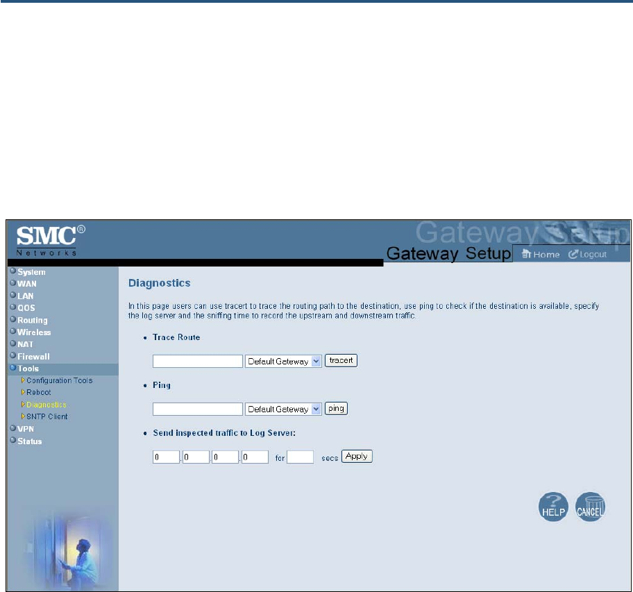
錯誤! 尚未定義樣式。
144
SMCD3GN2 Wireless Cable Modem Gateway Administrator Manual
Using the Diagnostics Menu
The Diagnostics menu lets you use “traceroute” to trace the routing path from the Gateway
to the destination and router, and use ping to ascertain whether the destination is available.
This menu also lets you specify the IP address for a log server, and the sniffing time to
record the upstream and downstream traffic.
To access the Diagnostics menu, click Tools in the menu bar and then click the
Diagnostics submenu in the menu bar. Figure 76 shows an example of the menu.
Figure 76. Diagnostics Menu
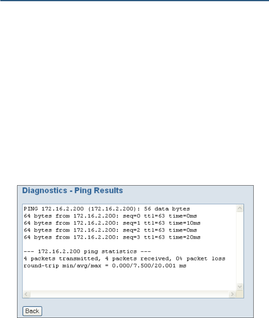
錯誤! 尚未定義樣式。
145
SMCD3GN2 Wireless Cable Modem Gateway Administrator Manual
Using the Ping Tool
Using the ping tool, you can check the connectivity between the Gateway and another local
or remote device. The Gateway provides a ping tool for conducting the ping with the default
Gateway, across the RF interface, or across the WAN interface. This tool sends a small
packet of data and then waits for a reply. When you ping a computer IP address and receive
a reply, it confirms that the device is connected to the Gateway.
To perform ping activities, use the following procedure under Ping on the Diagnostics menu.
1. Enter the IP address or domain name of a target host in the Ping field.
2. In the drop-down list to the right of the IP address or domain name, select whether the ping
is to be sent to the default Gateway, across the Gateway’s RF interface, or across the
Gateway’s WAN interface.
3. Click the ping button. The results appear in the Diagnostics – Ping Results screen (see
Figure 77 and Figure 78). The results screen may flash as the contents refresh during the
ping.
4. To close the results screen, click the Back button.
Figure 77. Example of Results for a Ping
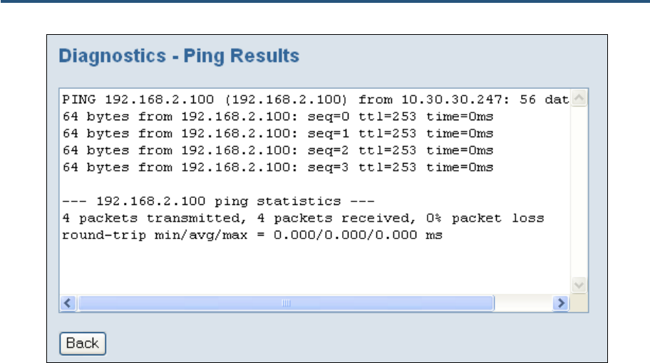
錯誤! 尚未定義樣式。
146
SMCD3GN2 Wireless Cable Modem Gateway Administrator Manual
Figure 78. Example of Results for a WAN Ping

錯誤! 尚未定義樣式。
147
SMCD3GN2 Wireless Cable Modem Gateway Administrator Manual
Using the Trace Route Tool
The Gateway provides a trace route tool for conducting the trace route with the default
Gateway, across the RF interface, or across the WAN interface. This tool provides a
supplemental role to the ping tool. While the ping tool confirms IP network reachability, you
cannot pinpoint and improve some isolated problems.
Consider the following situations:
y When there are many hops (for example, gateways or routes) between the Gateway and
the destination, and there seems to be a problem somewhere along the path. The
destination system may have a problem, but you need to know where a packet is
actually lost.
y The ping tools do not tell you the reasons for a lost packet.
The trace route tool can inform you where the packet is located and why the route is lost.
Using the trace route tools, you can map the network path in real time from the Gateway to a
local or public host.
To perform trace route activities, use the following procedure under Trace Route on the
Diagnostics menu.
1. Enter the IP address or domain name of a target host in the Trace Route field.
2. In the drop-down list to the right of the IP address or domain name, select whether the
trace route is to be sent to the default Gateway, across the Gateway’s RF interface, or
across the Gateway’s WAN interface.
3. Click the tracert button. The trace route results appear in the Diagnostics – Trace Route
Results screen, as the Gateway sends UDP packets to each device between the Gateway
and the destination (see Figure 79 and Figure 80). It starts with the nearest device and
expands the search by one hop until the destination is reached or the trace route times out.
The results screen may flash as the contents refresh during the trace route operation.
4. To close the screen, click the Back button.
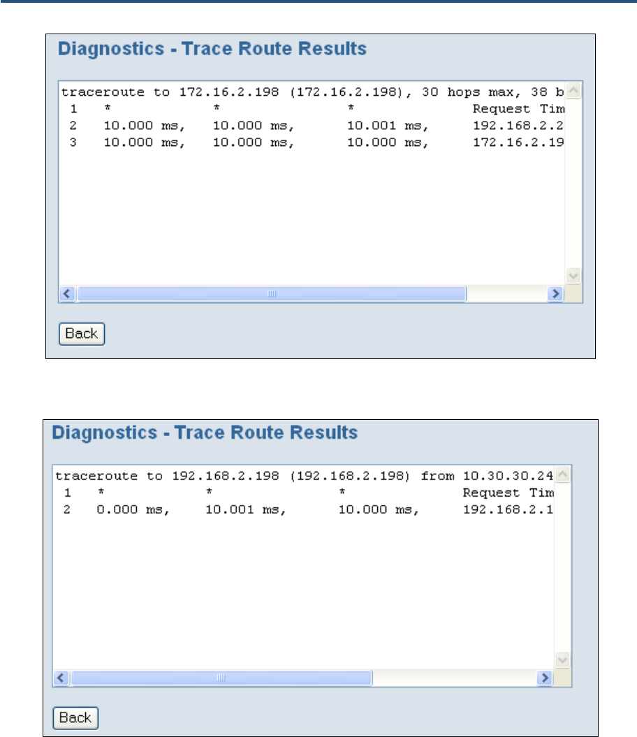
錯誤! 尚未定義樣式。
148
SMCD3GN2 Wireless Cable Modem Gateway Administrator Manual
Figure 79. Example of Results for Trace Route
Figure 80. Example of Results for a WAN Trace Route
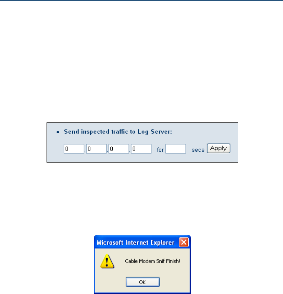
錯誤! 尚未定義樣式。
149
SMCD3GN2 Wireless Cable Modem Gateway Administrator Manual
Sending Inspected Traffic to a Log Server
The Gateway can inspect upstream and downstream traffic, and log the results to the syslog
server, where they can be further examined.
To send inspected traffic to a log server, perform the following procedure under Send
inspected traffic to Log Server on the Diagnostics menu.
1. In the first four fields, enter the IP address of the log server.
2. In the for field, enter the number of seconds that inspected traffic is to be sent to the log
server.
3. Click the Apply button.
4. The Gateway sniffs the traffic, logs the traffic to the syslog, and displays the message in
Figure 81 when the number of seconds elapses.
5. Click OK to close the message.
You can now examine the sniffed traffic using appropriate syslog daemons and applications.
Figure 81. Sniffing Complete Message
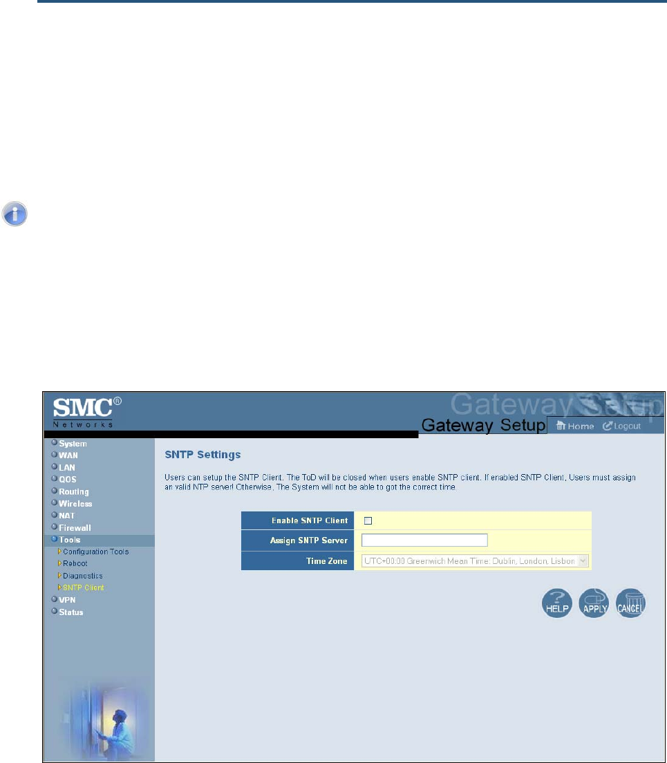
錯誤! 尚未定義樣式。
150
SMCD3GN2 Wireless Cable Modem Gateway Administrator Manual
Using the SNTP Menu
The SNTP Settings menu lets you configure the Gateway to act as an SNTP client. SNTP is
a simplified, client-only version of NTP, a standard protocol used to synchronize system
clocks on computer systems. SNTP can be enabled on the Gateway to keep the Gateway’s
time accurate up to fractions of a second. The service is constantly updating the Gateway’s
clock, and can be used as a master time source for other systems on your network.
Note: While SNTP typically provides time within 100 milliseconds of the accurate
time, it does not provide the complex filtering and statistical mechanisms of NTP. In
addition, SNTP does not authenticate traffic. An SNTP client is more vulnerable to
misbehaving servers than an NTP client, and should only be used in situations
where strong authentication is not required.
To access the SNTP Settings menu, click Tools in the menu bar and then click the SNTP
Client submenu in the menu bar. Figure 82 shows an example of the menu and Table 32
describes the options you can select.
Figure 82. SNTP Settings Menu
錯誤! 尚未定義樣式。
151
SMCD3GN2 Wireless Cable Modem Gateway Administrator Manual
Table 32. SNTP Settings Menu Options
Option Description
Enable SNTP Client Enables or disables the Gateway to be set up as an SNTP client.
• Checked = Gateway can be set up as an SNTP client. The remaining fields in the menu
become available.
• Unchecked = Gateway cannot be set up as an SNTP client. The remaining fields in the
menu remain gray and unavailable. (default)
Assign SNTP Server IP address or host name of the SNTP server. This field is not available if Enable SNTP Client
is not checked.
Time Zone Time zone to be used for SNTP operations. This field is not available if Enable SNTP Client is
not checked.
Configuring VPN Settings
A Virtual Private Network (VPN) is a technology designed to increase the security of
information transferred over the Internet. A VPN creates a private encrypted tunnel from the
user's computer, through the local wireless network, through the Internet, all the way to the
corporate servers and database.
The Gateway supports the Internet Protocol Security (IPSec) to secure IP traffic. IPSec
builds “virtual tunnels” between a local and remote subnet for secure communication
between two networks. This connection is commonly known as a Virtual Private Network
(VPN).
Alternatively, tunneling protocols such as L2TP and PPTP can be used to achieve a secure
connection (such as to a corporate LAN) over the Internet. These tunneling protocols can
optionally be secured themselves using IPSec.
Using the VPN menu, you can enable or disable the Gateway’s VPN settings. If the VPN
settings are enabled, you can use VPN submenus to:
y Allow PC clients behind the Gateway to access the IPSec VPN tunnel. See page 147.
y Define the VPN tunnel configuration. See page 148.
Using the VPN Menu
You can use the VPN menu to enable or disable the Gateway’s VPN functions. By default,
the Gateway’s Virtual Private Network (VPN) settings are disabled.
To access the VPN menu, click VPN in the menu bar. Figure 83 shows an example of the
menu and Table 33 describes the options you can select.
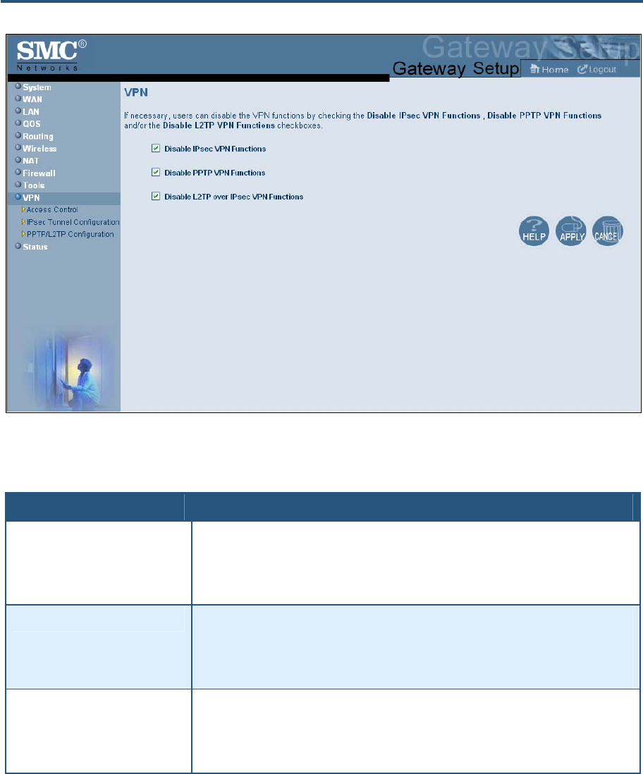
錯誤! 尚未定義樣式。
152
SMCD3GN2 Wireless Cable Modem Gateway Administrator Manual
Figure 83. VPN Menu
Table 33. VPN Menu Options
Option Description
Disable IPsec VPN Functions Lets you enable the Gateway’s IPsec VPN functions. Select the option based on the type of
Internet connection you will provide.
• Checked = functions are disabled. (default)
• Unchecked = functioned are enabled.
Disable PPTP VPN Functions Lets you enable the Gateway’s Point to Point Protocol (PPP) VPN functions. Select the option
based on the type of Internet connection you will provide.
• Checked = functions are disabled. (default)
• Unchecked = functioned are enabled.
Disable L2TP over IPsec VPN
Functions Lets you enable the Gateway’s LT2P VPN functions. Select the option based on the type of
Internet connection you will provide.
• Checked = LT2P VPN functions are disabled. (default)
• Unchecked = LT2P VPN functions are enabled.
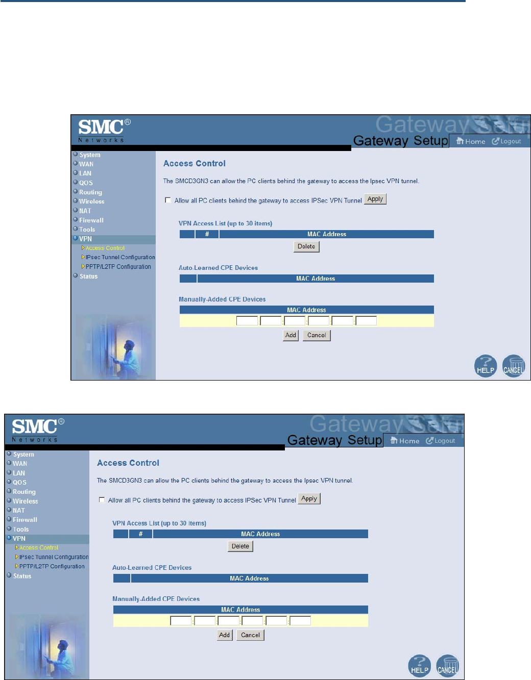
錯誤! 尚未定義樣式。
153
SMCD3GN2 Wireless Cable Modem Gateway Administrator Manual
Using the Access Control Menu to Allow CPEs to Access IPSec VPN Tunnel
You can use the Access Control menu to allow PC clients behind the Gateway to access the
IPSec VPN tunnel.
To access the Access Control menu, click VPN in the menu bar and then click the
Access Control submenu.
Figure 84 shows an example of the menu.

錯誤! 尚未定義樣式。
154
SMCD3GN2 Wireless Cable Modem Gateway Administrator Manual
Figure 84. Access Control Menu
To allow PC clients behind the Gateway to access the IPSec VPN tunnel:
1. Click VPN in the menu bar.
2. On the VPN menu, uncheck Disable IPsec VPN Functions and click Apply (see Figure
83). Otherwise, the Allow all PC clients behind the gateway to access IPSec VPN
Tunnel option in the Access Control menu will be unavailable.
3. In the menu bar, under VPN, click the Access Control submenu.
4. On the Access Control menu, click Allow all PC clients behind the gateway to access
IPSec VPN Tunnel and click Apply. The fields in the menu become available.
5. To add customer premises equipment (CPE) that the Gateway automatically learned on
the network, perform the following steps under Auto-Learned CPE Devices:
a. Click a CPE that the Gateway learned automatically.
b. Click Add to add the CPE to the VPN Access List.
c. To add more auto-learned CPEs (up to 30), repeat steps 5a and 5b.
6. To manually add CPEs, perform the following steps under Manually-Added CPE Devices:
a. Under MAC Address, enter the MAC address of the device.
b. Click Add to add the CPE to the VPN Access List.
c. To manually add more CPEs (up to 30), repeat steps 6a and 6b.
7. To delete CPEs from access control, under VPN Access List, click the radio button
corresponding to the CPE you want to delete and click the Delete button. A precautionary
message does not appear before deleting a CPE.
Using the VPN – Tunnel Configuration Menu
You can use the VPN – Tunnel Configuration menu to define up to five tunnels. This menu
also shows the VPN log and provides buttons for clearing, refreshing, and saving the log to a
drive location.
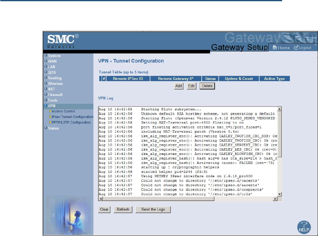
錯誤! 尚未定義樣式。
155
SMCD3GN2 Wireless Cable Modem Gateway Administrator Manual
To access the VPN – Tunnel Configuration menu, click VPN in the menu bar and then
click the IPsec Tunnel Configuration submenu.
Figure 85 shows an example of the menu.
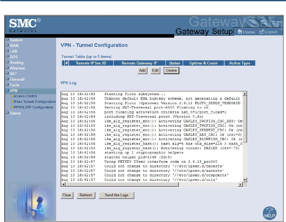
錯誤! 尚未定義樣式。
156
SMCD3GN2 Wireless Cable Modem Gateway Administrator Manual
Figure 85. VPN – Tunnel Configuration Menu
Defining VPN Tunnels
To define VPN tunnels:
1. Click VPN in the menu bar.
2. On the VPN menu, uncheck Disable IPsec VPN Functions and click Apply (see Figure
83). Otherwise, the buttons for adding, editing, and deleting VPN tunnels on the VPN -
Tunnel Configuration menu will be unavailable.
3. In the menu bar, under VPN, click the IPsec Tunnel Configuration submenu.
4. On the VPN – Tunnel Configuration menu, click Add. The VPN – Adding VPN Tunnel
menu in Figure 86 appears.
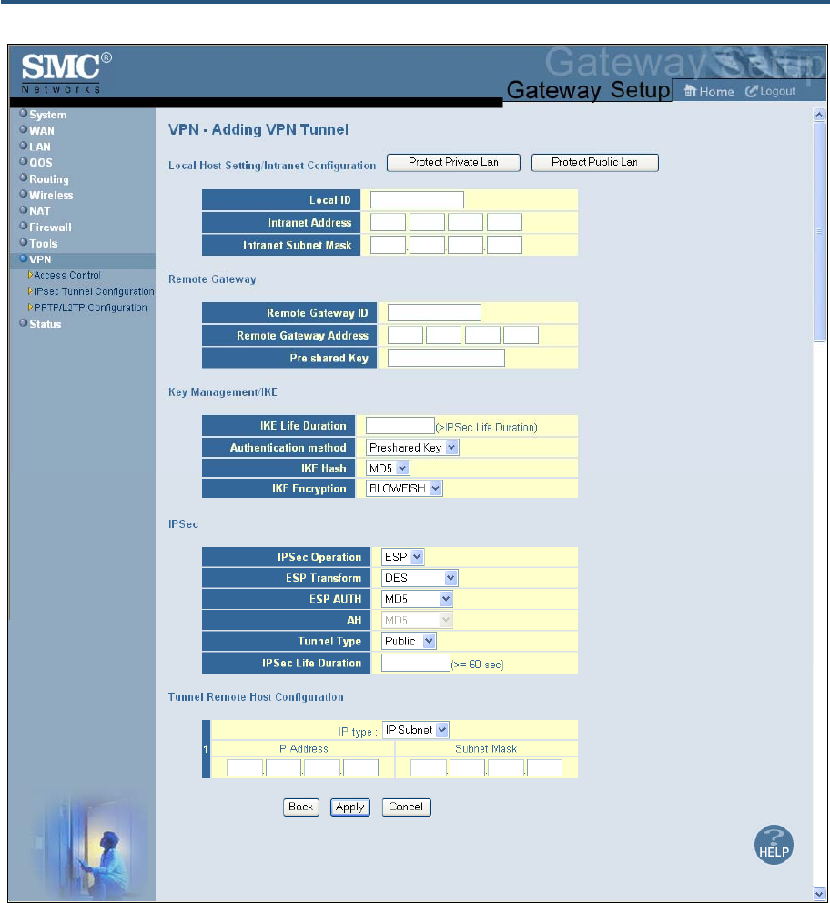
錯誤! 尚未定義樣式。
157
SMCD3GN2 Wireless Cable Modem Gateway Administrator Manual
Figure 86 VPN – Adding VPN Tunnel Menu
5. Complete the fields in the VPN - Adding VPN Tunnel menu (see Table 34).
6. Click Apply. (Or click Back to return to the VPN – Tunnel Configuration menu or Cancel to
cancel any selections you made.) If you clicked Apply, the tunnel is added to the Tunnel
Table.
7. To define additional tunnels (up to five), repeat steps 4 through 6.
8. To change the settings for a tunnel, click the radio button to the left of the tunnel you want
to change and click the Edit button. When the VPN – Adding VPN Tunnel menu appears,
edit the settings as necessary (see Table 34) and click Apply.
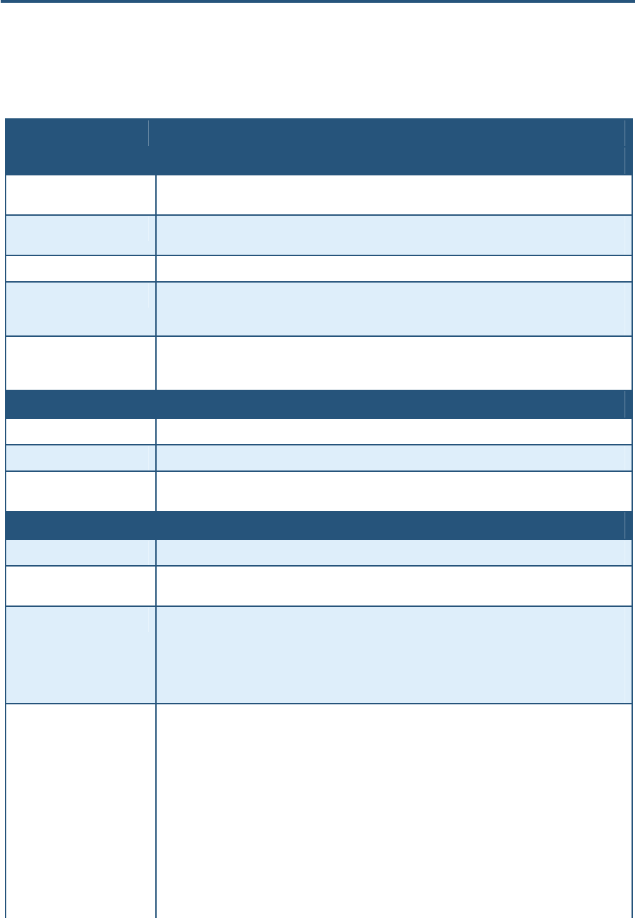
錯誤! 尚未定義樣式。
158
SMCD3GN2 Wireless Cable Modem Gateway Administrator Manual
9. To delete a tunnel, click the radio button to the left of the tunnel you want to delete and
click the Delete button. No precautionary message appears before you delete a tunnel.
Table 34. VPN – Adding VPN Tunnel Menu Options
Option Description
Local Host Setting Intranet Configuration
Protect Private Lan button Click this button to automatically populate the Intranet Address and Intranet Subway Mask fields with
unique private LAN values.
Protect Public Lan button Click this button to automatically populate the Intranet Address and Intranet Subway Mask fields with
unique public LAN values.
Local ID ID to identify and authenticate the local host.
Intranet Address IP address of the local host. You can manually add this information, or use the Protect Private Lan
or Protect Public Lan button to auto-assign a unique IP address for the private or public LAN,
respectively.
Intranet Subnet Mask Subnet mask of the local host. You can manually add this information, or use the Protect Private
Lan or Protect Public Lan button to auto-assign a unique subnet mask for the private or public LAN,
respectively.
Remote Gateway
Remote Gateway ID ID to identify and authenticate the remote gateway at the other end of the VPN tunnel.
Remote Gateway Address IP address of the remote gateway at the other end of the VPN tunnel.
Pre-shared Key A “pass code” that must be the same at both the local and the remote side. Both ends of the tunnel
must use the same key; otherwise, the VPN tunnel cannot be established.
Key Management / IKE
IKE Life Duration Length to time or amount of transfer before the Security Association is renegotiated.
Authentication method Authentication mode used for keying the IPSec connection. Both ends of the tunnel must use the
same setting; otherwise, the VPN tunnel cannot be established.
IKE Hash Checks that the data has not changed in transmission. Both ends of the tunnel must use the same
setting; otherwise, the VPN tunnel cannot be established. Choices are:
• MD5 = faster than SHA, but less secure. (default)
• SHA = a one-way hashing algorithm that produces a 160-bit digest. SHA is more secure than
MD5.
IKE Encryption Encryption algorithm used during the Authentication phase. Choices are
• BLOWFISH = a symmetric encryption algorithm that uses the same secret key to both encrypt and
decrypt messages. Blowfish is also a block cipher that divides a message into fixed length blocks
during encryption and decryption. Blowfish has a 64-bit block size and a key length of anywhere
from 32 bits to 448 bits, and uses 16 rounds of main algorithm. (default)
• 3DES = triple DES is a symmetric strong encryption algorithm that is compliant with the OpenPGP
standard. It is the application of DES standard, where three keys are used in succession to provide
additional security.
• AES = Advanced Encryption Standard offers the highest standard of security. The effective key
lengths that can be used with AES are 128, 192, and 256 bits. The higher the bit rate, the stronger
the encryption but the trade-off is lower throughput. More secure than 3DES.
Both ends of the tunnel must use the same setting; otherwise, the VPN tunnel cannot be established.

錯誤! 尚未定義樣式。
159
SMCD3GN2 Wireless Cable Modem Gateway Administrator Manual
Option Description
IPSec
IPSec Operation Lets you select the IPSec operation. Both ends of the tunnel must use the same setting; otherwise,
the VPN tunnel cannot be established. Choices are:
• ESP = Encapsulation Security Payload (ESP) protocol. ESP ensures both data authentication and
confidentiality for IP data. ESP is able to guarantee both these services by creating a new IP
packet within an ESP header and trailer. (default)
• AH = Authentication Header (AH) protocol. AH ensures data integrity and replay protection for IP
data. AH is able to guarantee data integrity by using a hash algorithm (such as MD5) and a secret
shared key to produce a Hashed Message Authentication Code (HMAC).
ESP Transform Authentication algorithm used to encrypt packet data. Choices are
• DES = faster than 3DES, but less secure. (default)
• 3DES = most secure method than DES, but with lower throughput.
• BLOWFISH = a block cipher with 8-byte blocks and 128-bit keys that provides strong encryption
and is faster than DES.
• NONE = no authentication used.
• AES = more secure than either DES or 3DES. The higher the bit rate, the stronger the encryption
but the trade-off is lower throughput.
• TWOFISH = a block cipher with 16-byte blocks and 256-bit keys that is stronger and faster than
Blowfish encryption.
Both ends of the tunnel must use the same setting; otherwise, the VPN tunnel cannot be established.
This field is gray and unavailable if AH is selected for IPSec operation.
ESP AUTH Authentication method used when ESP is selected for IPSec Operation. Both ends of the tunnel must
use the same setting; otherwise, the VPN tunnel cannot be established. Choices are:
• MD5 = a one-way hashing algorithm that produces a 128-bit digest. (default)
• SHA = a one-way hashing algorithm that produces a 160-bit digest. SHA is more secure than
MD5.
• SHA2_256 = a two-way hashing algorithm that produces a 256-bit digest. SHA2_256 is more
secure than SHA.
This field is gray and unavailable if AH is selected for IPSec operation.
AH Authentication method used when AH is selected for IPSec Operation. Both ends of the tunnel must
use the same setting; otherwise, the VPN tunnel cannot be established. Choices are:
• MD5 = a one-way hashing algorithm that produces a 128-bit digest. (default)
• SHA = a one-way hashing algorithm that produces a 160-bit digest. SHA is more secure than
MD5.
• SHA2_256 = a two-way hashing algorithm that produces a 256-bit digest. SHA2_256 is more
secure than SHA.
This field is gray and unavailable if ESP is selected for IPSec operation.
Tunnel Type Type of VPN tunnel to be established. Both ends of the tunnel must use the same setting; otherwise,
the VPN tunnel cannot be established. Choices are:
• Public = public tunnel. (default)
• Private = private tunnel.
IP Sec Life Duration Number of seconds for the IPSec lifetime. The period of time to pass before establishing a new IPSec
security association (SA) with the remote endpoint.
Tunnel Remote Host Configurations
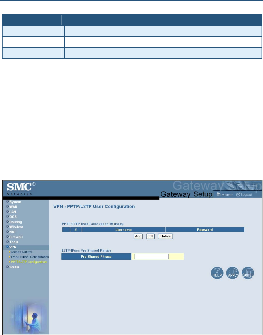
錯誤! 尚未定義樣式。
160
SMCD3GN2 Wireless Cable Modem Gateway Administrator Manual
Option Description
IP type IP Subnet.
IP Address IP address of the remote endpoint.
Subnet Mask Subnet mask of the remote endpoint.
Using the VPN Log
VPN log information appears below the tunnel table on the VPN – Tunnel Configuration
menu. Buttons below the log let you clear or refresh (update) the log information displayed,
or send the logs to a drive location. Before you can send the logs to a drive location, enable
email and syslog notification on the Email/Syslog Alert menu (see page 125).
Using the VPN – PPTP / L2TP User Configuration Menu
Using the VPN – PPTP / L2TP User Configuration menu, you can set up to 50 PPTP / L2TP
user accounts and define a pre-shared phrase. To access the VPN – PPTP / L2TP User
Configuration menu, click VPN in the menu bar and then click the PPTP/L2TP
Configuration submenu. Figure 87 shows an example of the menu.
Figure 87. VPN – PPTP / L2TP User Configuration Menu
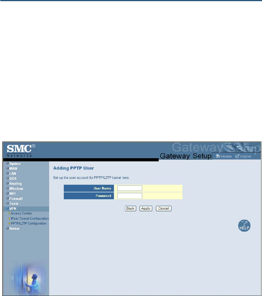
錯誤! 尚未定義樣式。
161
SMCD3GN2 Wireless Cable Modem Gateway Administrator Manual
Defining PPTP / L2TP Users
Using the following procedure, you can add up to 50 PPTP / L2TP users.
1. Click VPN in the menu bar.
2. On the VPN menu, uncheck one of the following options and click Apply (see Figure 83).
Otherwise, the buttons for adding, editing, and deleting the VPN – PPTP / L2TP
configurations on the VPN – PPTP / L2TP User Configuration menu will be unavailable.
– Disable PPTP VPN Functions
– Disable L2TP over IPsec VPN Functions
3. In the menu bar, under VPN, click the PPTP/L2TP Configuration submenu.
4. In the VPN – PPTP / L2TP User Configuration menu, click the Add button. The Adding
PPTP User menu in Figure 88 appears.
Figure 88. Adding PPTP User Menu
5. Complete the fields in the Adding PPTP User menu (see Table 35).
6. Click Apply to add the PPTP user. (Or click Back to return to the previous menu or Cancel
to cancel the operation.) If you clicked Apply, the PPTP user is added to the PPTP/L2TP
User Table.
7. To add more PPTP users (up to 50), repeat steps 4 through 6.
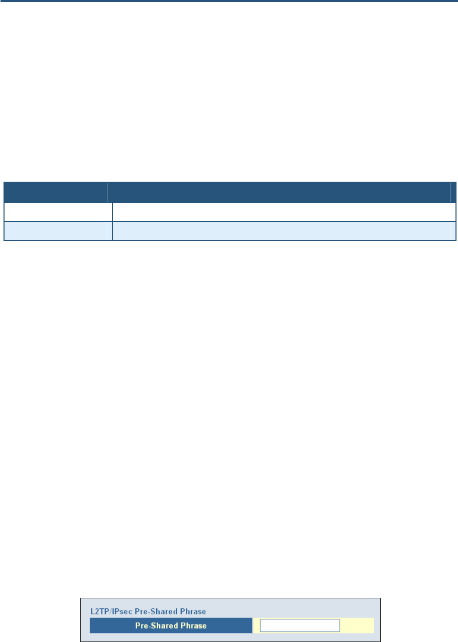
錯誤! 尚未定義樣式。
162
SMCD3GN2 Wireless Cable Modem Gateway Administrator Manual
8. To change the settings for a PPTP user, click the radio button to the left of the PPTP user
you want to change and click the Edit button. When the Adding PPTP User menu appears,
edit the settings (see Table 35) and click Apply. Click Apply in the VPN – PPTP / L2TP
User Configuration menu to save your settings.
9. To delete a PPTP user, click the radio button to the left of the PPTP user you want to
delete and click the Delete button. No precautionary message appears before you delete a
PPTP user. Click Apply in the VPN – PPTP / L2TP User Configuration menu to save your
settings.
Table 35. Adding PPTP User Menu Options
Option Description
User Name Username used to authenticate the PPTP/L2TP user.
Password Password used to authenticate the PPTP/L2TP user.
Defining L2TP / IPSec pre-shared Phrase
The configuration of L2TP with IPSec requires that all VPN clients and gateways use the
same pre-shared key (or “phrase”). If the pre-shared phrase is changed because it has been
compromised, you must manually change the phrase on each device that uses a pre-shared
phrase to connect to the VPN gateway. A pre-shared phrase can be up to 256 characters.
The longer and more complex the phrase, the harder it is to guess.
Using the VPN – PPTP / L2TP User Configuration menu, you can define the pre-shared
phrase that the Gateway uses.
1. Click VPN in the menu bar.
2. On the VPN menu, uncheck one of the following options and click Apply (see Figure 83).
Otherwise, the buttons for adding, editing, and deleting the VPN – PPTP / L2TP
configurations on the VPN – PPTP / L2TP User Configuration menu will be unavailable.
– Disable PPTP VPN Functions
– Disable L2TP over IPsec VPN Functions
3. In the menu bar, under VPN, click the PPTP/L2TP Configuration submenu.
4. In the VPN – PPTP/L2TP User Configuration menu, under L2TP/IPsec Pre-Shared
Phrase, enter the pre-shared phrase in the Pre-Shared Phrase field (see Figure 89).
5. Click the Apply button.
Figure 89. Pre-Shared Phrase Field

錯誤! 尚未定義樣式。
163
SMCD3GN2 Wireless Cable Modem Gateway Administrator Manual
Viewing Status Information
The Status page is a read-only screen that shows the:
y Connection status for the Gateway’s WAN and LAN interfaces
y Firmware and hardware versions
y Any illegal attempts to access your network
y Information about all DHCP clients currently connected to the Gateway
y Network and cable modem system event logs, with buttons for clearing, refreshing, or
sending the logs to a drive location (before you can send the logs to a drive location,
enable email and syslog notification on the Email/Syslog Alert menu - see page 125)
y LAN client log, with buttons for refreshing and releasing IP addresses
The Status menu appears when you first log in to the Web management interface. You
can also display it by clicking Status in the menu bar.
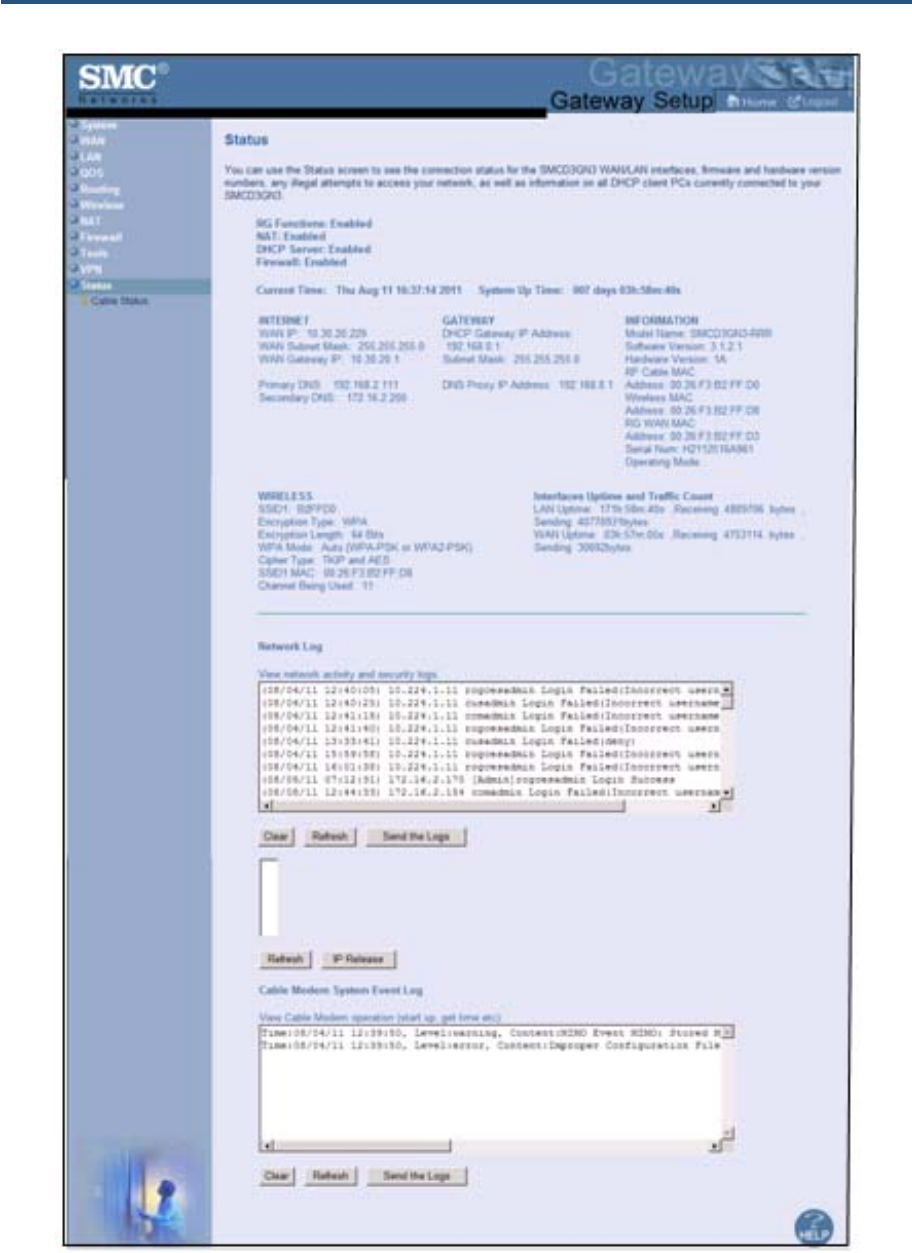
錯誤! 尚未定義樣式。
164
SMCD3GN2 Wireless Cable Modem Gateway Administrator Manual
Figure 90 shows an example of the status information shown.

錯誤! 尚未定義樣式。
165
SMCD3GN2 Wireless Cable Modem Gateway Administrator Manual

錯誤! 尚未定義樣式。
166
SMCD3GN2 Wireless Cable Modem Gateway Administrator Manual
Figure 90. Example of Status Page

錯誤! 尚未定義樣式。
167
SMCD3GN2 Wireless Cable Modem Gateway Administrator Manual
Viewing Cable Status Information
The Cable Status page is a read-only screen that shows the user’s cable initialization
procedures, along with the cable upstream and downstream status.
The Cable Status menu appears when you first log in to the Web management
interface. You can also display it by clicking Status in the menu bar and
then clicking the Cable Status submenu.
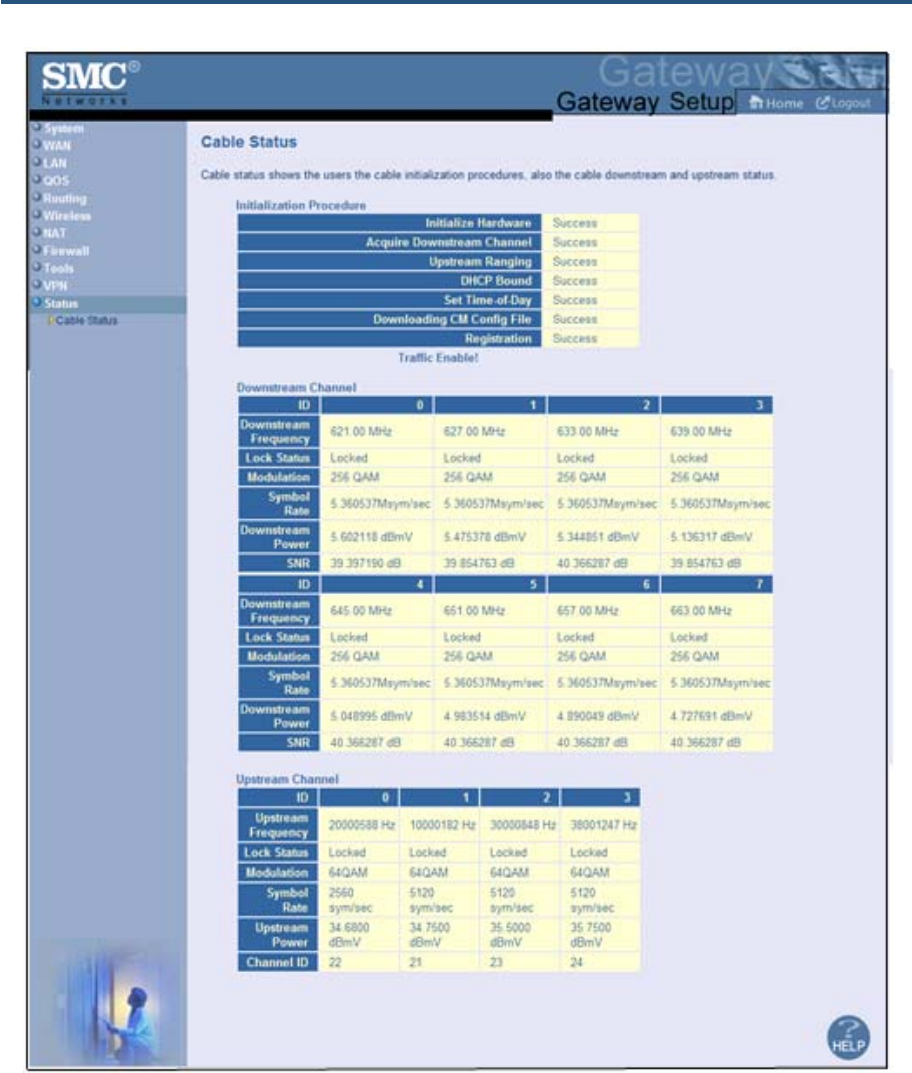
錯誤! 尚未定義樣式。
168
SMCD3GN2 Wireless Cable Modem Gateway Administrator Manual
Figure 91 shows an example of the cable status information shown.
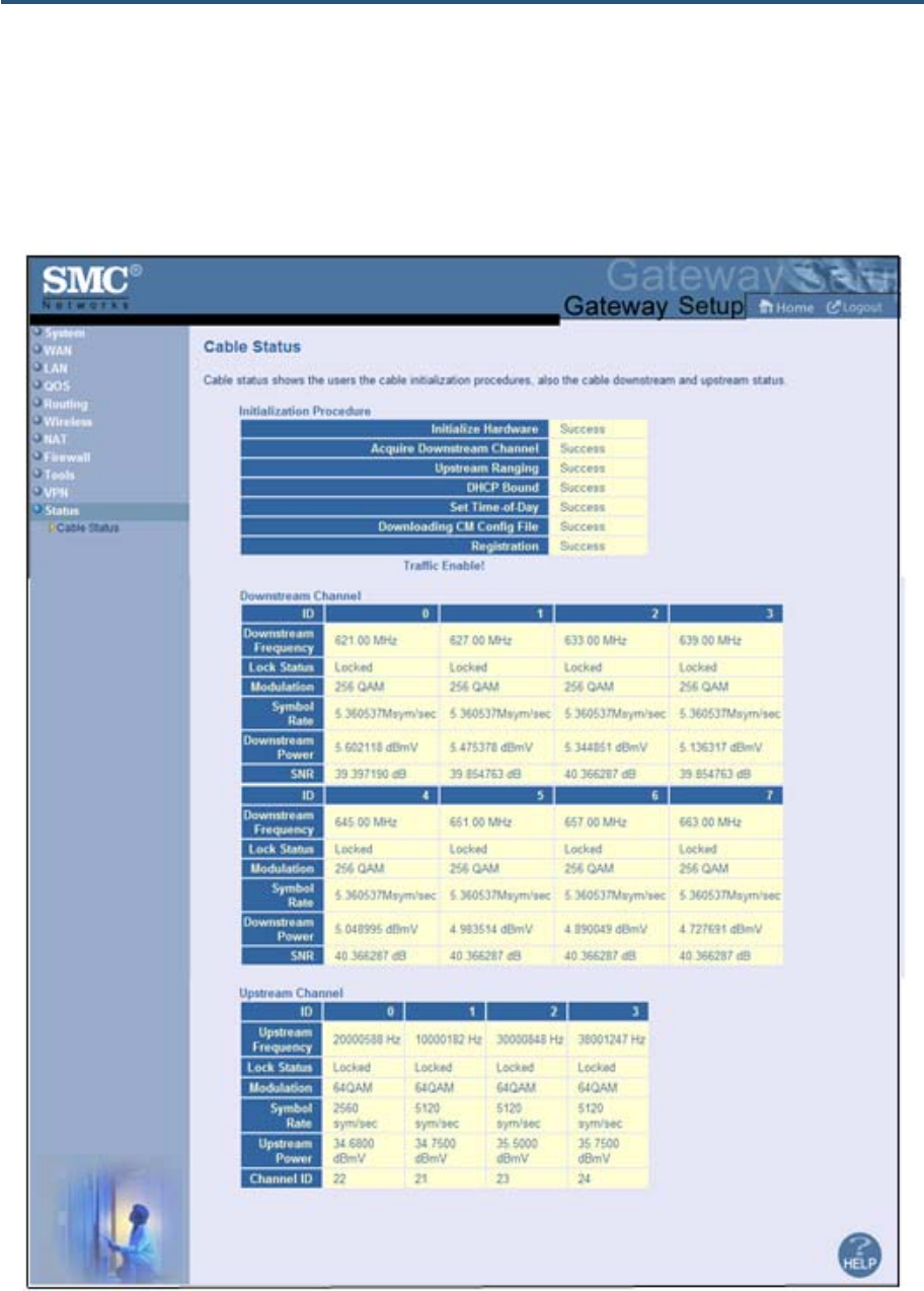
錯誤! 尚未定義樣式。
169
SMCD3GN2 Wireless Cable Modem Gateway Administrator Manual
Figure 91. Example of Cable Status Page

170
SMCD3GN2 Wireless Cable Modem Gateway Administrator Manual
Appendix A - Compliances
FCC Interference Statement
This equipment has been tested and found to comply with the limits for a Class B digital device pursuant to Part
15 of the FCC Rules. These limits are designed to provide reasonable protection against radio interference in a
commercial environment. This equipment can generate, use and radiate radio frequency energy and, if not
installed and used in accordance with the instructions in this manual, may cause harmful interference to radio
communications. Operation of this equipment in a residential area is likely to cause interference, in which case
the user, at his own expense, will be required to take whatever measures are necessary to correct the
interference. If this equipment does cause harmful interference to radio or television reception, which can be
determined by turning the equipment off and on, the user is encouraged to try to correct the interference by one
of the following measures:
y Reorient or relocate the receiving antenna.
y Increase the separation between the equipment and receiver.
y Connect the equipment into an outlet on a circuit different from that to which the receiver is connected.
y Consult the dealer or an experienced radio/TV technician for help.
The device complies with Part 15 of the FCC Rules. Operation is subject to the following two conditions: (1) This
device may not cause harmful interference, and (2) this device must accept any interference received, including
interference that may cause undesired operation.
FCC Caution: Any changes or modifications not expressly approved by the party responsible for compliance
could void the user’s authority to operate this equipment.
IEEE 802.11b or 802.11g operation of this product in the U.S.A is firmware-limited to channels 1 through 11.
IMPORTANT NOTE:
FCC Radiation Exposure Statement:
This equipment complies with FCC radiation exposure limits set forth for an uncontrolled environment. This
equipment should be installed and operated with minimum distance 20cm between the radiator & your body.
This transmitter must not be co-located or operating in conjunction with any other antenna or transmitter.
The availability of some specific channels and/or operational frequency bands are country dependent and are
firmware programmed at the factory to match the intended destination. The firmware setting is not accessible by
the end user.
Note to CATV System Installer - The cable distribution system should be grounded (earthed) in accordance with
ANSI/NFPA 70, the National Electrical Code (NEC), in particular Section 820.93, Grounding of Outer Conductive
Shield of a Coaxial Cable.

171
SMCD3GN2 Wireless Cable Modem Gateway Administrator Manual
Index
1
1-to-1 Mapping menu, 98
A
Access control, 103
adding customer-defined access rule, 107
adding customer-defined filter, 112
adding predefined access rule, 104
adding predefined filter, 110
Access Control (VPN) menu, 143
Access Control menu, 103
Adding
customer-defined access rule for access control,
107
customer-defined filter for access control, 112
customer-defined service for port forwarding, 95
predefined access rule for access control, 104
predefined filter for access control, 110
predefined service for port forwarding, 93
Additional Public Lan menu, 55
Advanced Wireless Settings menu, 89
Alert options, 124
Alerts, 121
Apple Macintosh TCP/IP configuration, 26
Auto-negotiation, 50
B
Blocking
domain, 120
keyword, 119
C
Cable Status menu, 154
Changing login password, 38
Cipher type, 81
Computer exempted from URL blocking, 119
Configuration, 28
Configuring
access control, 103
alert options, 124
auto-negotiation, 50
DHCP, 48
duplex mode, 50
email alerts, 123
firewall, 101
idle timeout, 38
login password, 38
port forwarding, 92
private LAN IP address, 48
special applications, 115
syslog entries, 124
TCP/IP, 19
wireless security, 14
Connecting
LAN, 17
WAN, 18
Conventions in this document, viii
CoS Settings menu, 62
Customer UI Setup menu, 43
Customer-defined
service for port forwarding, 95
service table, 92
Customer-defined access rule, 107
Customer-defined filter, 112
D
DHCP setting, 48
Diagnostics menu, 134
Disabling
firewall, 30

Index
172
SMCD3GN2 Wireless Cable Modem Gateway Administrator Manual
LAN ports, 50
security software, 30
VPN, 141
Disabling proxy settings
Firefox, 29
Internet Explorer, 29
Safari, 30
DMZ (Demilitarized Zone) menu, 125
Document
conventions, viii
organization, viii
Domain blocking, 120
DSCP Based QoS menu, 64
DSCP Remarking menu, 68
Duplex mode, 50
E
Email alerts, 121, 123
Email/Syslog Alert menu, 121
Enabling
VPN, 141
Enabling LAN ports, 50
Ether Switch Port Control menu, 50
Exempted computers, 119
F
Factory defaults
restoring, 15
Firefox, disabling proxy settings, 29
Firewall
configuring, 101
disabling, 30
Front panel, 12
LEDs, 13
G
Gateway
configuring, 28
connecting to the LAN, 17
connecting to the WAN, 18
front panel, 12
installing, 16
key features, vii
LEDs, 13
locating, 17
package contents, 11
powering on, 18
preconfiguring, 29
rear panel, 14
rebooting and losing custom settings, 15, 132
system requirements, 11
Web management, 31
I
Idle timeout, 38
Ignoring pings, 114
Installation, 16
Internet Explorer, disabling proxy settings, 29
K
Key features, vii
Keyword blocking, 119
L
LAN Access Control menu, 51
LAN connection, 17
LAN ports, enabling or disabling, 50
LAN Settings menu, 48
Lease time, 48
LEDs, 13
Locating the Gateway, 17
Logging in to Web management, 31
Login password, 38
M
MAC Spoofing menu, 47
Menus
1-to-1 Mapping, 98
Access Control, 103
Access Control (VPNs), 143
Additional Public Lan, 55
Advanced Wirerless Settings, 89

Index
173
SMCD3GN2 Wireless Cable Modem Gateway Administrator Manual
Cable Status, 154
CoS Settings, 62
Customer UI Setup, 43
Diagnostics, 134
DMZ (Demilitarized Zone), 125
DSCP Based QoS, 64
DSCP Remarking, 68
Email/Syslog Alerts, 121
Ether Switch Port Control, 50
LAN Access Control, 51
LAN Settings, 48
MAC Spoofing, 47
NAT Settings, 91
OSPF Control, 75
Password Settings, 38
Port Based QoS, 61
Port Forwarding, 92
Public IP Access Control, 57
QoS Settings, 59
Queue Settings, 66
Reboot, 132
Remote Management, 42
RIP Control, 72
Routing, 70
Schedule Rules, 120
Security Settings (Firewall), 101
SNTP Settings, 140
Special Application, 115
Static Routes, 70
Status, 152
System Settings, 36
Trigger, 116
URL Blocking, 118
VPN, 141
VPN – PPTP / L2TP User Configuration, 149
VPN – Tunnel Configuration, 144
WAN Settings, 45
Wireless Basic Settings, 79
Wireless Encryption Settings, 81
WPS Setup, 84
Microsoft
TCP/IP configuration for Windows 2000, 20
TCP/IP configuration for Windows 7, 24
TCP/IP configuration for Windows Vista, 22
TCP/IP configuration for Windows XP, 21
N
NAT Settings menu, 91
O
OSPF, 75
P
Package contents, 11
Password Settings menu, 38
Password, changing, 38
Ping, 134
Pings, responding to or ignoring, 114
Port Based QoS menu, 61
Port forwarding
adding customer-defined service, 95
adding predefined service, 93
Port Forwarding menu, 92
Port triggering, 116
Powering-on the Gateway, 18
Preconfiguration guidelines, 29
Predefined
service for adding port forwarding, 93
service table, 92
Predefined access rule, 104
Predefined filter, 110
Private LAN IP settings
DHCP, 48
domain name, 48
IP address, 48
IP subnet mask, 48
lease time, 48
Proxy settings, 29
Public IP Access Control Lan menu, 57
Q
QoS Settings menu, 59
Queue Settings menu, 66

Index
174
SMCD3GN2 Wireless Cable Modem Gateway Administrator Manual
R
RADIUS configuration, 38
Rear panel, 14
Reboot menu, 132
Rebooting
losing custom settings, 15, 132
Remote Management menu, 42
Requirements, 11
Responding to pings, 114
Restoring factory defaults, 15
RIP, 72
Routing menu, 70
S
Safari, disabling proxy settings, 30
Schedule Rules menu, 120
Screens in Web management, 32
Security mode, 81
Security Settings (Firewall) menu, 101
Security software, 30
Security, configuring wireless, 14
Service table
customer-defined, 92
predefined, 92
SNTP Settings menu, 140
Special Application menu, 115
Spoofing MAC addresses, 47
SSID setting, 81
SSIDs, 79
Static Routes menu, 70
Status menu, 152
Syslog
alerts, 121
entries, 124
System requirements, 11
System Settings menu, 36
T
TACACS configuration, 38
TACACS+ configuration, 38
TCP/IP configuration, 19
Apple Macintosh, 26
Microsoft Windows 2000, 20
Microsoft Windows 7, 24
Microsoft Windows Vista, 22
Microsoft Windows XP, 21
Timeout for Web management session, 38
Trace route, 134
Trigger menu, 116
Triggering ports, 116
U
URL Blocking menu, 118
V
VPN – PPTP / L2TP User Configuration menu, 149
VPN – Tunnel Configuration menu, 144
VPN menu, 141
W
WAN connection, 18
WAN ping, 134
WAN Settings menu, 45
WAN trace route, 134
Web management
1-to-1 Mapping menu, 98
Access Control menu, 103
Access Control menu (VPNs), 143
Additional Public Lan menu, 55
Advanced Wireless Settings menu, 89
Cable Status menu, 154
CoS Settings, 62
Customer UI Setup menu, 43
Diagnostics menu, 134
DMZ (Demilitarized Zone) menu, 125
DSCP Based QoS, 64
DSCP Remarking, 68
Ether Switch Port Control menu, 50
LAN Access Control menu, 51
LAN Settings menu, 48
logging in, 31
MAC Spoofing menu, 47

Index
175
SMCD3GN2 Wireless Cable Modem Gateway Administrator Manual
NAT Settings menu, 91
OSPF Control menu, 75
Password Settings menu, 38
Port Based QoS, 61
Port Forwarding menu, 92
Public IP Access Control menu, 57
QoS Settings menu, 59
Queue Settings, 66
Reboot menu, 132
Remote Management menu, 42
RIP Control menu, 72
Routing menu, 70
Schedule Rules menu, 120
screens, 32
Security Settings (Firewall) menu, 101
SNTP Settings menu, 140
Special Application menu, 115
Static Routes menu, 70
Status menu, 152
System Settings menu, 36
Trigger menu, 116
URL Blocking menu, 118
URL Email/Syslog Alert menu, 121
VPN – PPTP / L2TP User Configuration menu,
149
VPN – Tunnel Configuration menu (VPNs), 144
VPN menu, 141
WAN Settings menu, 45
Wireless Basic Settings menu, 79
Wireless Encryption Settings menu, 81
WPS Setup menu, 84
Wireless
mode, 79
operation, 79
security, 14
Wireless Basic Settings menu, 79
Wireless Encryption Settings menu, 81
WPA mode, 81
WPS Setup menu, 84

20 Mason
Irvine, CA. 92618
U.S.A.
http://www.smc.com
Document number: 3121RRR081111