SMC Networks DORY3A Cable Gateway User Manual SMCD3GNV Wireless Cable Modem Gateway
SMC Networks Inc Cable Gateway SMCD3GNV Wireless Cable Modem Gateway
UserManual.wiki
>
SMC Networks
>
DORY3A User Manual
User manual
Navigation menu
Upload a User Manual
Namespaces
Wiki Guide
HTML
PDF
Info
Views
User Manual
Discussion / Help
Navigation
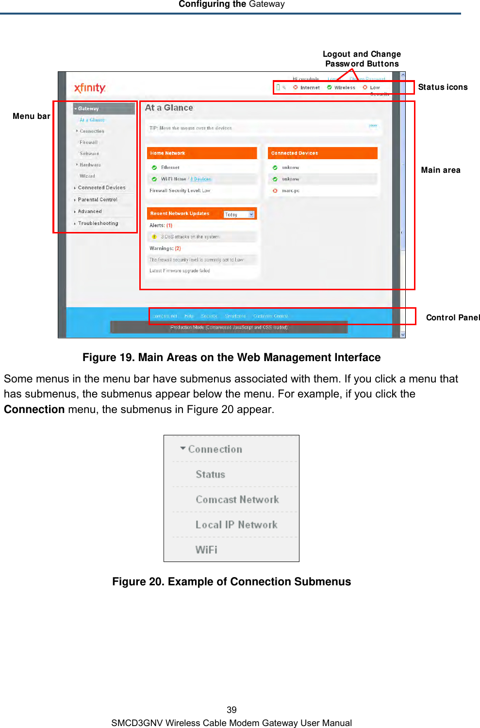
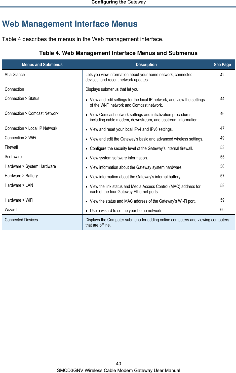
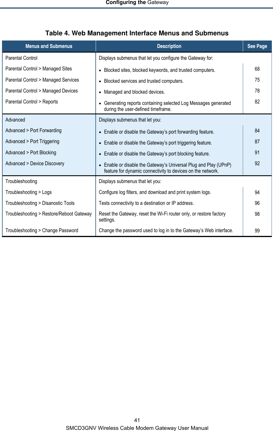
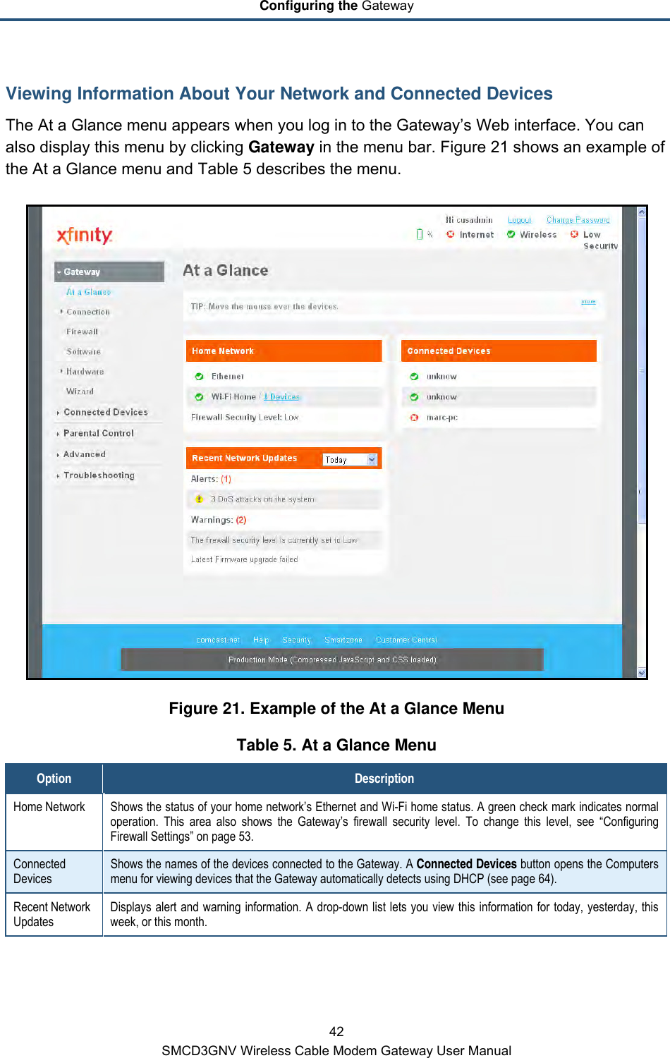
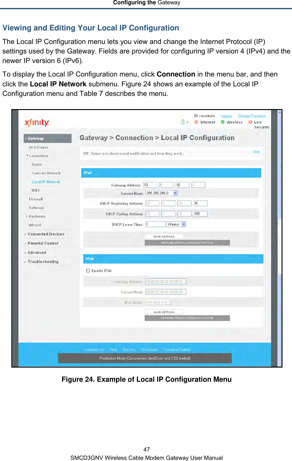
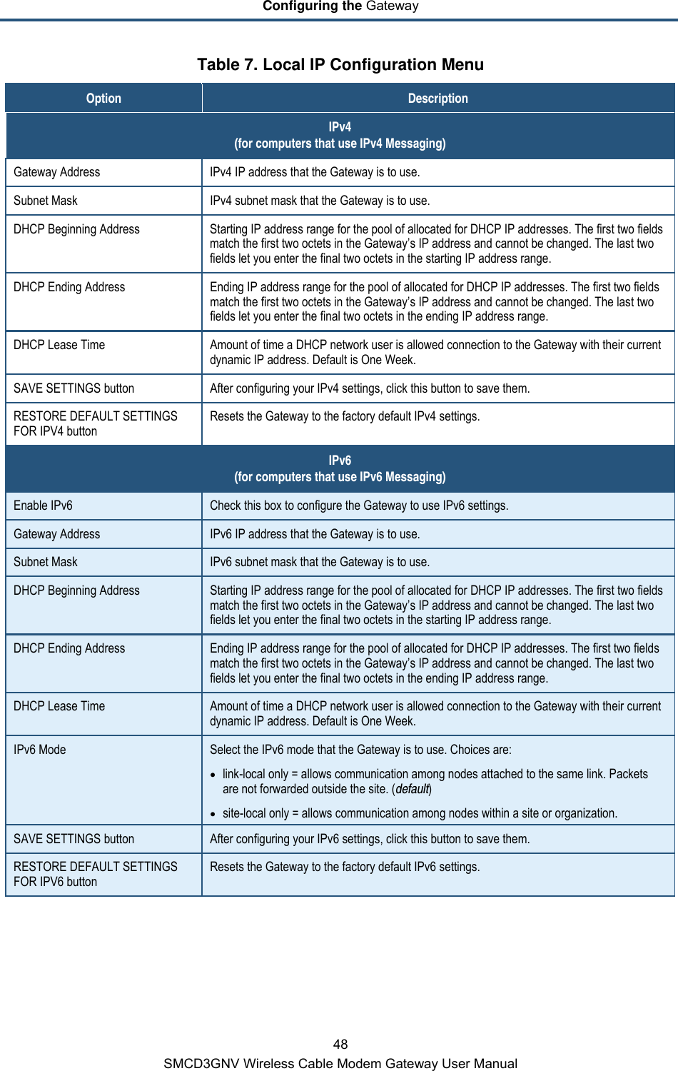
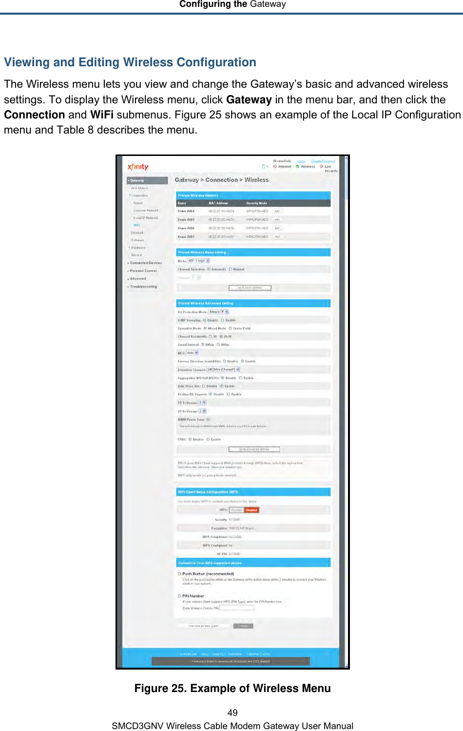
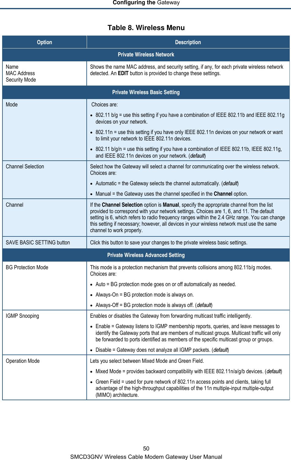
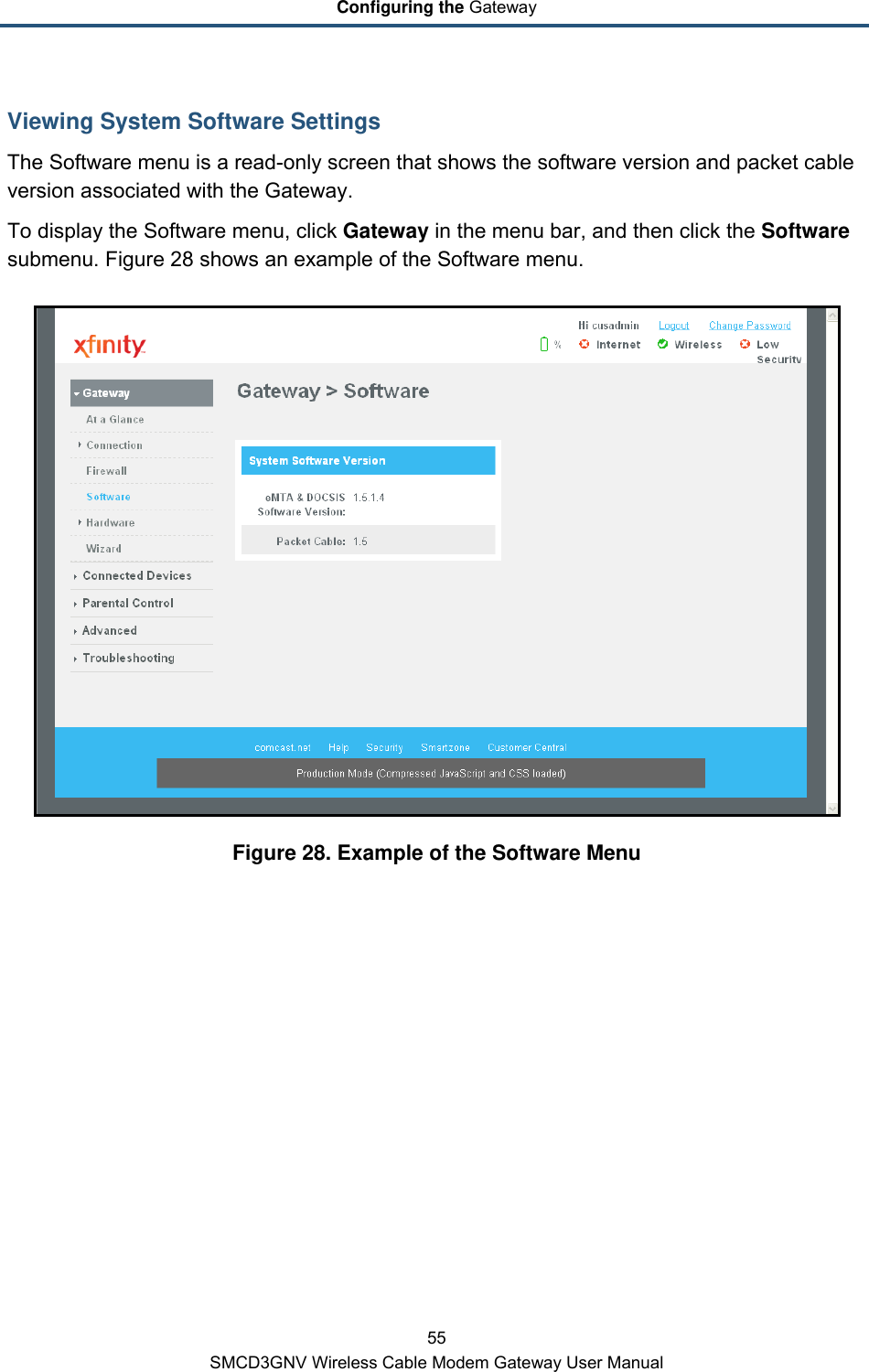
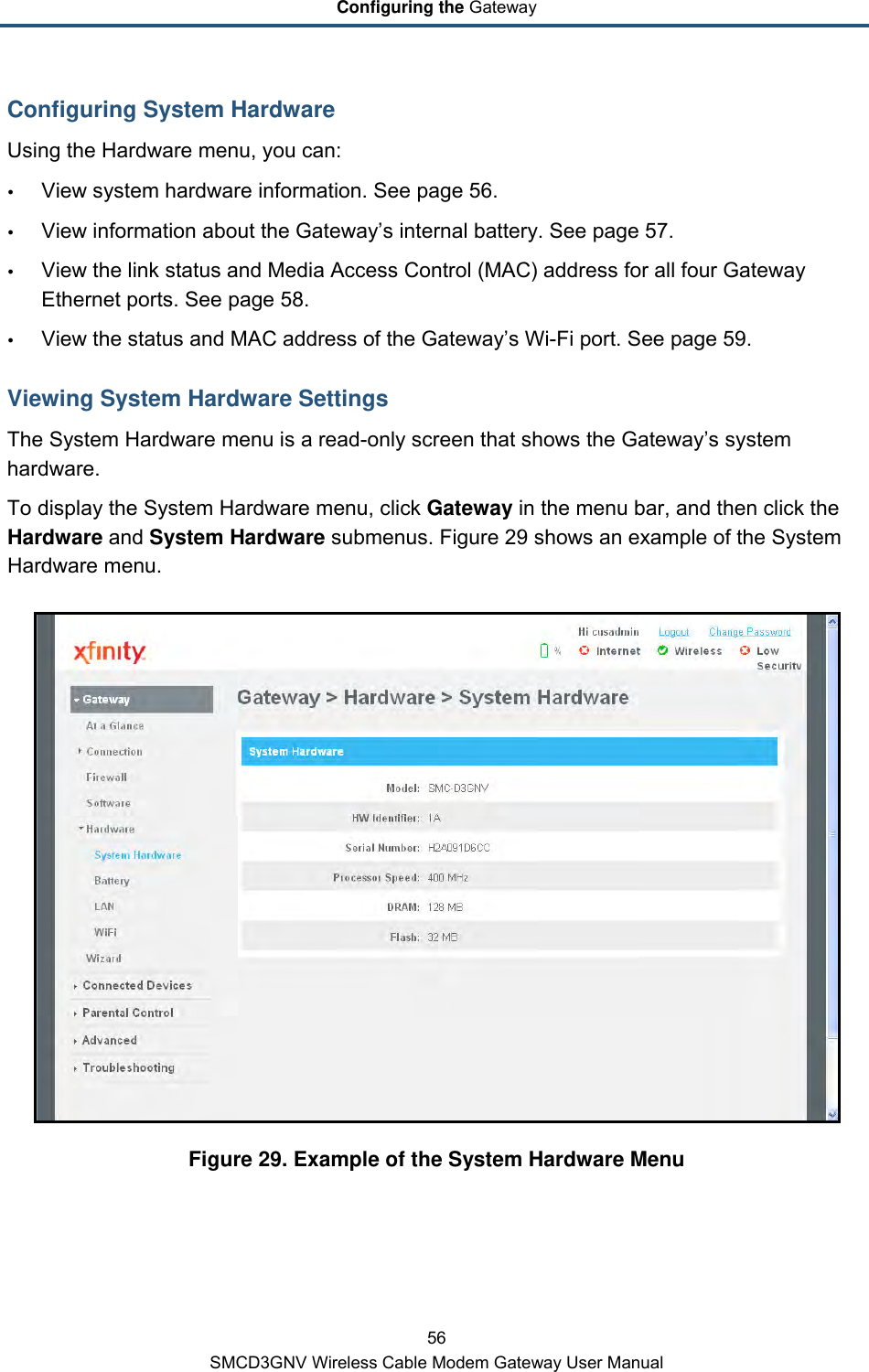
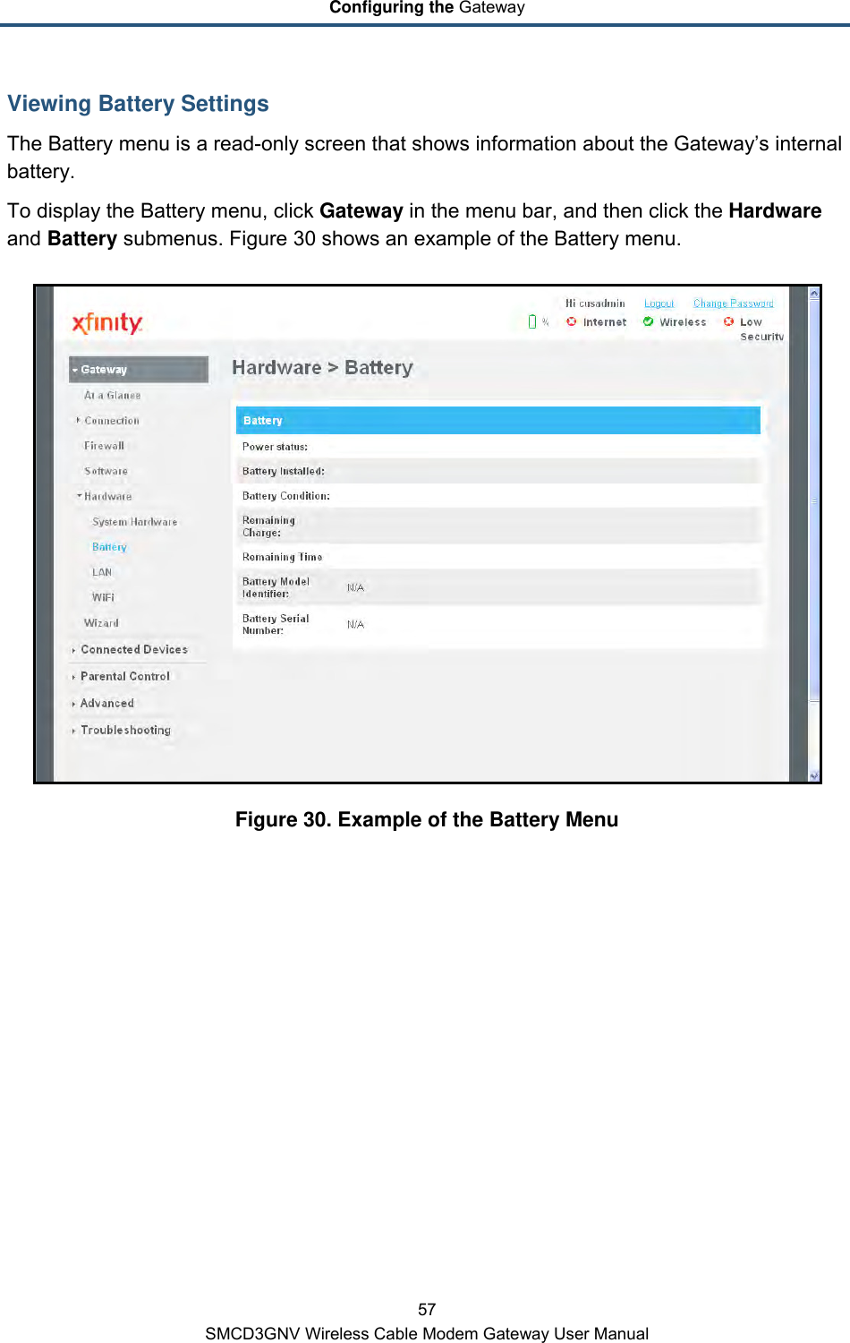
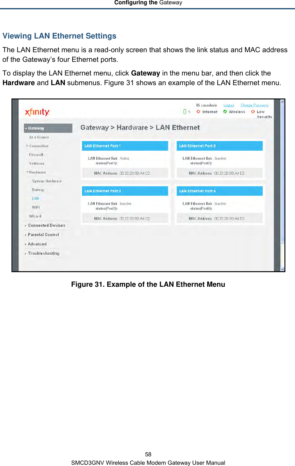
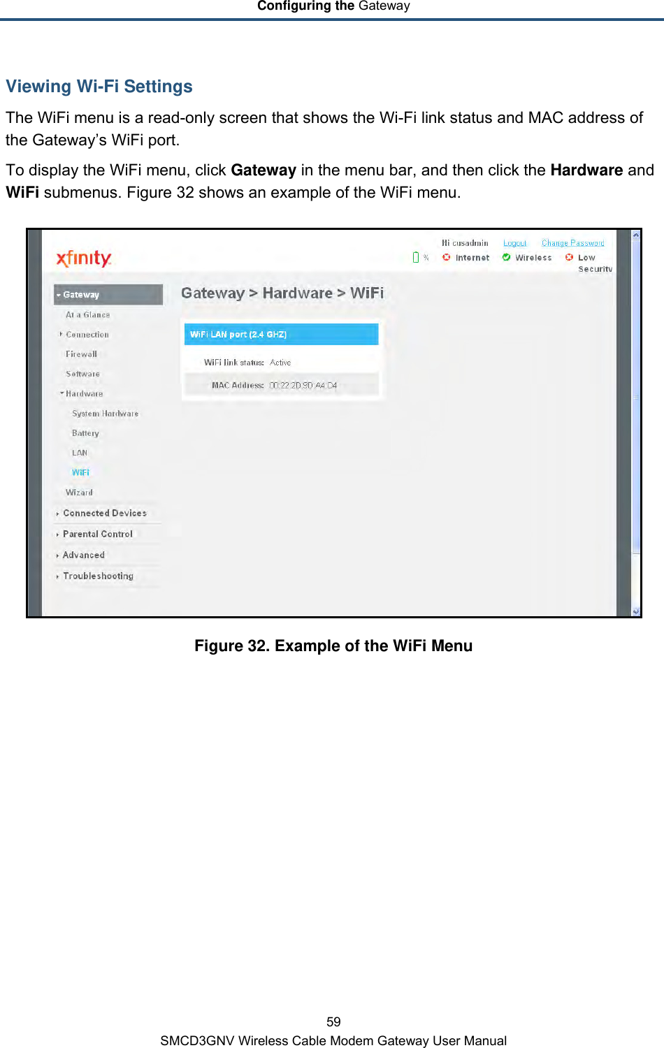
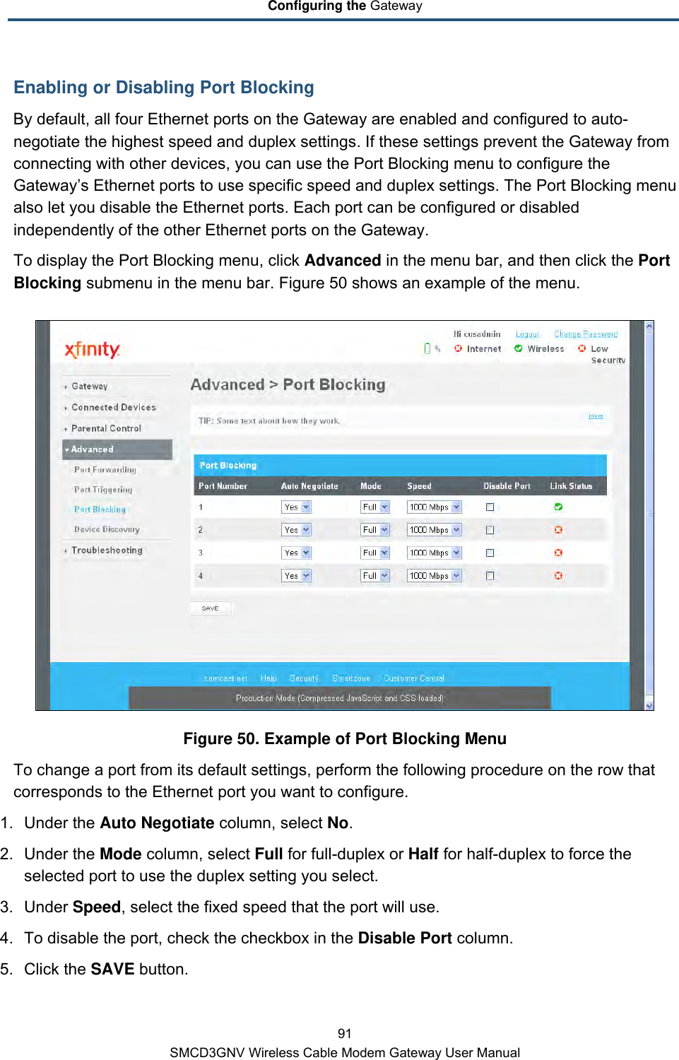
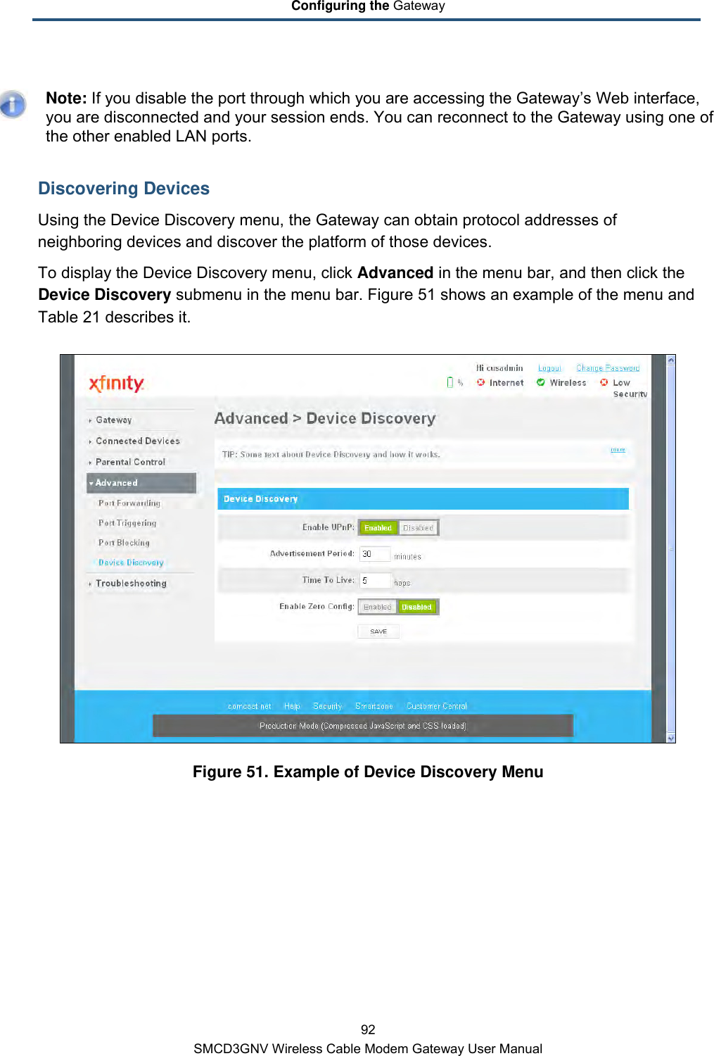
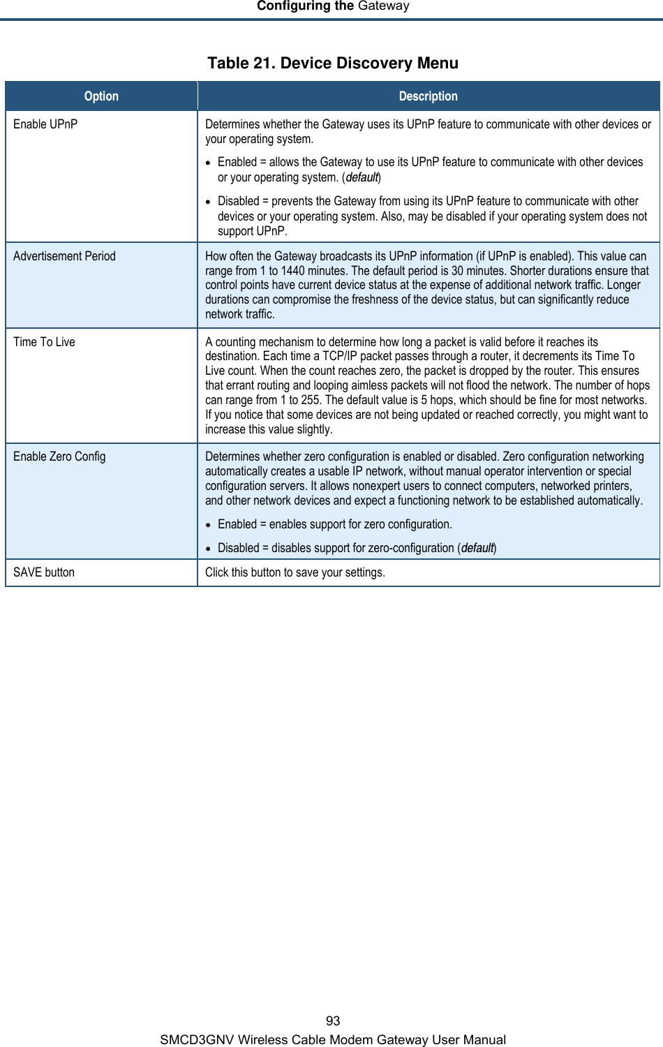
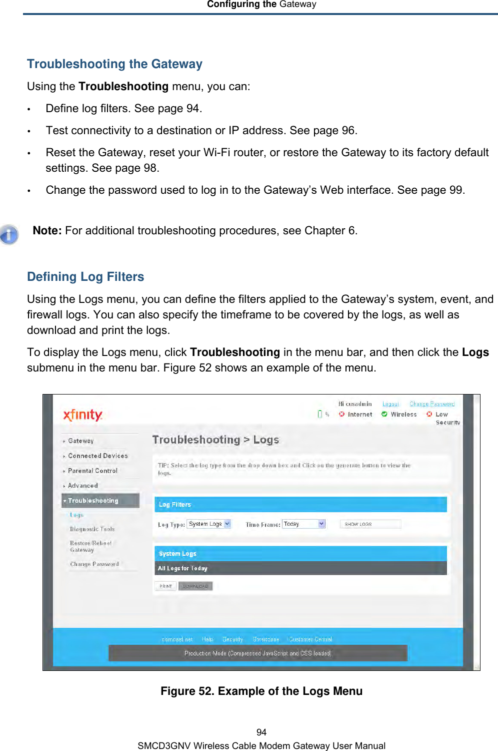
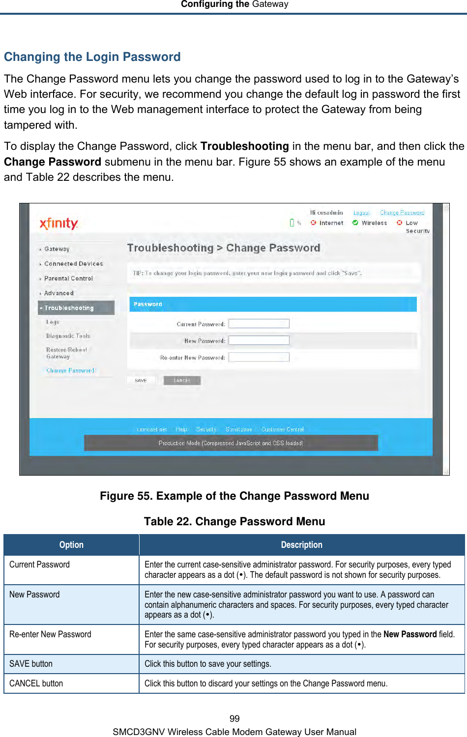
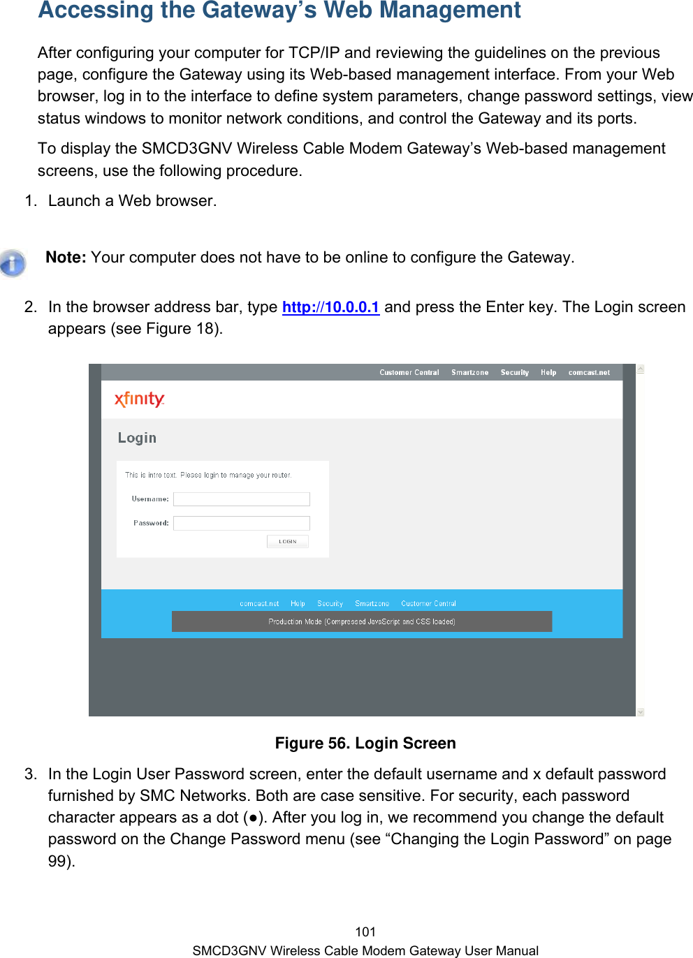
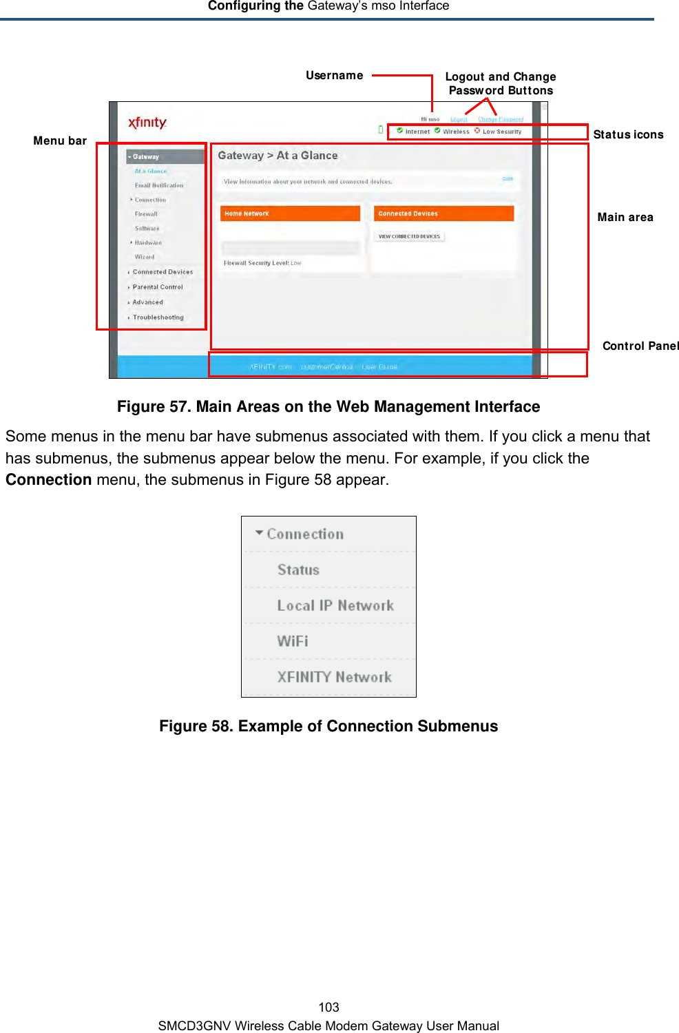
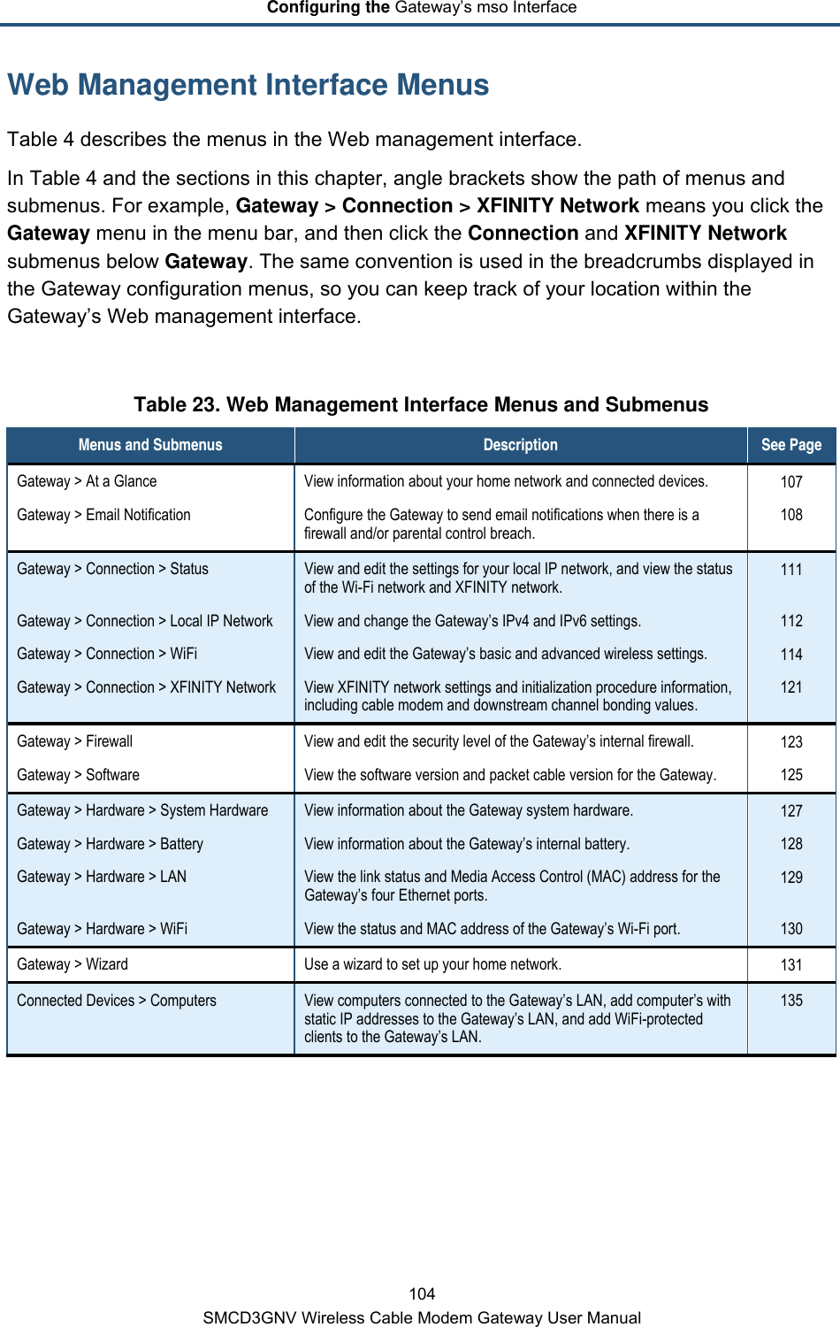
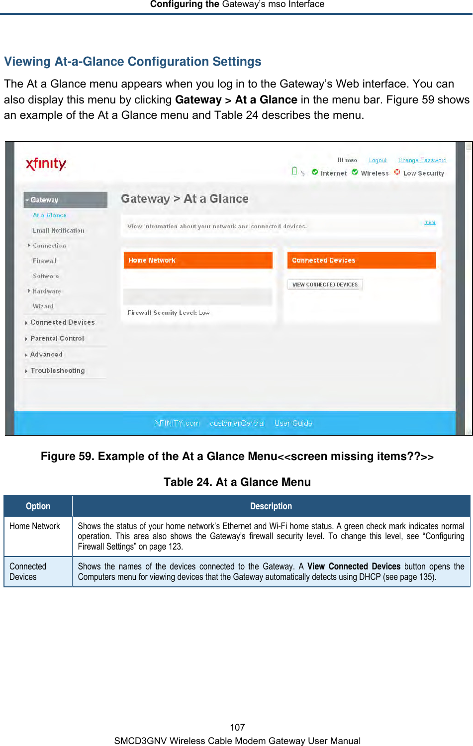
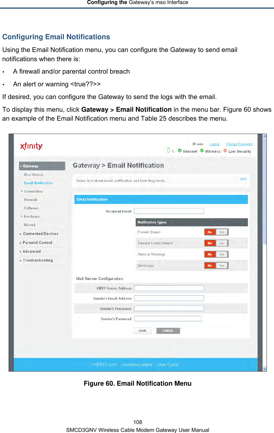
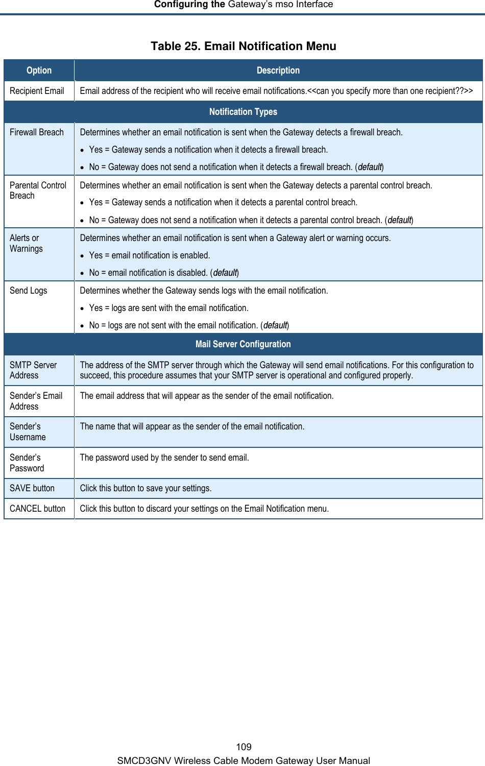
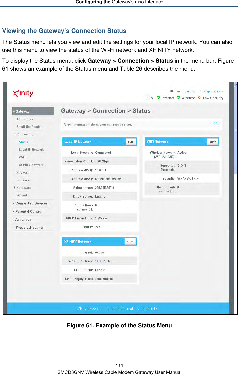
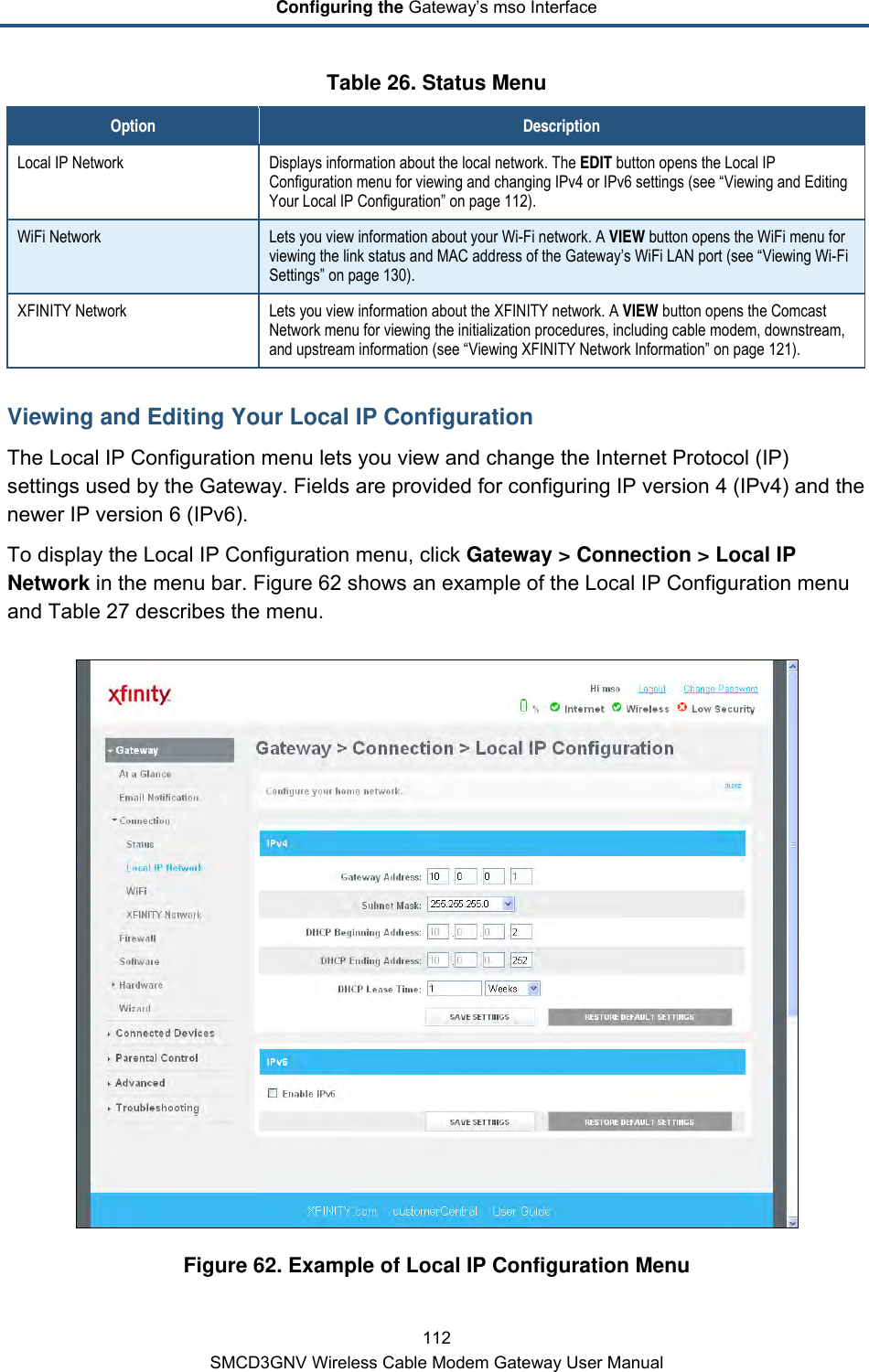
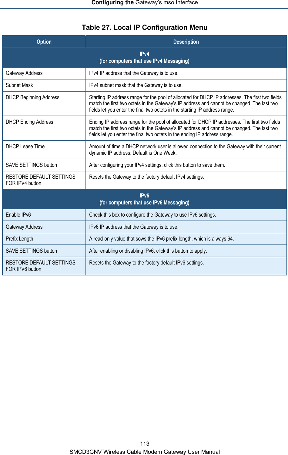
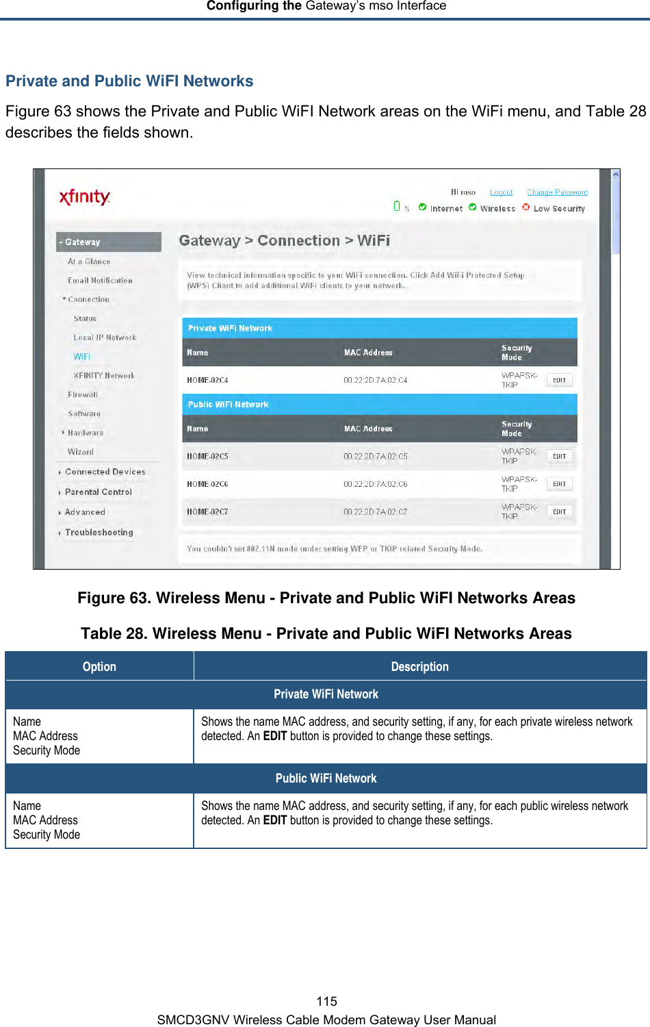
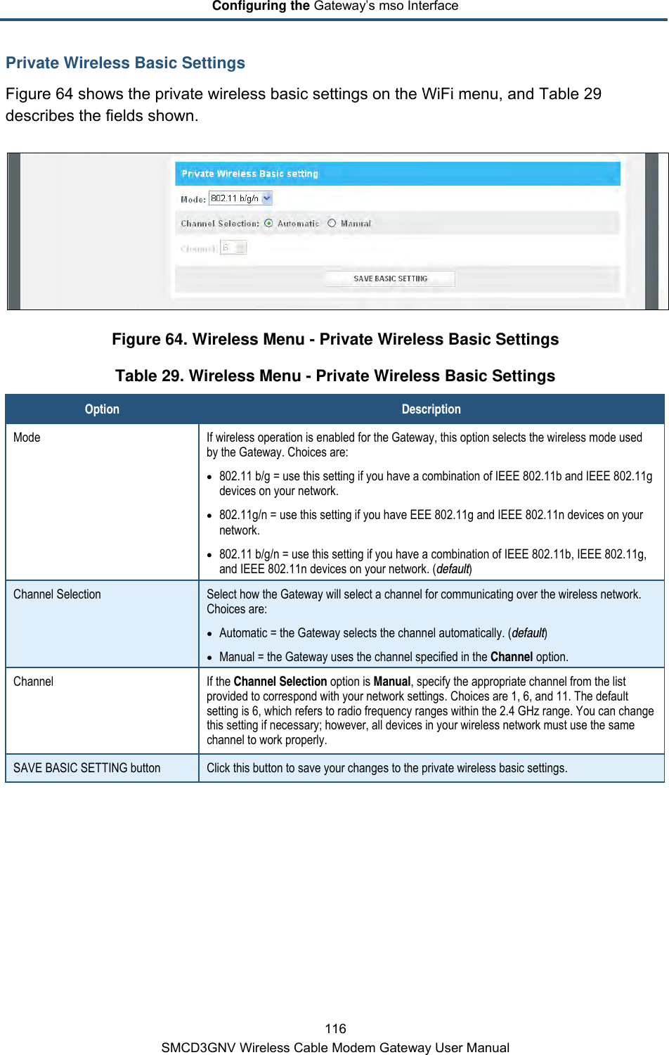
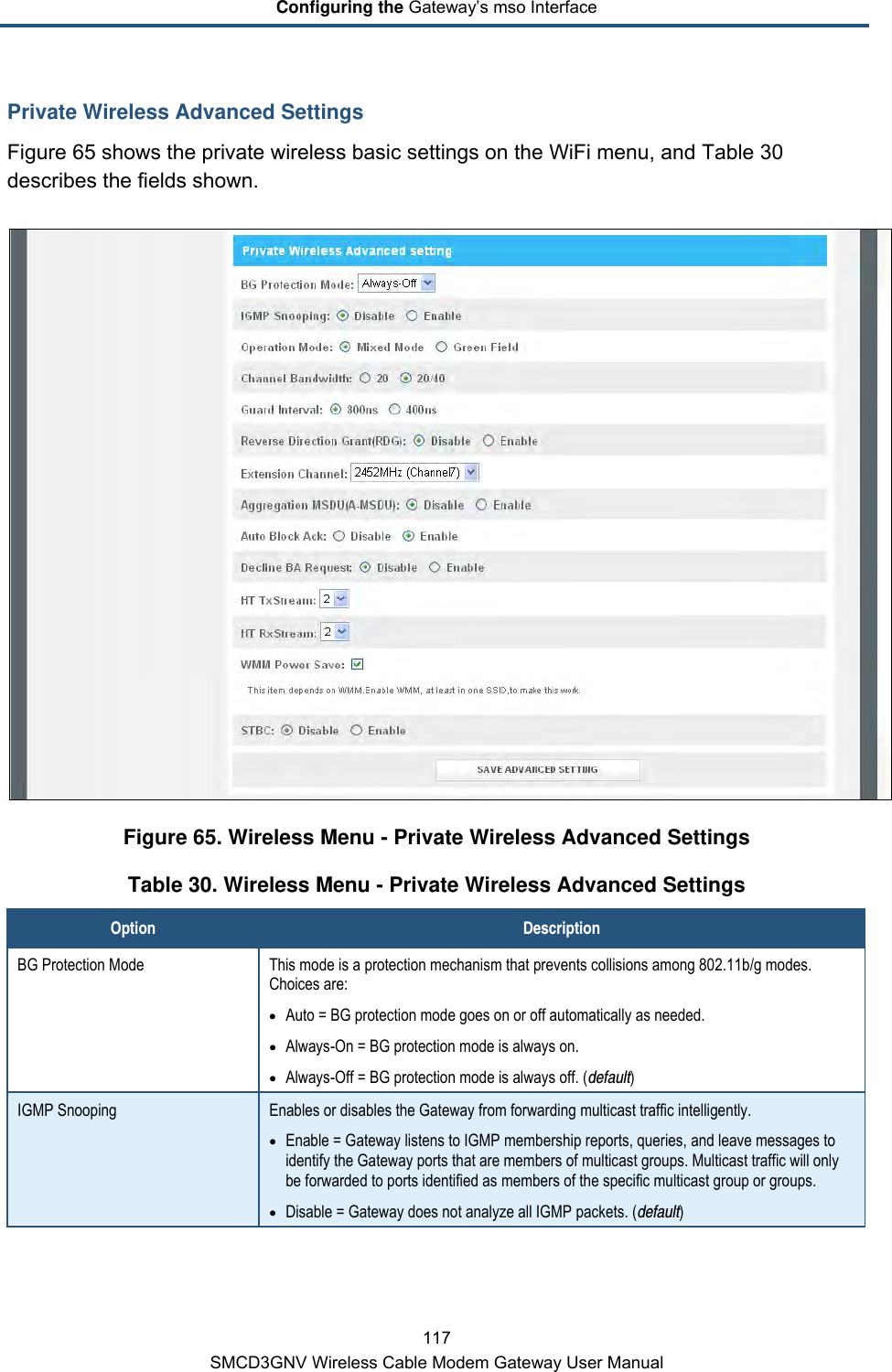
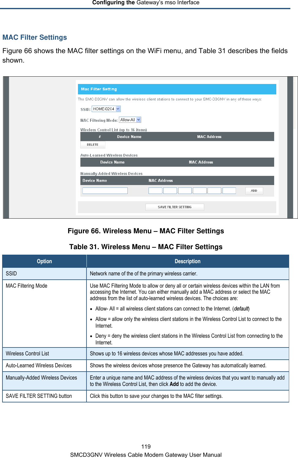
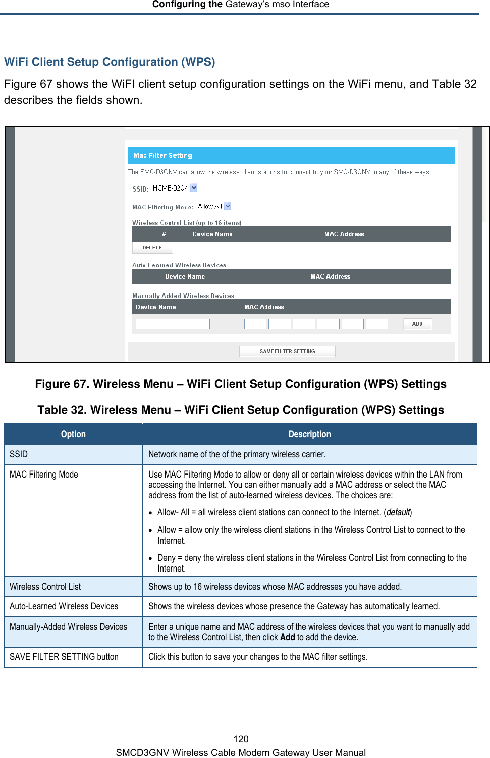
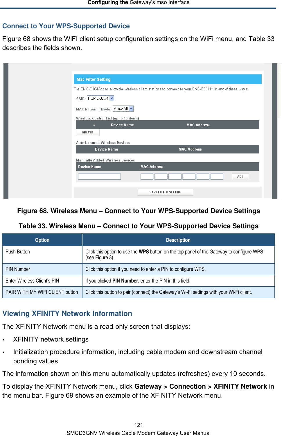
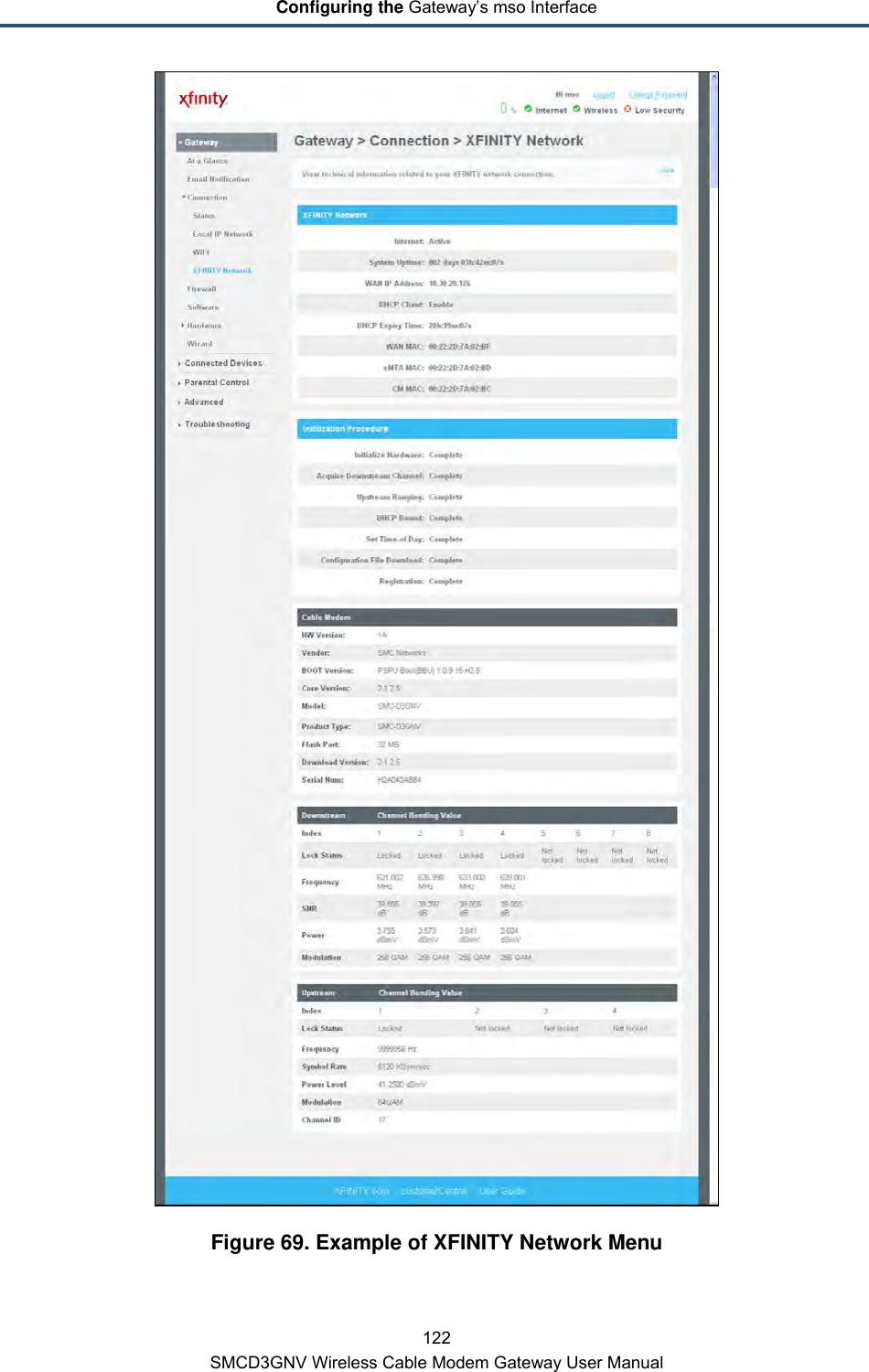
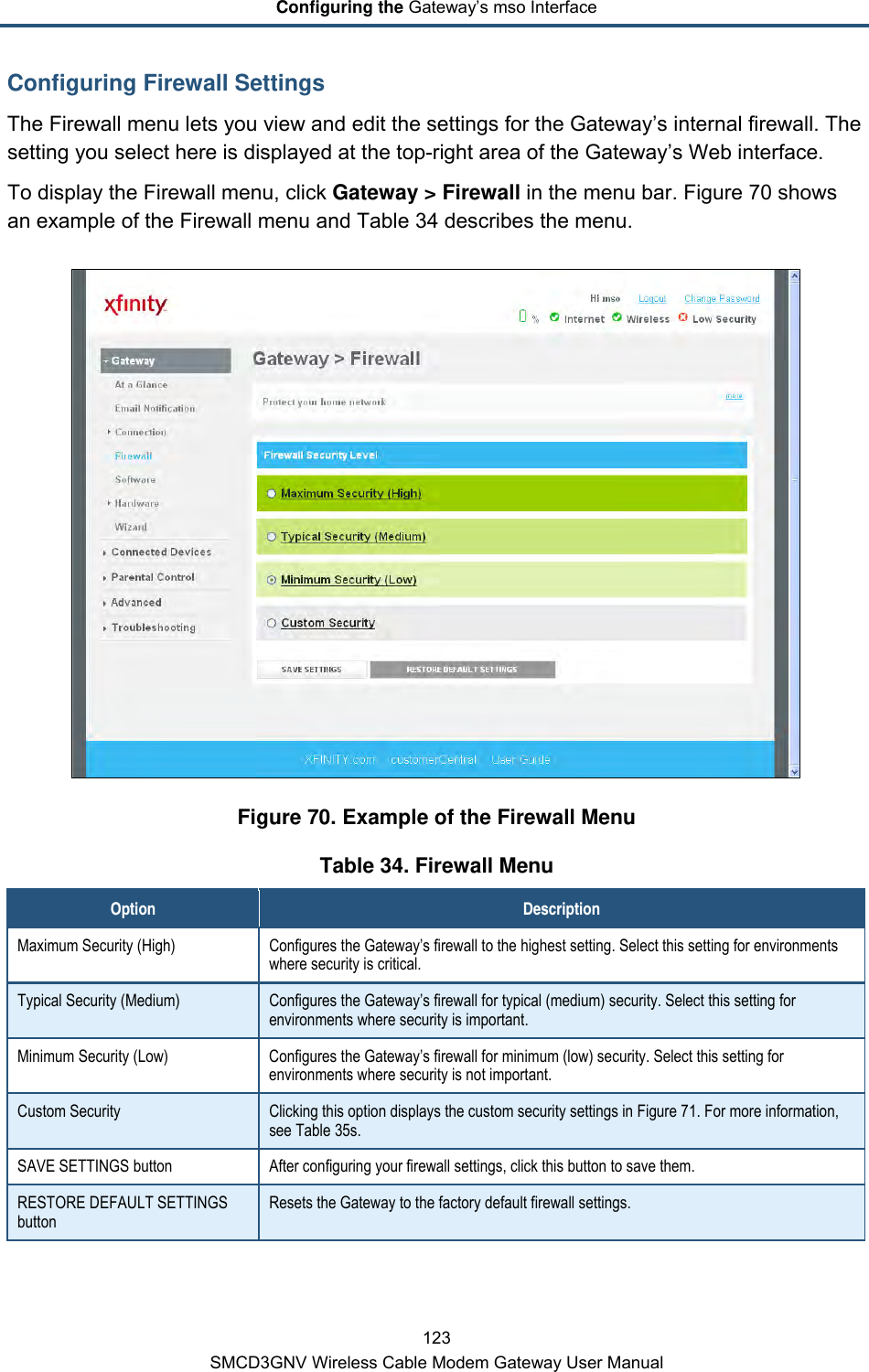
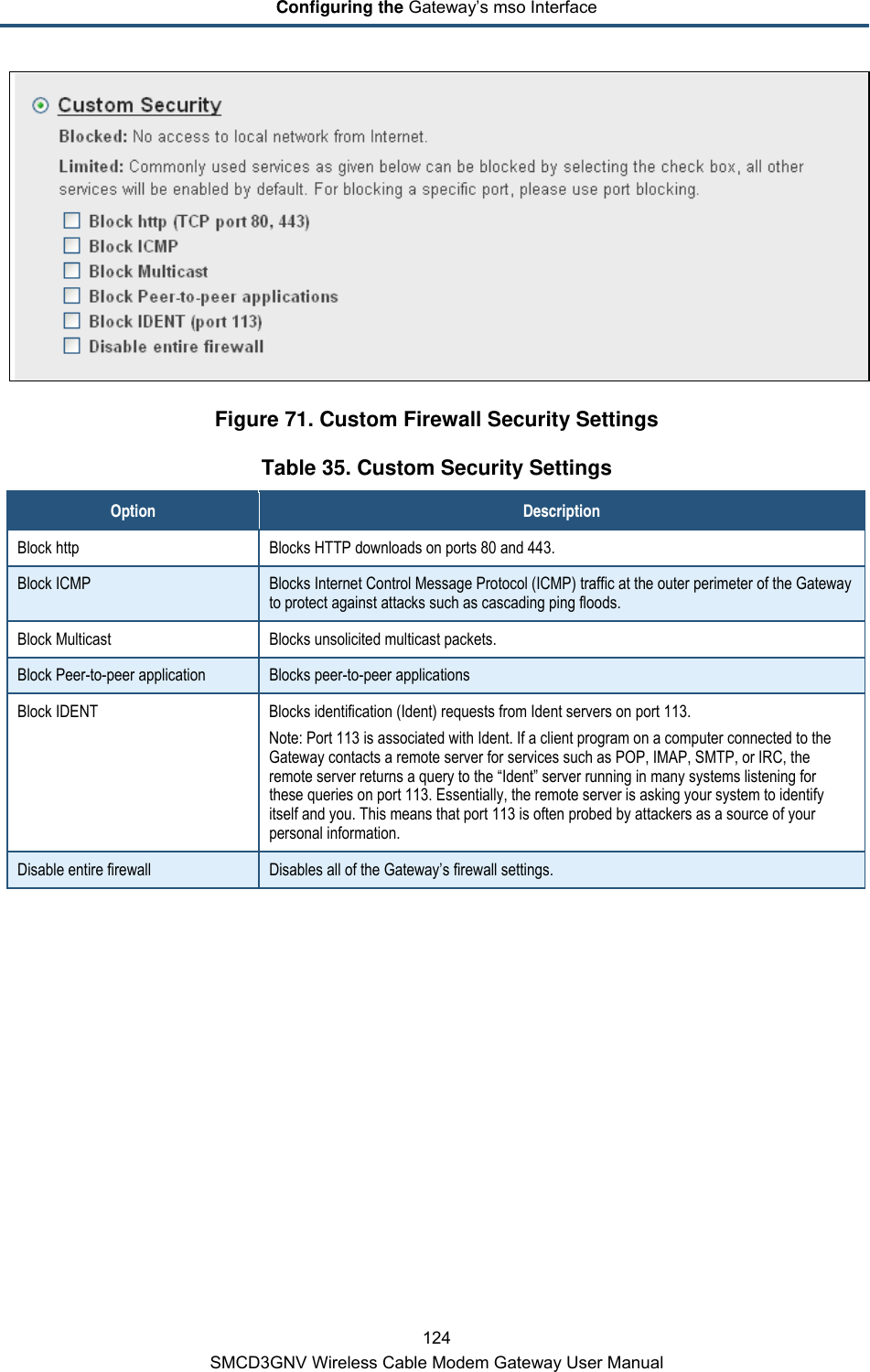
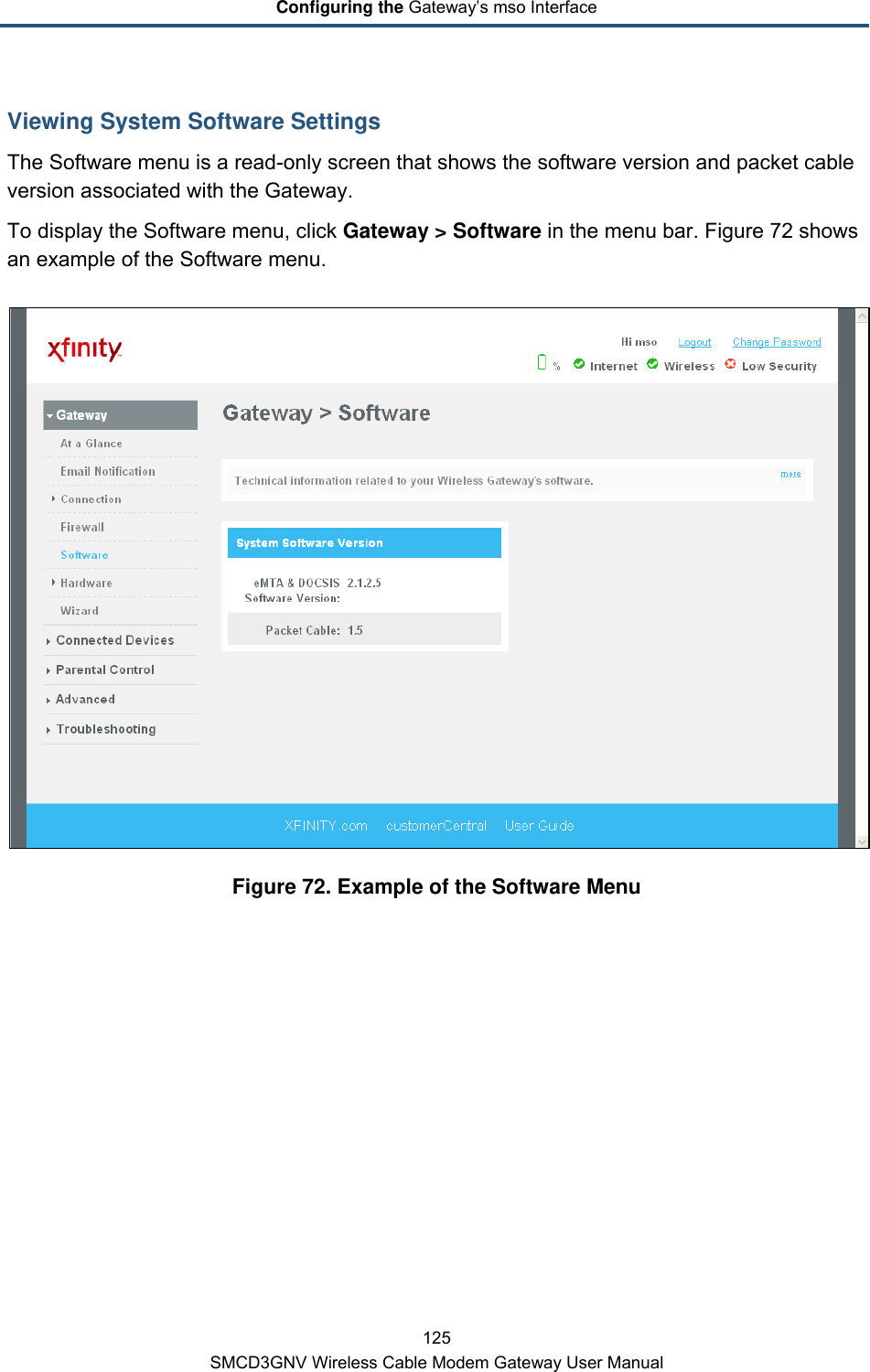
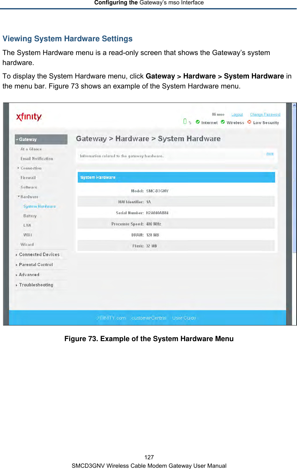
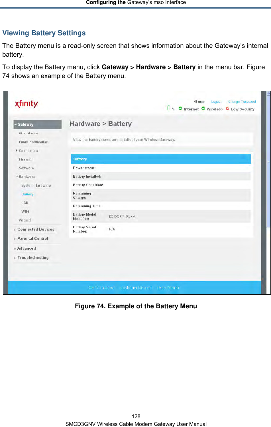
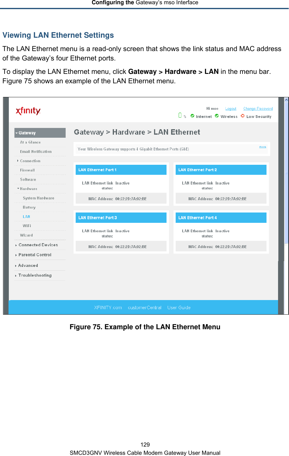
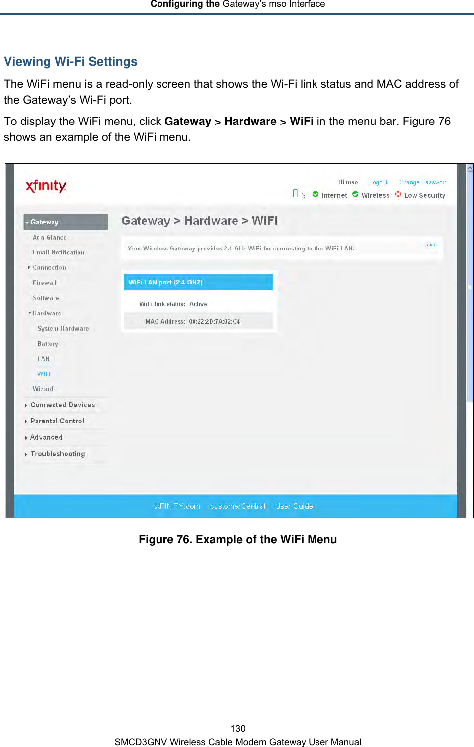
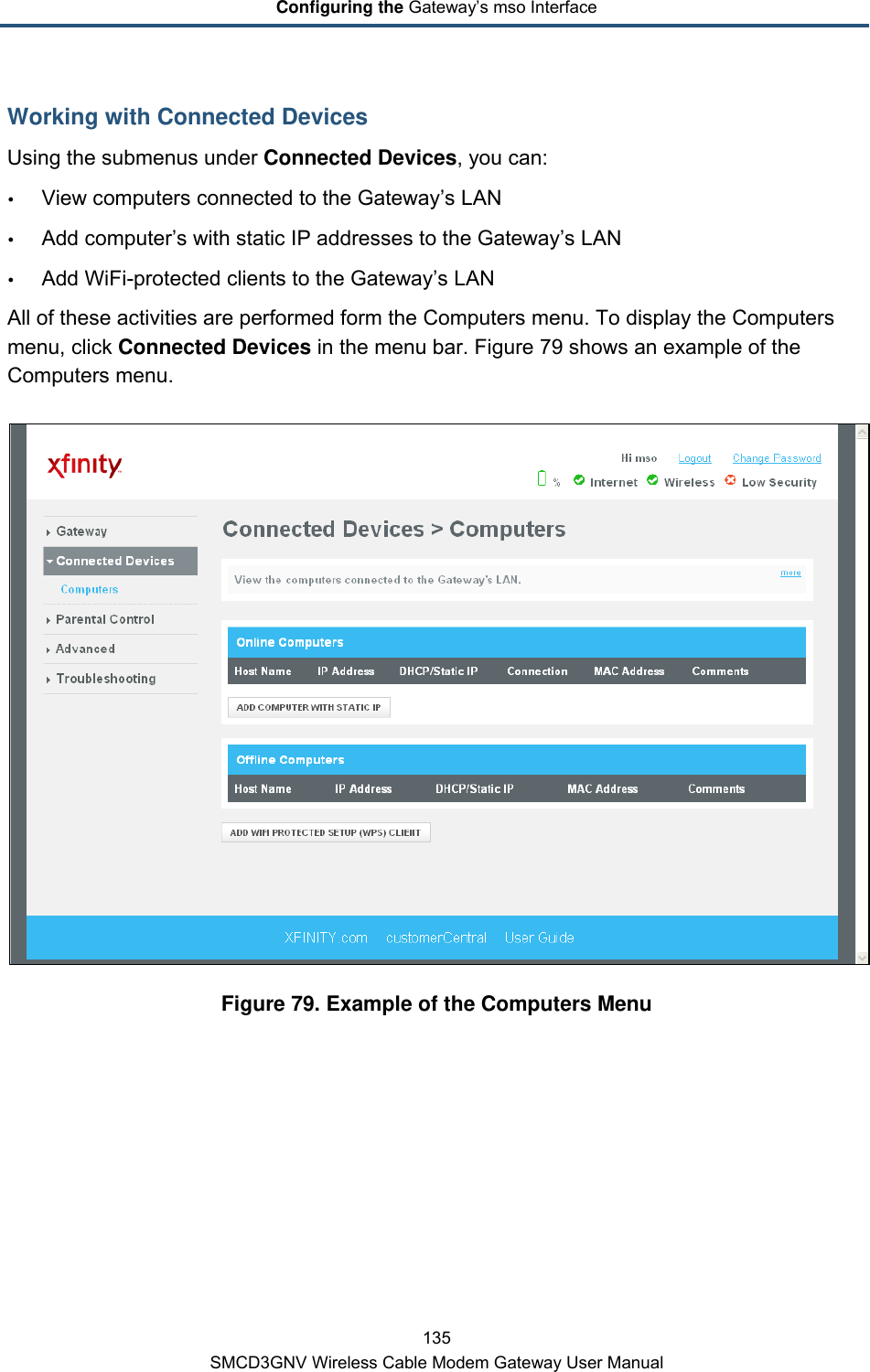
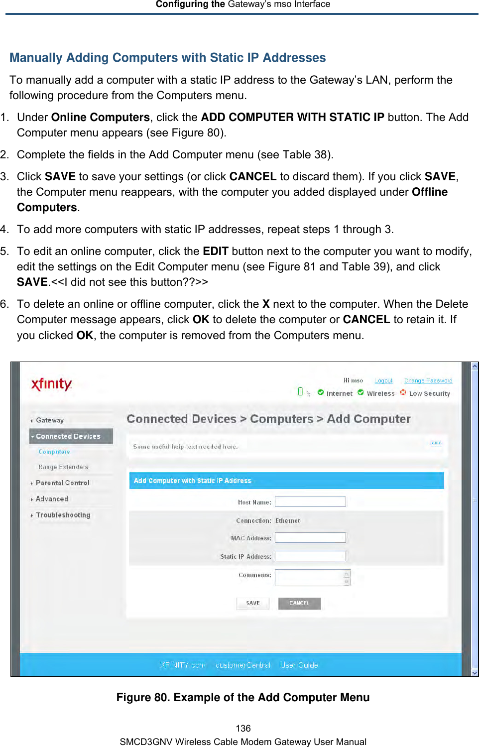
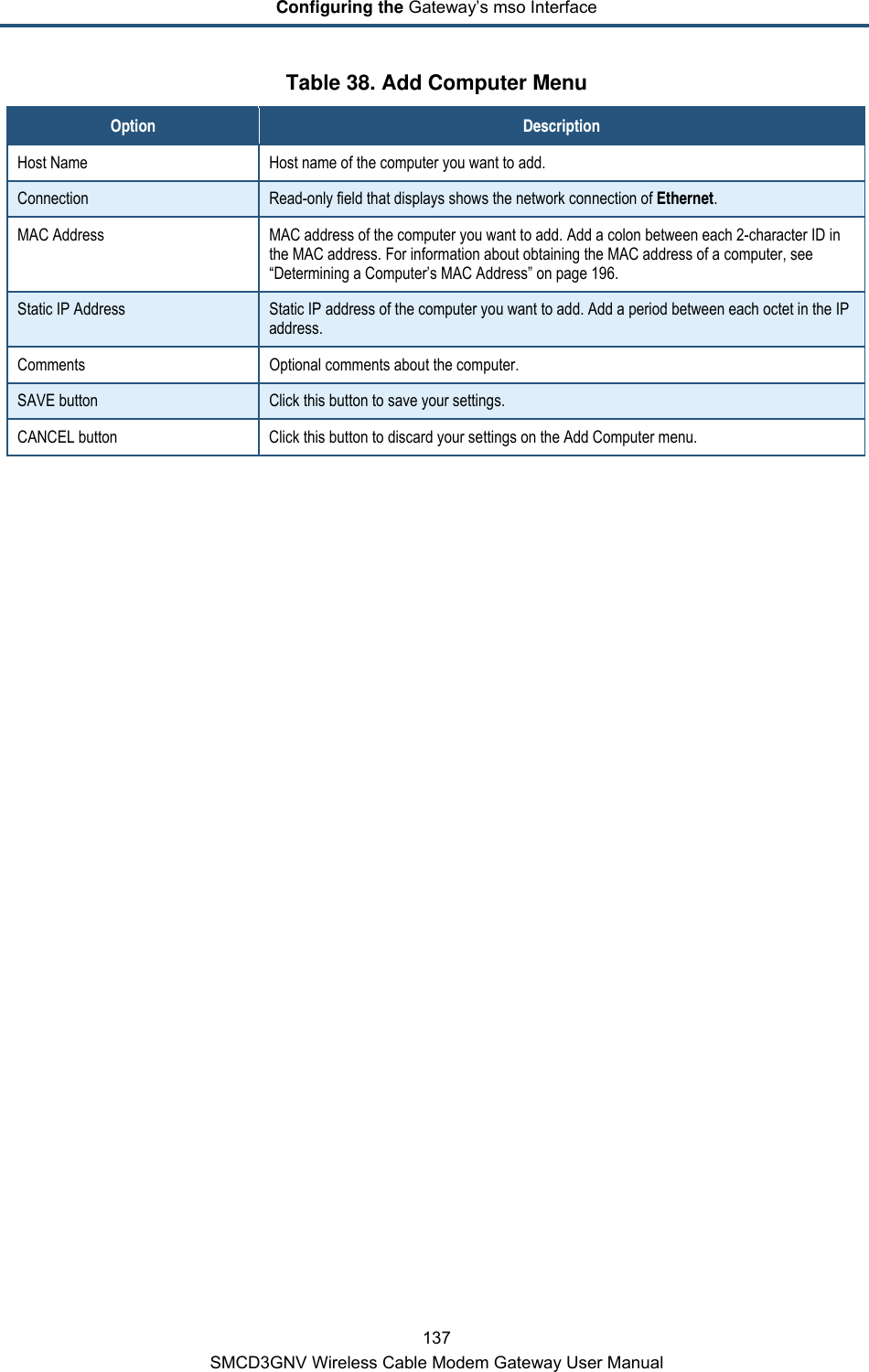
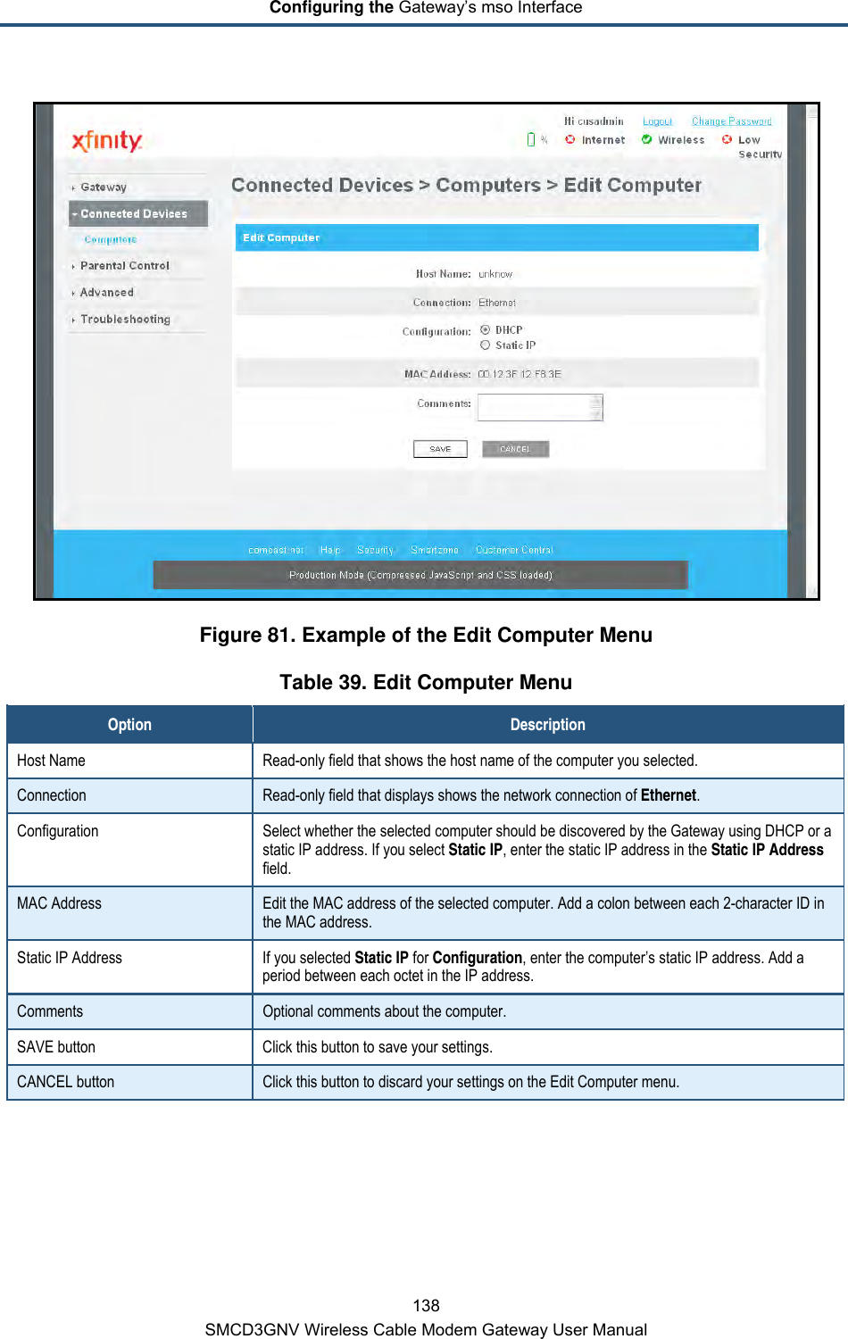
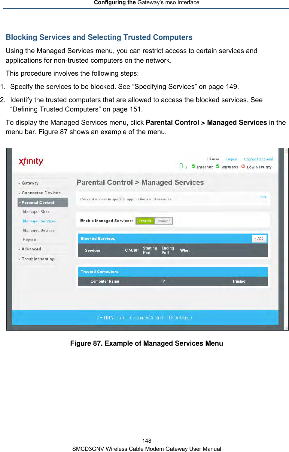
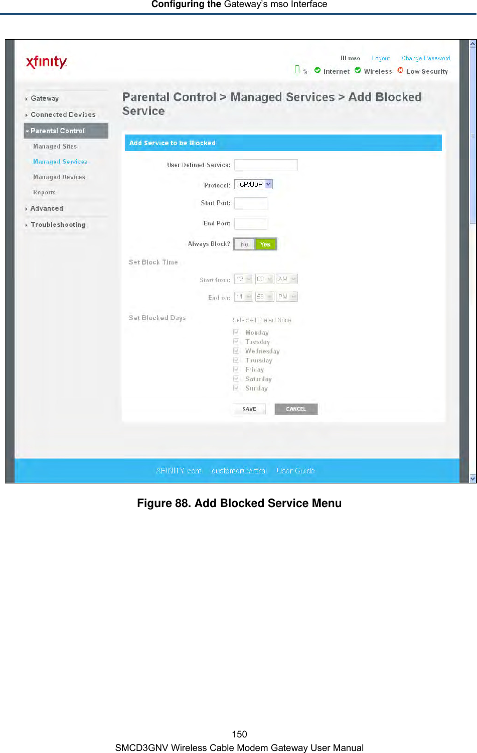
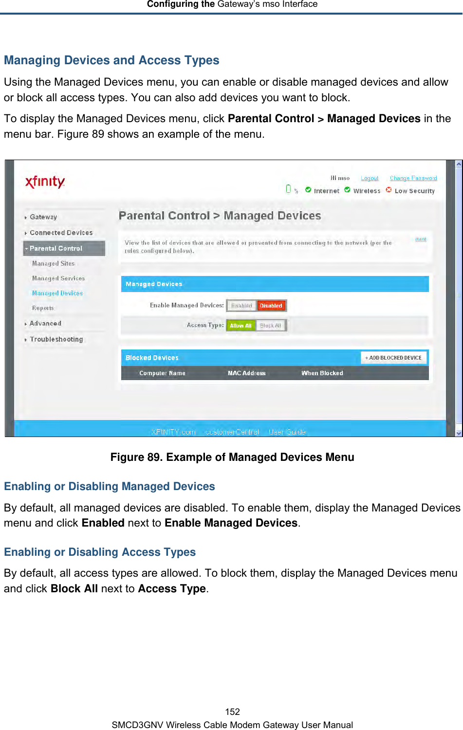
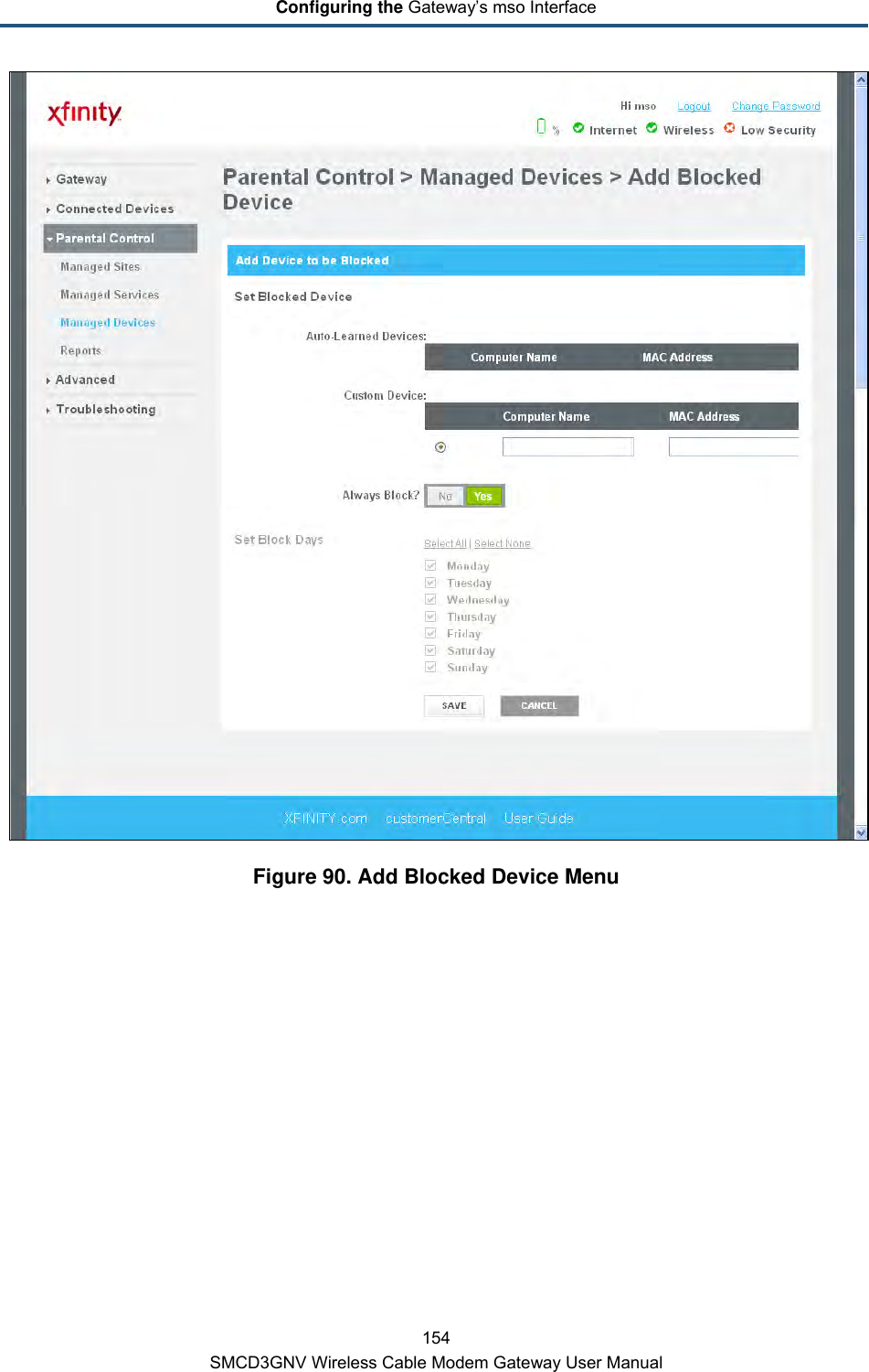
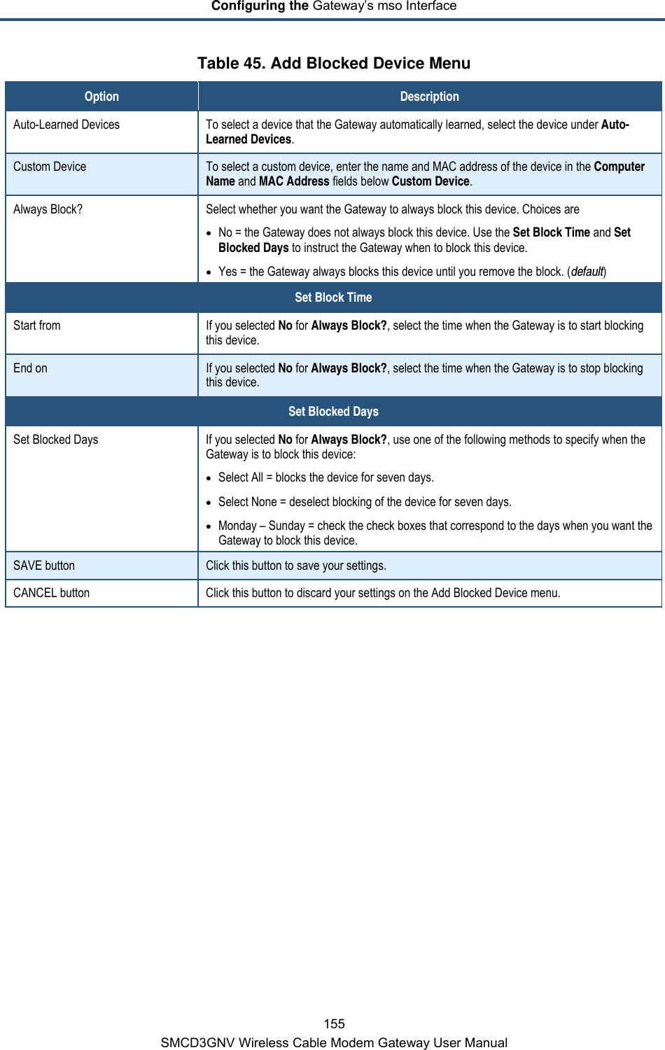
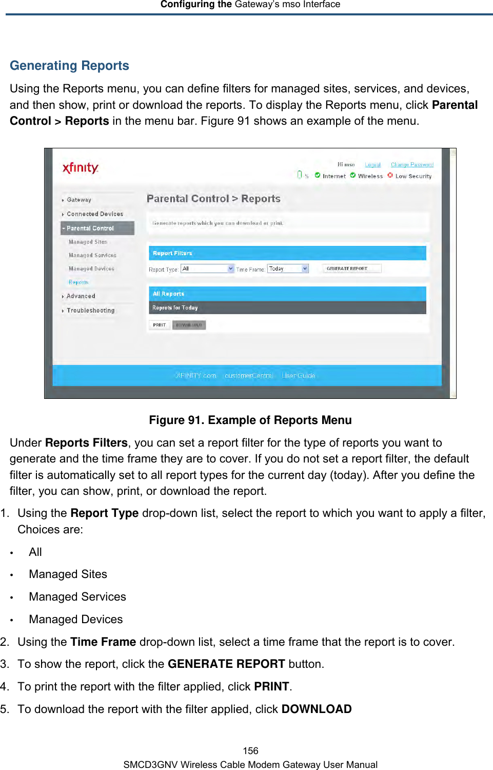
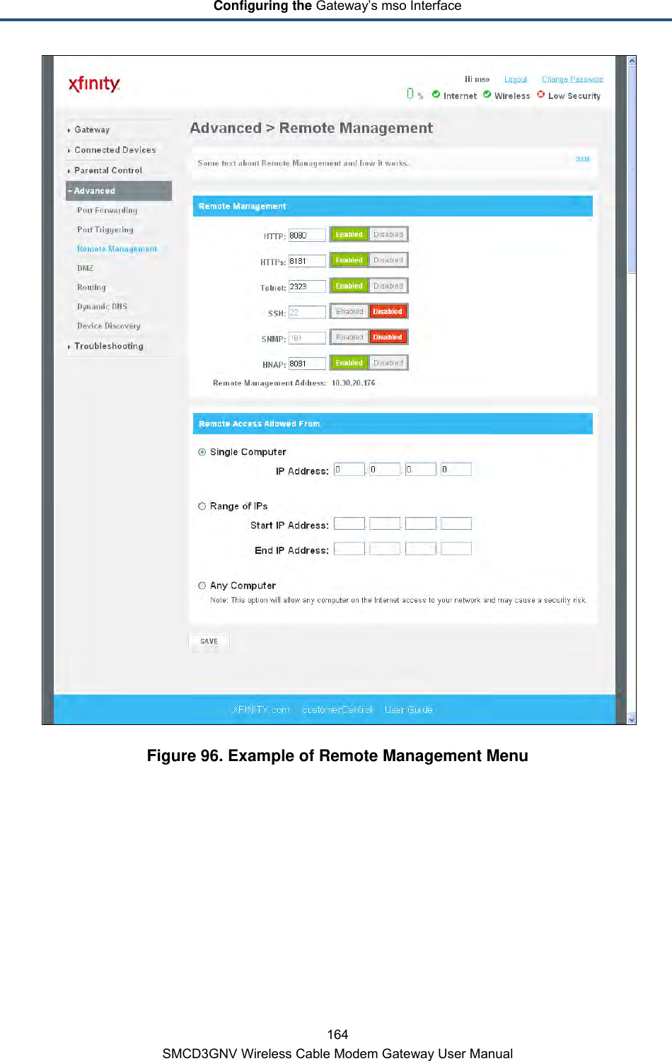
![Preface x SMCD3GNV Wireless Cable Modem Gateway User Manual Typographic Conventions This document also uses the following typographic conventions. Convention Description Bold Indicates text on a window, other than the window title, including menus, menu options, buttons, fields, and labels. Italic Indicates a variable, which is a placeholder for actual text provided by the user or system. Angled brackets (< >) are also used to indicate variables. screen/code Indicates text that is displayed on screen or entered by the user. < > angled brackets Indicates a variable, which is a placeholder for actual text provided by the user or system. Italic font is also used to indicate variables. [ ] square brackets Indicates optional values. { } braces Indicates required or expected values. | vertical bar Indicates that you have a choice between two or more options or arguments.](https://usermanual.wiki/SMC-Networks/DORY3A/User-Guide-1725475-Page-10.png)