SMC Networks RB6741 Zigbee Touchscreen Security System User Manual
SMC Networks Inc Zigbee Touchscreen Security System
user manual

Quick Start Guide
RB6741-Z Touchscreen Security System

SMC Networks
20 Mason
Irvine, CA. 92618
U.S.A.
Copyright © 2013 SMC Networks
All Rights Reserved
Information furnished by SMC Networks, Inc. (SMC) is believed to be accurate and reliable. However,
no responsibility is assumed by SMC for its use, or for any infringements of patents or other rights of
third parties which may result from its use. No license is granted by implication or otherwise under
any patent or patent rights of SMC. SMC reserves the right to change specifications at any time
without notice
No part of this publication may be reproduced or transmitted in any form or by any means, electronic
or mechanical, including photocopying and recording, or stored in a database or retrieval system for
any purpose without the express written permission of SMC.
Microsoft and Windows are registered trademarks of Microsoft Corporation. Apple and Macintosh are
registered trademarks of Apple, Inc. All other brands, product names, trademarks, or service marks
are property of their respective owners.
This product (Model: RB6741-Z) includes software code developed by third parties, including software
code subject to the GNU General Public License (“GPL”) or GNU Lesser General Public License
(LGPL”). As applicable, the terms of the GPL and LGPL, and information on obtaining access to the
GPL code and LGPL used in this product, are available to you at http://gpl.smc.com/. The GPL code
and LGPL code used in this product is distributed WITHOUT ANY WARRANTY and is subject to the
copyrights of one or more authors. For details, see the GPL Code and LGPL Code for this product
and the terms of the GPL and LGPL.
RB6741-Z Touchscreen Security System Quick Start Guide
January 7, 2013

iii
SMCRB6741-Z Touchscreen Security System Quick Start Guide
Contents
1 Using the Touchscreen ........................................................................................ 1
Understanding the Screen ......................................................................................... 2
Security Status Header ........................................................................................ 3
System & Zone Trouble Header ........................................................................... 4
Content Area ........................................................................................................ 5
Understanding Arming Modes ................................................................................... 6
Arm Away Mode................................................................................................... 6
Arm Stay Mode .................................................................................................... 7
Arm Night Mode ................................................................................................... 7
Arming and Disarming the System ................................................................. 7
Arming the System from the Touchscreen ................................................................. 8
Cancelling the Arming Process ............................................................................ 9
Disarming the System ................................................................................................ 9
Sending an Emergency Alarm ................................................................................. 11
2 Evacuation and Emergency Plans .................................................................... 12
Evacuation Plan ....................................................................................................... 12
Additional Emergency Preparations ......................................................................... 12
3 Quick-Reference Tables ..................................................................................... 13
System & Security Settings, Ranges, and Defaults .................................................. 13
Screen Settings, Ranges, and Defaults ................................................................... 15
Advanced Settings Range and Defaults ................................................................... 15
Appendix A - Compliances ................................................................................... 16
1
SMCRB6741-Z Touchscreen Security System Quick Start Guide
1 Using the Touchscreen
Congratulations on your purchase of the RB6741-Z Touchscreen.
The RB6741-Z Touchscreen is the center of your home security system. This Android-
powered device allows you to perform actions such as arming and disarming your security
system, monitoring the status of your security sensors, and sending emergency alarms.
This Quick Start Guide provides an overview of the Touchscreen and its basic operation.
This guide assumes the Touchscreen has been activated and you have been assigned a
security code. For more information, refer to the RB6741-Z Touchscreen Security System
Installation Manual and the RB6741-Z Touchscreen Security System User Manual. For
detailed information about operating an Android device, refer to the Android documentation
provided by Google.
WARNING: The rechargeable battery that comes with your Touchscreen is only
available through your service operator. If your battery needs to be replaced,
contact your service operator to arrange for replacement.
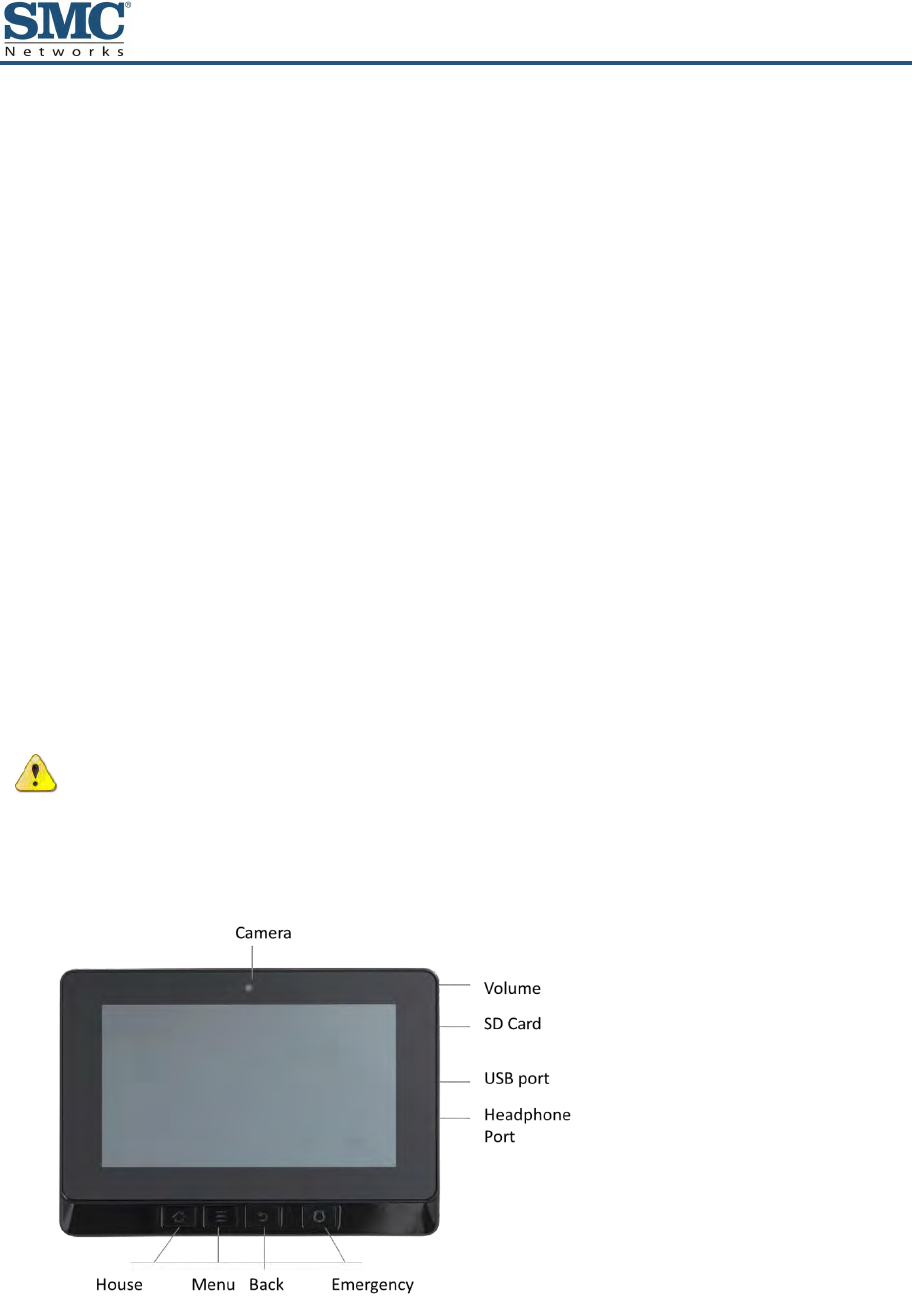
Figure 1-1 shows the major components of the Touchscreen and Table 1-1 describes them.
Figure 1-1. Major Touchscreen Components
2
SMCRB6741-Z Touchscreen Security System Quick Start Guide
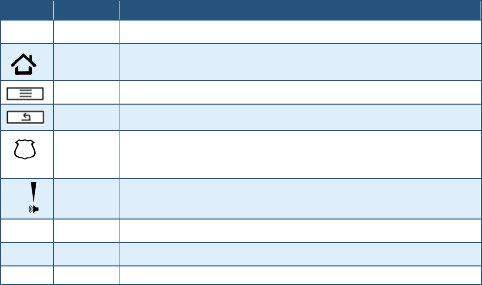
Table 1-1. Major Touchscreen Components
Icon
Name
Description
Camera
Camera Lens
Home
Go to the Home (main) screen in the Touchscreen screen.
Menu
Display the configuration menu.
Back
Return to the previous screen.
Emergency
Display icons for fire, medical, or police service. Tap one of these icons to immediately send an alarm to the
appropriate call center. The button is located at the bottom right in front of the device. When A/C power is
available, this button is lit. For more information, refer to the RB6741-Z Touchscreen Security System User
Manual.
Volume Switch
Adjust the volume of the Touchscreen. (Button is located on the right side.)
SD Card
Port for attaching an SD card.
USB Port
Port for attaching a Universal Serial Bus device.
Headphone Jack
Port for attaching headphones.
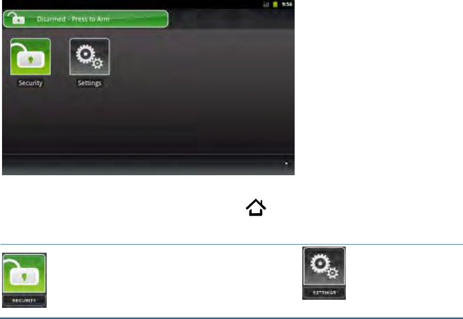
Understanding the Screen
The Touchscreen communicates with your security system. It combines security and home
controls on an intuitive graphical interface to provide:
A real-time view of the system statuses
Tools to manage your security system
Additional optional applications such as news and weather
The first screen displayed is the Home screen. From this screen, you tap buttons to navigate
through menus to access the functions you desire. If the screen is black (showing nothing), it
means the system is not receiving A/C power or the display is powered off to conserve
battery life.
The screen is organized into the following operational sections:
Security Status Header – see “Security Status Header” on page 3
System & Zone Trouble Header – see “System & Zone Trouble Header” on page 4
Content Area – see “Content Area” on page 5
3
SMCRB6741-Z Touchscreen Security System Quick Start Guide
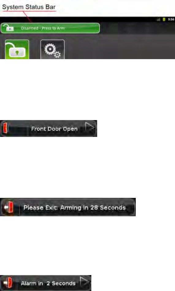
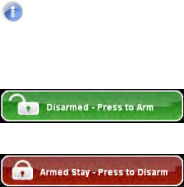
Security Status Header
The Security Status header appears in the top-left area of the Touchscreen. It tells you
whether the system is armed or disarmed and other information. Tap this header to arm or
disarm the system.
Problems that Prevent Arming
If you encounter problems that would prevent arming, such as a monitored door or window
being opened, an announcement replaces the Arm/Disarm status.
Exit Delay
During the Exit Delay, the header announces the number of seconds until the system is
armed.
Entry Delay
During the Entry Delay, the header announces the number of seconds before the alarm
sounds.
4
SMCRB6741-Z Touchscreen Security System Quick Start Guide
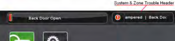
System & Zone Trouble Header
The System & Zone Trouble header appears in the top-right area of the Touchscreen. It
displays when:
There is a connectivity (cellular, broadband, and so on)
Power problems with the Touchscreen
When a sensor goes down, such as due to a battery failure
When a sensor is being tampered with, such as the cover being opened
System Reports Trouble
If the system reports trouble, it sounds an audible alert regularly to make you aware of the
problem.
If a System & Zone header appears, tap it to show the Troubles list, which lists all current
troubles with the Touchscreen and sensors.
5
SMCRB6741-Z Touchscreen Security System Quick Start Guide
Content Area
The Content area is the interactive functionality of your Touchscreen where the Touchscreen
apps appear. When you use or modify an app, the menus and tools appear here.
The Home screen is the default interface when you access the Touchscreen. Return to this
screen at any time by pressing the Home button on the bottom-left of the device.
The Touchscreen always provides the following apps:
Select the Security app to view options related to
arming/disarming the system, enabling/disabling
security zones, viewing history logs, and recent
security zone events.
Select the Settings app to
access tools to modify the
Touchscreen configurations.

6
SMCRB6741-Z Touchscreen Security System Quick Start Guide
Understanding Arming Modes
You can arm the system for multiple scenarios:
Arm Away — everybody is leaving. See “Arm Away Mode” below.
Arm Stay — people are active inside. See “Arm Stay Mode” on page 7.
Arm Night — everybody is going to bed. See “Arm Night Mode” on page 7.
Different arming modes use different rules for when sensors are tripped and for Entry/Exit
delays.
An Exit delay is a short period of time after the system is armed for you to leave the
premises (default 60 seconds).
An Entry delay gives you time to disarm the system when you reenter the premises
(default 30 seconds). You must enter a valid keypad code within the Entry delay period
to avoid sounding an alarm.
Consult with your installer or Customer Care representative to customize the Entry and Exit
delays on your system.
Note: After the alarm is faulted, the Alarm Transmission Delay period starts (see page 10).
If the central system loses all connectivity with your Touchscreen in the Armed state and
during the Entry Delay period, an alarm is sent to the central monitoring station immediately.
This response prevents an intruder from trying to stop an alarm by destroying the
Touchscreen.
Arm Away Mode
Arm Away mode is used when everyone is leaving the house. The following rules apply:
Alarm trips immediately if a monitored Perimeter zone (non-entry/exit door or window) is
opened.
Interior motion detectors are armed.
Entry/Exit zones start an Entry Delay.
Exit Delay starts when the system is armed.
7
SMCRB6741-Z Touchscreen Security System Quick Start Guide
Arm Stay Mode
Arm Stay mode is used to arm the system when there are people in the premises. The
following rules apply:
Alarm trips immediately if a monitored Perimeter zone (non-entry/exit door or window) is
opened.
Interior motion detectors are not armed.
Entry/Exit zones start an Entry Delay.
Exit Delay starts when the system is armed.
Exit Delay does not beep and is twice the length of Alarm Away mode.
Arm Night Mode
Arm Night mode is used when everyone is going to bed.
This mode works the same as Arm Stay mode, except there is no Entry Delay period. If an
entry/exit zone is opened, an alarm sounds immediately.
Note: There is an Exit Delay period that works the same as in Arm Stay mode.
Arming and Disarming the System
The Security status of your security system appears in the Security Status header.
Message that the Security Status header displays
when the status is “Disarmed”. Tap to arm the
system.
Message that the Security Status header displays
when the status is “Armed”. Tap to disarm the
system.
8
SMCRB6741-Z Touchscreen Security System Quick Start Guide
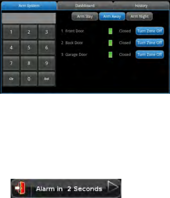
Arming the System from the Touchscreen
To arm the system from the Touchscreen:
1. Tap the Security Status header when it is in Disarmed state. The Security Options screen
appears, with a keypad and the Arm System tab open.
2. Tap an arming mode (Arm Stay, Arm Away, or Arm Night) and enter your security code.
The Security Status header changes to display a countdown message.
The text of the message varies, according to which arming mode you selected.
Observe the following guidelines:
– If you select Arm Away mode, you have until the Exit Delay is over to exit the
premises.
– Otherwise, the system is automatically armed in Arm Stay mode. There is still an Exit
Delay period for the other Arming modes as well, but they do not require that the
door open and close during the period.
– If you open and shut an Entry/Exit door during the Exit Delay and then re-enter the
premise, the Exit delay restarts at 120 seconds for Arm Stay and Arm Night or 60
seconds for Arm Away. It only does this one time. If the wrong code is entered, the
countdown timer resets to 60 or 120 seconds.
– If an Entry/Exit door is left open at the end of Exit Delay, the Entry Delay immediately
starts and, if the system is not disarmed, an alarm sounds.
9
SMCRB6741-Z Touchscreen Security System Quick Start Guide
Cancelling the Arming Process
If you arm the system in Arm Away or Arm Stay mode, the Security Status header displays a
countdown of the number of seconds until the Exit Delay expires. You can choose to cancel
the arming process.
To cancel the arming process:
1. Tap the Security Status header while it displays a countdown. The Security app appears
with a keypad and the Disarm System tab is active. The view from the camera(s), if any, is
displayed.
2. Enter your security code to stop the arming process.
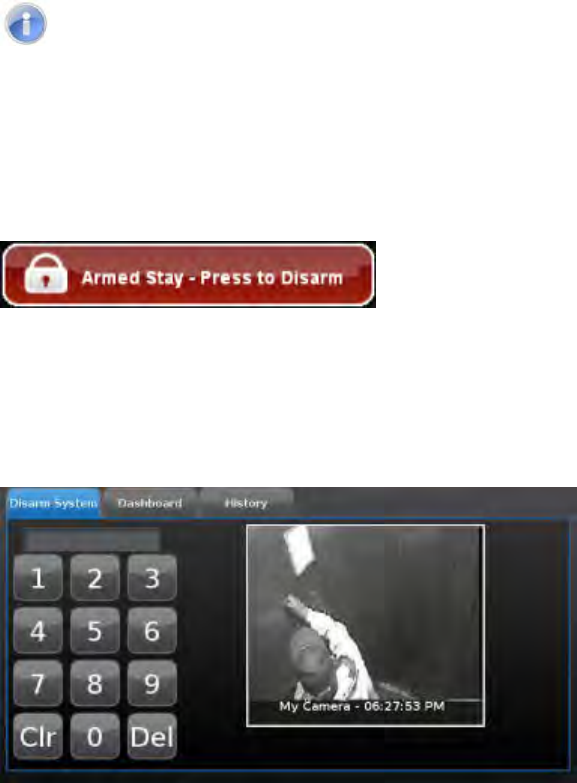
Disarming the System
When entering armed premises, an Entry Delay period starts:
During the Entry Delay, the header changes to announce the number of seconds before
the alarm goes off.
The Security app displays a keypad.
The Touchscreen beeps once every second, until the last 10 seconds when it beeps
twice a second.
If a valid keypad code is not entered by the end of the Entry Delay period, an alarm sounds.
For most reasons, from the time an alarm sounds or starts silently, you have 30 seconds
(default) to enter a valid keypad code to disarm the system and prevent an alarm from being
sent to the central monitoring station. This is called the Alarm Transmission delay or the
Abort Window.
10
SMCRB6741-Z Touchscreen Security System Quick Start Guide
The Alarm Transmission Delay is a required period that prevents a report to the central
station if an alarm was triggered innocently.
Note: Emergency alarms (see “Sending an Emergency Alarm” on page 11) and smoke alarms
are reported without an Alarm Transmission delay or an Entry Delay. Consult Customer Care
to ascertain the number of seconds configured for the Alarm Transmission Delay on your
system.
To disarm the system from the Touchscreen:
1. Tap the Security Status header when it is in Armed state.
The Security app appears with a keypad and the Disarm System tab active. If the sensor
that was tripped is associated with a camera, the view from that camera is displayed. If
the sensor is not associated with a camera, the view from the default camera is
displayed.
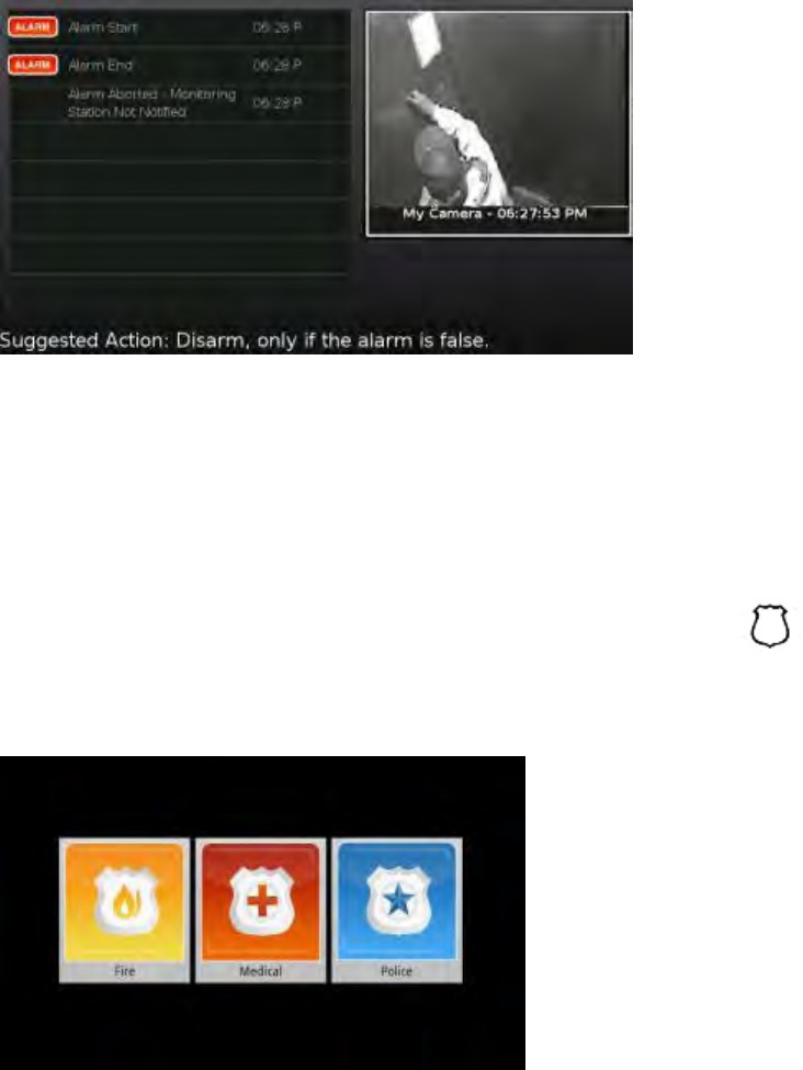
2. Enter your security code. If the alarm was triggered, the camera view and alarm history are
displayed.
11
SMCRB6741-Z Touchscreen Security System Quick Start Guide
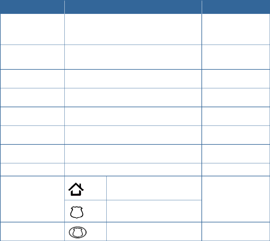
Sending an Emergency Alarm
You can manually trip an alarm in the event of an emergency by clicking the Emergency
button. Emergency alarms are reported without an Entry delay or Alarm Transmission delay.
To manually trip an alarm:
1. Press the Panic button on the lower front area of the Touchscreen.
The Emergency screen appears.
2. Perform one of the following steps:
– Tap Fire to send an alarm for emergency fire assistance. The Touchscreen sounds a
repeating, high-pitched chime.
– Tap Medical to send an alarm for emergency medical assistance. The Touchscreen
sounds an audible, repeating, triple beep signal.
– Tap Police to send an alarm for police assistance. The Touchscreen displays a
Police Panic In Progress alert on the Touchscreen but, by default, will not issue an
audible signal. Tap the alert to sound an audible, continuous, high-pitched chime.

12
SMCRB6741-Z Touchscreen Security System Quick Start Guide
2 Evacuation and Emergency Plans
Evacuation Plan
Develop an emergency evacuation plan for use in the event of fire. Here are some
recommendations from the National Fire Protection Association.
Make an evacuation plan for how to leave your home in the case of fire or other
emergency. Sketch a map of your home that shows all the doors and windows. Discuss
the plan with everyone in your home so that everyone will know what to do.
Have at least two ways to exit each room. Make sure that windows and doors open
easily.
Discuss with your family and agree on a single meeting location outside your home.
In the event of fire, get out and stay out. Don’t go back inside for people, pets or
possessions.
Do not open a door if the handle is hot.
If there is smoke stay low to the ground and go under the smoke.
Escape your home before calling the fire department. Call the fire department and police
from the outside meeting place using your cell phone or call from a neighbor’s phone.
Practice your home evacuation plan.
Additional Emergency Preparations
Do not wait until an emergency occurs to make a plan. Talk to each other about what
each person should do in different types of emergency.
Learn your security system. Get to know how to arm and disarm it and what to do when
the authorities or central monitoring calls.
Make sure everyone (who should know) knows the Secret Word, when to use it, and that
it should not be shared.
Understand the difference between your keypad code and the duress code.
Understand that you should never enter the premises if you hear an alarm. Call police
from a cell phone or a neighbor’s phone.
13
SMCRB6741-Z Touchscreen Security System Quick Start Guide
3 Quick-Reference Tables
This chapter provides tables that list the ranges and default settings for features in your
security system. The tables are grouped in the following categories:
System & Security settings (see page 13)
Touchscreen device settings (see page 15)
Advanced system settings (see page 15)
System & Security Settings, Ranges, and Defaults
Feature
Comments
Ranges & Defaults
Exit Delay
The time allotted for the customer to exit the premises when the
security system is armed.
The Exit Delay for Arm Stay and Arm Night modes is twice the
configured Exit Delay up to 120 seconds.
Default: 60 seconds
Range: 45 seconds to 240
seconds
Exit Delay Progress
Annunciation
Touchscreen beeps once per second. Twice per second during the
last 10 seconds.
Disabled for Arm Stay & Arm
Away.
This feature is not configurable.
Exit Delay Restart
Entry/Exit zone is faulted, restored and then faulted again prior to the
end of the exit delay, then Exit Delay restarts.
One time only.
This feature is not configurable.
Exit Error
If an Entry/Exit door is left open at the end of Exit Delay, the Entry
Delay starts and, if the system is not disarmed, an alarm sounds.
This feature is not configurable.
Unvacated Premises
During Arm Away, if no Entry/Exit Zone opens and closes during the
Exit Delay, the Arming Mode reverts to Armed Stay.
This feature is not configurable.
Entry Delay
The time allotted for the customer to disarm the system after tripping
an Entry/Exit security zone.
Default: 30 seconds
Range: 30 to 240 seconds
Entry Delay Progress
Annunciation
Touchscreen beeps once per second Twice per second during the
last 10 seconds.
This feature is not configurable.
Disarm
Enter a keypad code to disarm the system.
This feature is not configurable.
Control Buttons
Home button
The functions of these buttons
cannot be changed.
Emergency Alarm button
Emergency Alarms
(aka manual alarms)
Touchscreen:
Press to access Emergency Alarm options
The functions of these buttons
cannot be changed.

14
SMCRB6741-Z Touchscreen Security System Quick Start Guide
Feature
Comments
Ranges & Defaults
Alarm Transmission Delay
(aka Abort Window or
Communicator Delay)
Length of time after an alarm sounds for the customer to enter a valid
keypad code to prevent alarm from being sent to central station.
Your system is configured with a communicator delay. A
communicator delay will prevent a report to the central station if the
control panel is disarmed within 15-45 seconds after an intrusion
alarm is triggered. Note that fire-type alarms are normally reported
without a delay.
Default: 30 sec.
Range: Minimum is 15 sec. and
the maximum is 45 sec.
Disarming During the Alarm
Transmission Delay
System disarmed by entering a valid keypad code in the
Touchscreen or a key pad. If invalid keypad code entered, alarm
restarts.
This feature is not configurable.
When alarms are successfully
aborted (that is, disarmed
during the Alarm Transmission
Delay period)
If system is disarmed within the Alarm Transmission Delay period, no
alarm transmission occurs. Contacts can opt not to receive SMS
and/or email messages notifying them when an alarm was aborted
and that central monitoring was not notified.
By default, verify contacts are
notified by SMS and email when
an alarm is disarmed during the
Alarm Transmission Delay
period.
Cancel Window
For 5 minutes after the end of the Abort Window, customer can
disarm system to send an Alarm Cancel to central monitoring.
This feature is not configurable.
Duress Code
A four digit code that sends silent alarm immediately when used to
arm or disarm the system. Otherwise, works the same as the Master
keypad code.
Default: Duress Code is disabled.
Initiating Emergency Alarms
(aka manual alarms)
This is a two-step action from the Touchscreen.
Not configurable.
Cross Zoning
Two security zones that only trip an alarm if they are both faulted
within a configured period of time. Can only be created after the
security zones have been added in a separate step.
Default: 10 seconds
Range 1 second to 999 seconds.
Swinger Shutdown
After the Touchscreen has sent an alarm the set number of times
(trips) to central monitoring, no more alarms will be sent to central
monitoring for 48 hours or until the security system is disarmed.
Default: 2 trips
Range: 1 to 6 trips
Fire Alarm Verification
When enabled, central only contacts the authorities when multiple
smoke detectors are faulted OR a detector is in an alarm for 60
seconds or more.
Default: Disabled
Call Waiting
Old-fashioned security systems use phone lines to send alarms to central monitoring, so they require a
caution included with their control panels alerting the installer that call waiting features can prevent
successful connection to the central station.
Since the Touchscreen connects to central monitoring over broadband and cellular, this alert is not
required.
System Test
Perform the system test described in the RB6741-Z Touchscreen Security System User Manual
Communications
Test the security system to ensure that it is in proper communication with central monitoring, as
described in the RB6741-Z Touchscreen Security System User Manual.
Test In Progress
The titles of all alarm test process screens begin with “Alarm Test”.
Not configurable.
Automatic Termination of Test
There are no conditions that would result in the automatic termination of Test mode. The user must tap
the Disarm button on the Alarm Test screen to end the alarm test.
Screen Brightness
The relative brightness of the Touchscreen screen.
Default: 10 (brightest)
Range: 1 to 10
15
SMCRB6741-Z Touchscreen Security System Quick Start Guide
Screen Settings, Ranges, and Defaults
Feature
Comments
Ranges & Defaults
Automatic Screen Dimming
Idle Timeout
Default: 30 minutes
Range: 5 minutes to 30 minutes
(in 5 minute increments)
Dimming Level
Default: 10 (brightest)
Range: 1 to 10
Screen Nighttime Settings
Backlight off at night
Default: No
Range: Yes or No
Backlight off time
Default: 12:00 .A.M.
Backlight on time
Default: 12:00 .A.M.
Screensaver Configuration
Minutes Inactive before screensaver
becomes active.
Default: 30 minutes
Range: 5 minutes to 30 minutes
(in 5 minute increments)
Sound Configuration
Volume control
Default: 13 (loudest)
Range: 0 (mute) to 13
Advanced Settings Range and Defaults
Feature
Comments
Default
Expose Personal Router to
Internet
Whether the retail router connected to the
security system router is exposed to the Internet.
Default: Not exposed

16
SMCRB6741-Z Touchscreen Security System Quick Start Guide
Appendix A - Compliances
FCC Notice
FCC ID: JI5-RB6741
Federal Communication Commission Interference Statement
This equipment has been tested and found to comply with the limits for a Class B digital
device, pursuant to Part 15 of the FCC Rules. These limits are designed to provide
reasonable protection against harmful interference in a residential installation. This
equipment generates, uses and can radiate radio frequency energy and, if not installed and
used in accordance with the instructions, may cause harmful interference to radio
communications. However, there is no guarantee that interference will not occur in a
particular installation. If this equipment does cause harmful interference to radio or television
reception, which can be determined by turning the equipment off and on, the user is
encouraged to try to correct the interference by one of the following measures:
Reorient or relocate the receiving antenna.
Increase the separation between the equipment and receiver.
Connect the equipment into an outlet on a circuit different from that to which the
receiver is connected.
Consult the dealer or an experienced radio/TV technician for help.
FCC Caution
Changes or modifications not expressly approved by the party responsible for compliance
could void the user's authority to operate the equipment.
This device complies with FCC Rules Part 15. Operation is subject to the following two
conditions: (1) This device may not cause harmful interference, and (2) this device must
accept any interference, including interference that may cause undesired operation of the
device
This device and its antenna(s) must not be co-located or operation in conjunction with any
other antenna or transmitter.
IMPORTANT NOTE:
FCC Radiation Exposure Statement:
This equipment complies with FCC radiation exposure limits set forth for an uncontrolled
environment. This equipment should be installed and operated with minimum distance 20cm
between the radiator & your body.
17
SMCRB6741-Z Touchscreen Security System Quick Start Guide
IC Notice / Avis IC
IC: 4137A-RB6741
Industry Canada Statement
This Class B digital apparatus complies with Canadian ICES-003
This device complies with Industry Canada license-exempt RSS standard(s). Operation is
subject to the following two conditions: (1) this device may not cause interference, and (2)
this device must accept any interference, including interference that may cause undesired
operation of the device.
This device and its antenna(s) must not be co-located or operation in conjunction with any
other antenna or transmitter.
The term "IC" before the equipment certification number only signifies that the Industry
Canada technical specifications were met.
Déclaration d'Industrie Canada
Cet appareil numérique de la classe B est conforme à la norme NMB-003 du Canada.
Le présent appareil est conforme aux CNR d'Industrie Canada applicables aux appareils
radio exempts de licence. L'exploitation est autorisée aux deux conditions suivantes : (1)
l'appareil ne doit pas produire de brouillage, et (2) l'utilisateur de l'appareil doit accepter tout
brouillage radioélectrique subi, même si le brouillage est susceptible d'en compromettre le
fonctionnement.
Cet appareil et son antenne (s) ne doit pas être co-localisés ou fonctionnement en
association avec une autre antenne ou transmetteur.
Le terme « IC » avant le numéro d'homologation ne signifie seulement que les normes
d'Industrie Canada ont été respectées.
IMPORTANT NOTE:
IC Radiation Exposure Statement:
This devise is only authorized for use in a mobile or fixed application. At least 20cm (8
inches) of separation distance between the touchscreen and the user’s body must be
maintained at all times to ensure compliance with the Industry Canada RF Exposure
Requirements.
Informations d'Exposition aux RF
Cet appareil est uniquement pour une utilisation dans une application mobile ou fixe. Au
moins 20 centimètres de distance de séparation entre l’écran tactile et le corps de
l’utilisateur doit être maintenue en tout temps pour assurer la conformité avec les exigences
de la Industrie Canada, l’ exposition.
18
SMCRB6741-Z Touchscreen Security System Quick Start Guide
Device Purpose
Fire/Alarm Central Panel
UL and ULC Notices
This device complies with UL 985, UL1023, UL1635, ULC S545, ULC C1023.
Limitations of Security Products
Security products and alarm systems do not offer guaranteed protection against burglary,
fire, or other emergencies. They may fail to warn for diverse reasons, including (but not
limited to): power failure, dead batteries, improper installation, coverage, coverage areas
overlooked during installation, defeat by technically sophisticated intruders, component
failure, or inadequate maintenance. Alarm systems should be checked weekly to ensure that
all devices are working properly.
AN ALARM SYSTEM IS NOT A SUBSTITUTE FOR INSURANCE.
Conditions Resulting In False Alarms
Any installation of the RB6741-Z not in accordance to this manual may result in the
occurrence of false alarms.
Conditions Resulting In Impaired Operation
Any installation of the RB6741-Z not in accordance to the National Electric Code (NFPA70)
may result in improper operation as described in this manual.
Protective Features
The stand, RB6741-BT, included with the RB6741-Z Touchscreen protects against
unwanted tampering of the device. Only operate the RB6741-Z Touchscreen with the
protective stand attached.
US Version Only: Use the RB6741-Z power adapter with restraining bracket to secure the
plug in adapter to the receptacle. Only use the RB6741-Z with the power adapter and
restraining bracket properly installed. For installation instructions, refer to the RB6741-Z
Touchscreen Security System Installation Manual.