SMC Networks SMC2585W-G EliteConnect 2.4GHz Dual-Radio 802.11g Bridge User Manual SMC2585W GManual v2
SMC Networks Inc EliteConnect 2.4GHz Dual-Radio 802.11g Bridge SMC2585W GManual v2
UserManual.wiki
>
SMC Networks
>
SMC2585W G User Manual
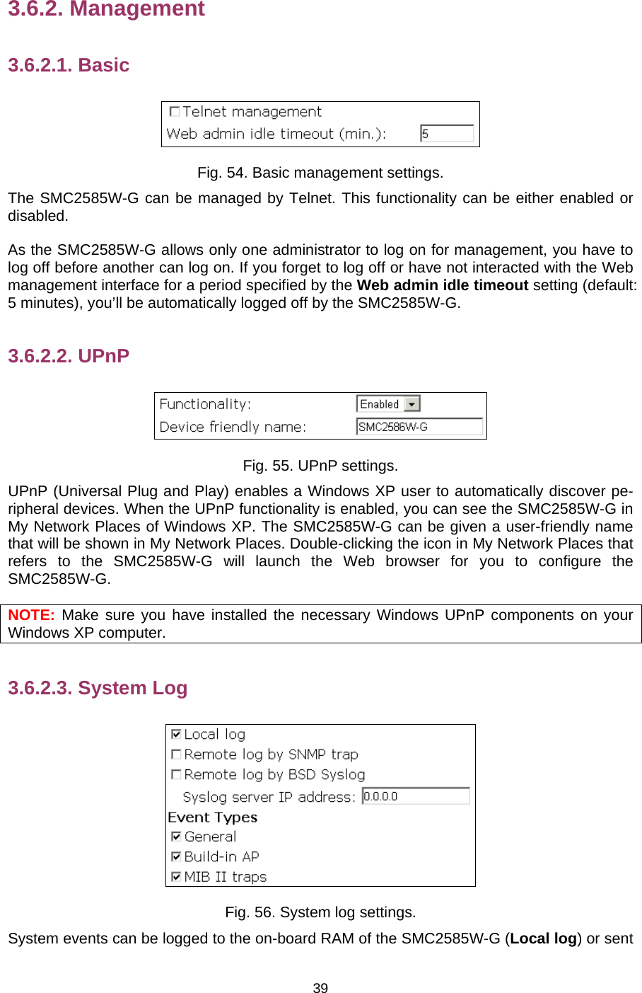
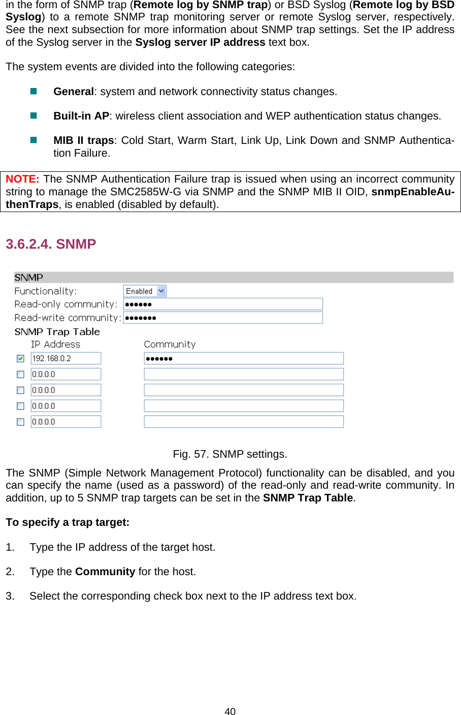
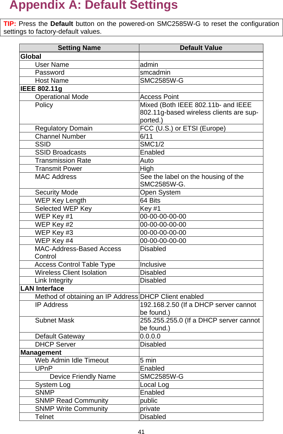
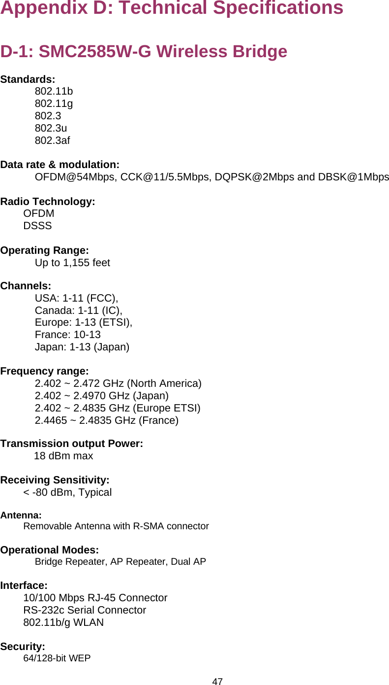
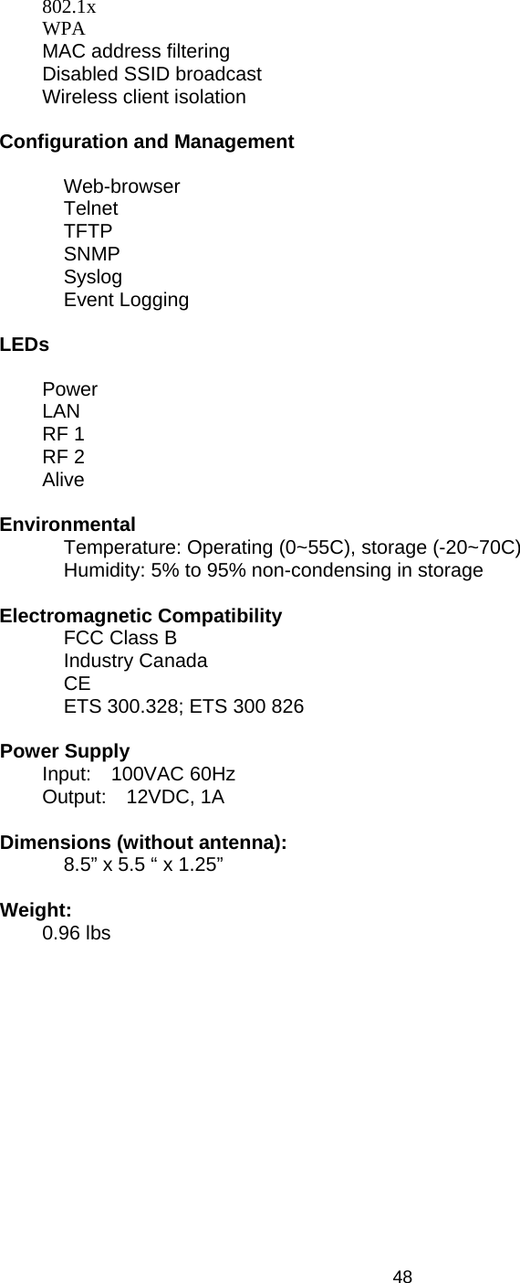
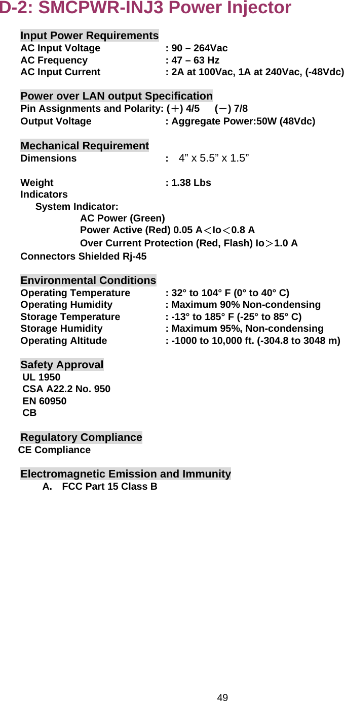
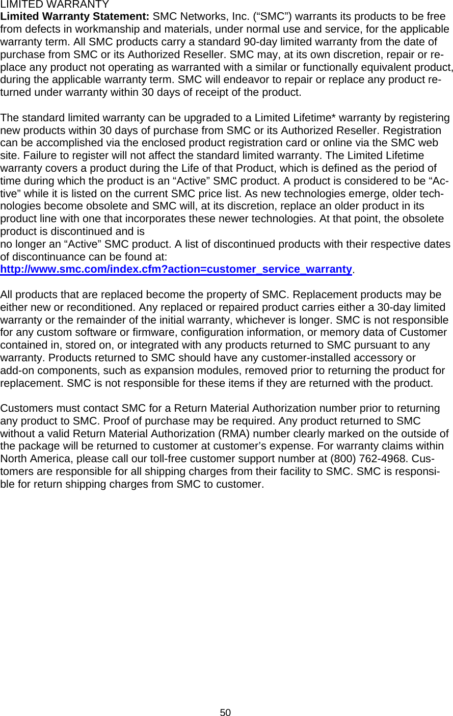
Users Manual
Navigation menu
Upload a User Manual
Namespaces
Wiki Guide
HTML
PDF
Info
Views
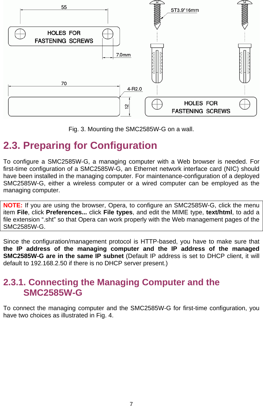
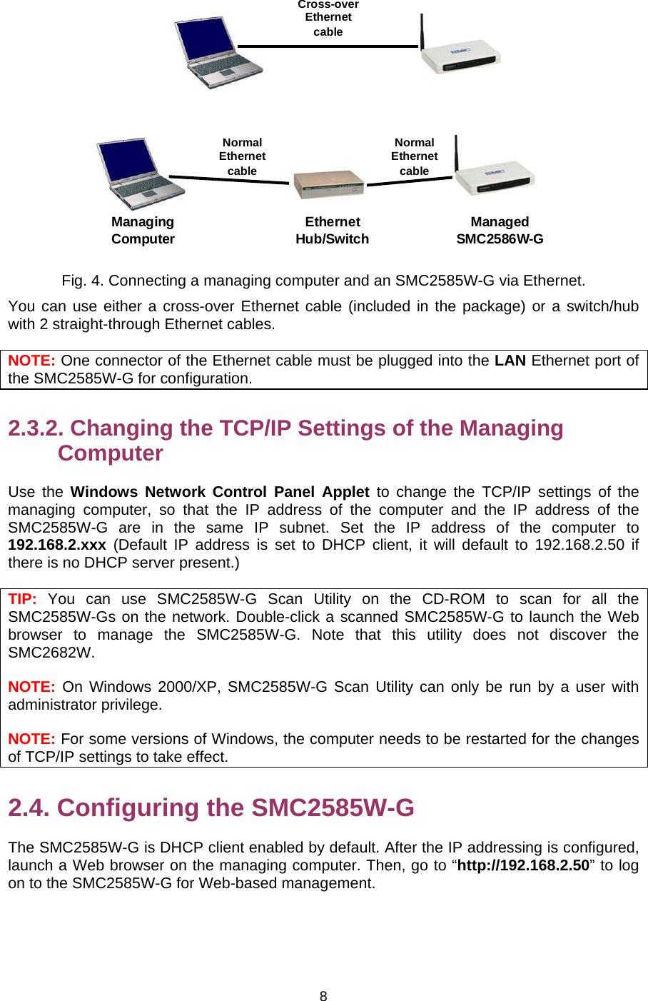
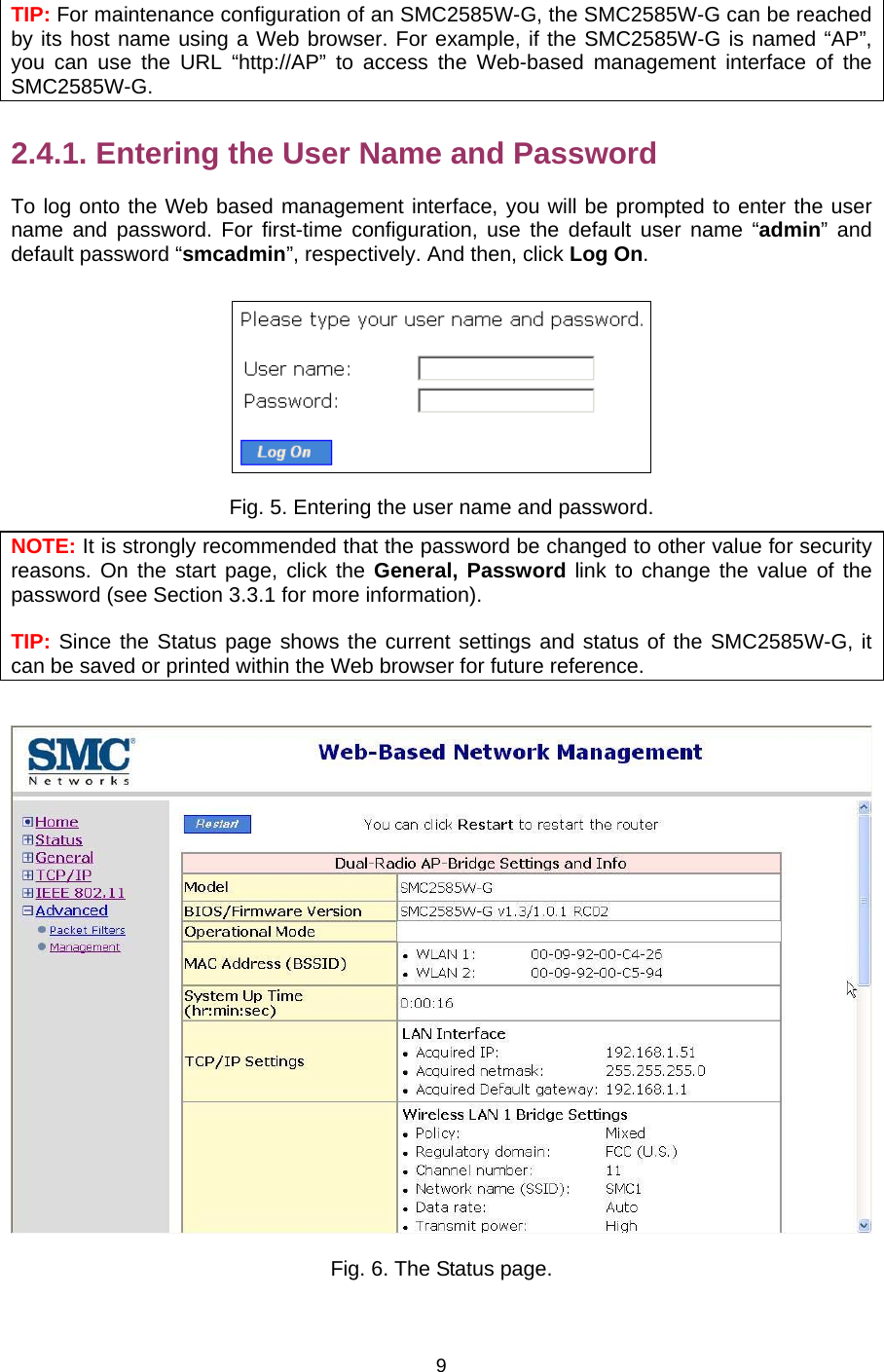
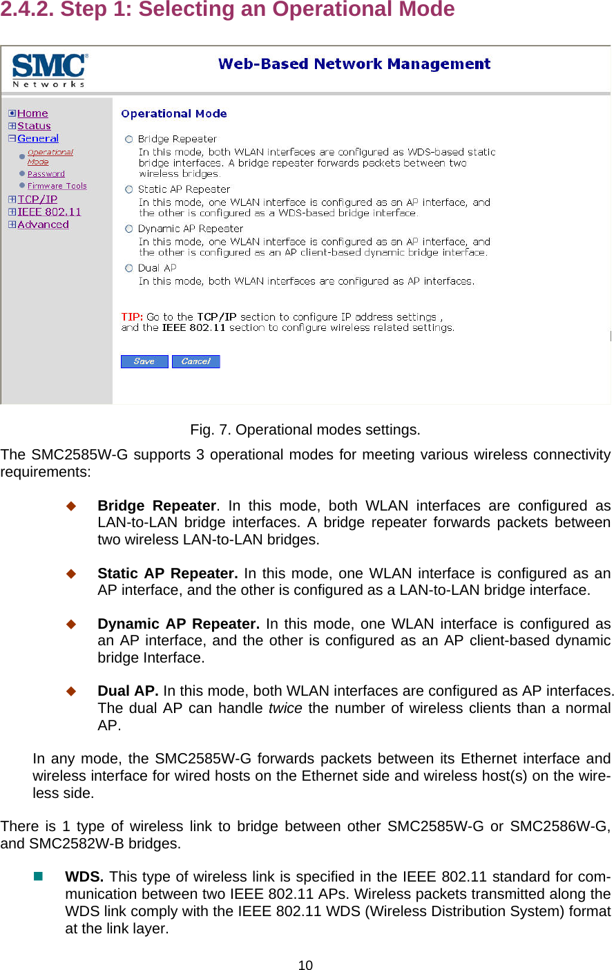
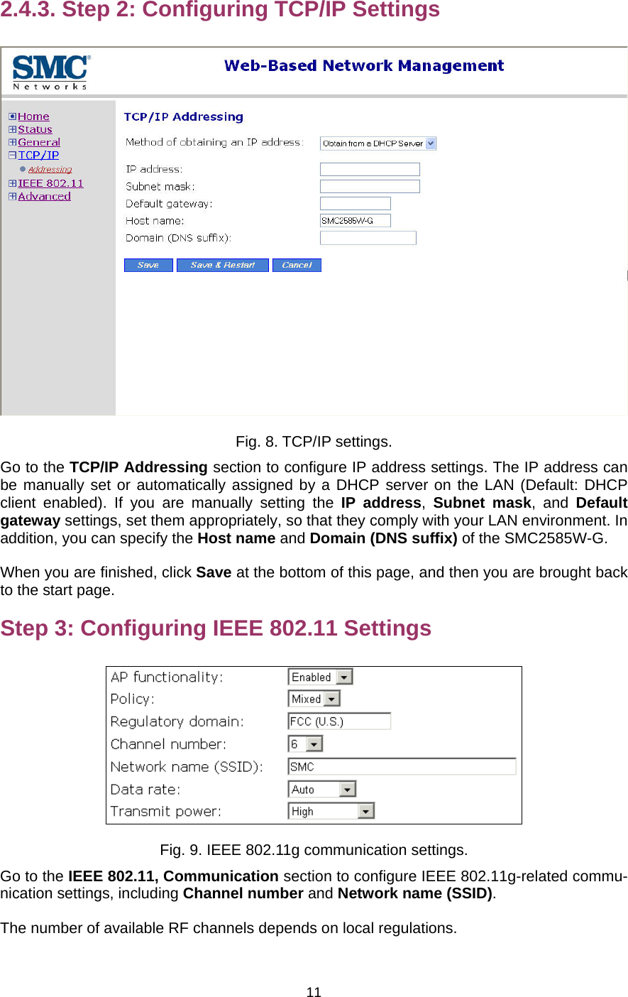
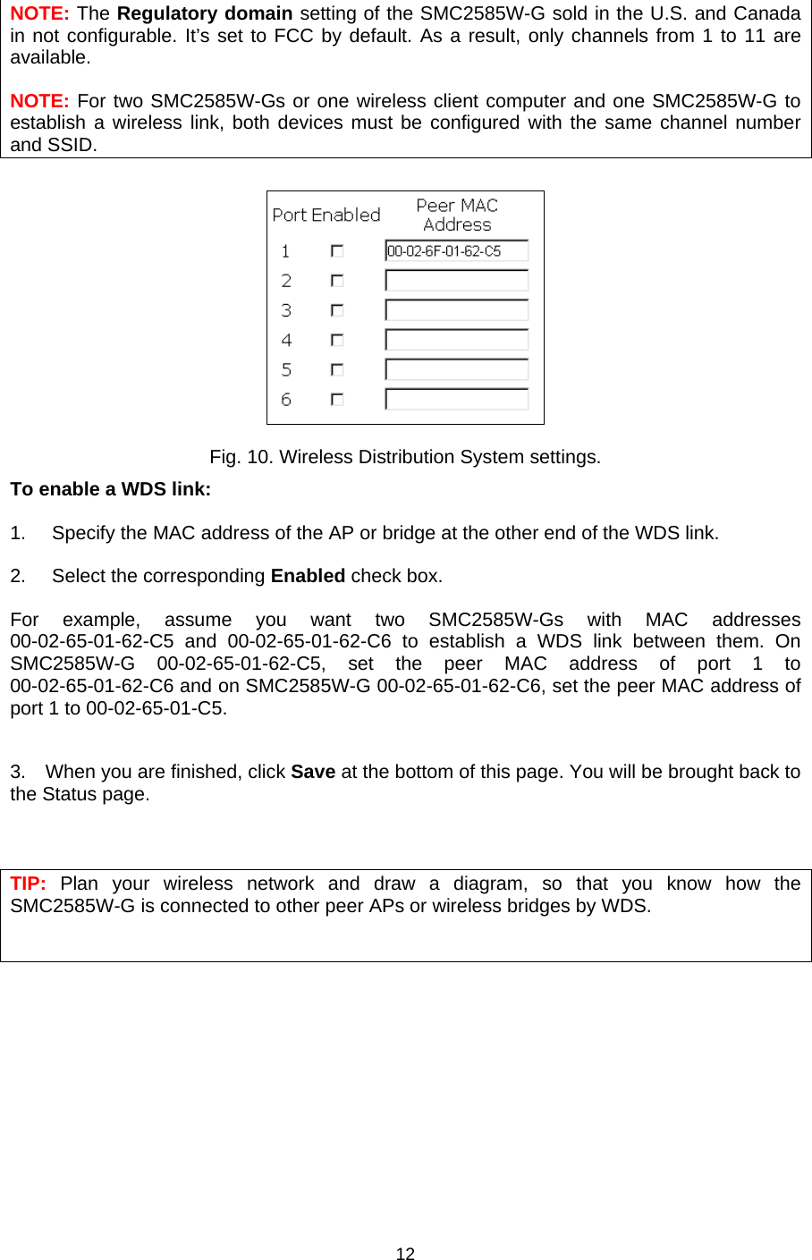
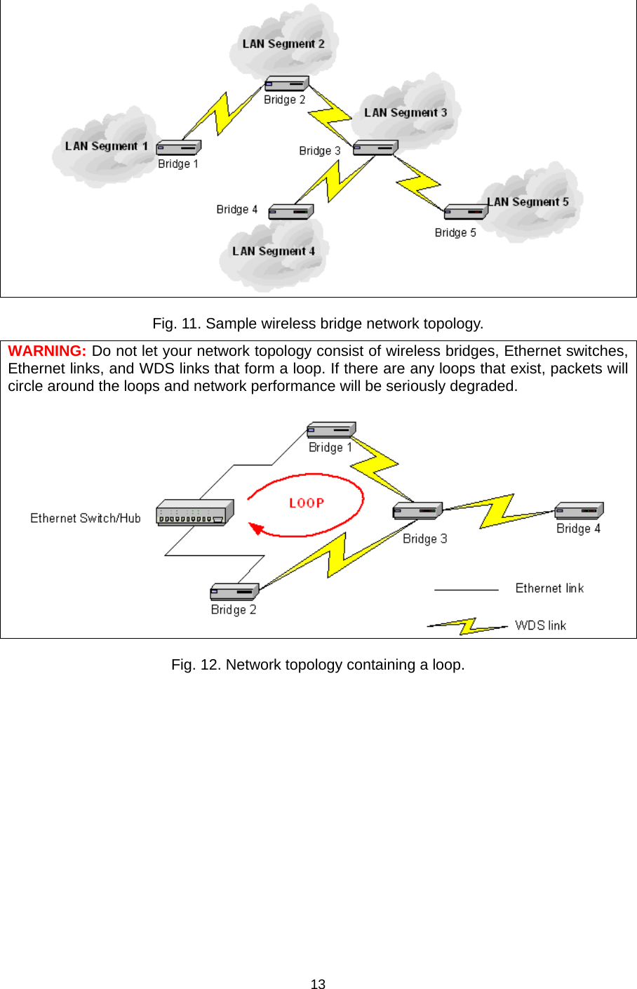
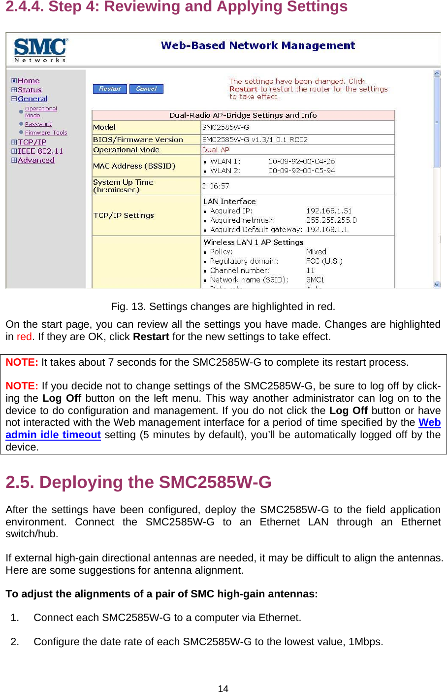
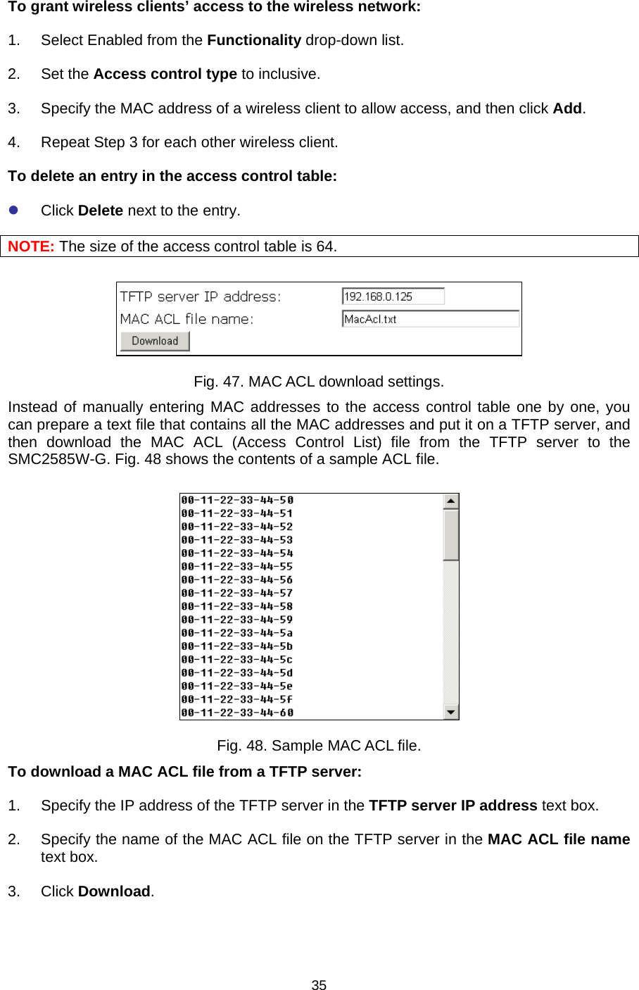
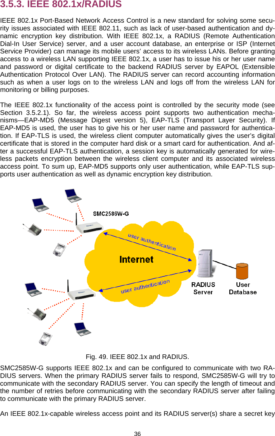
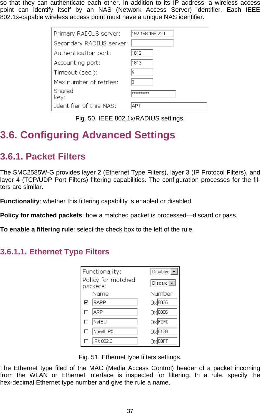
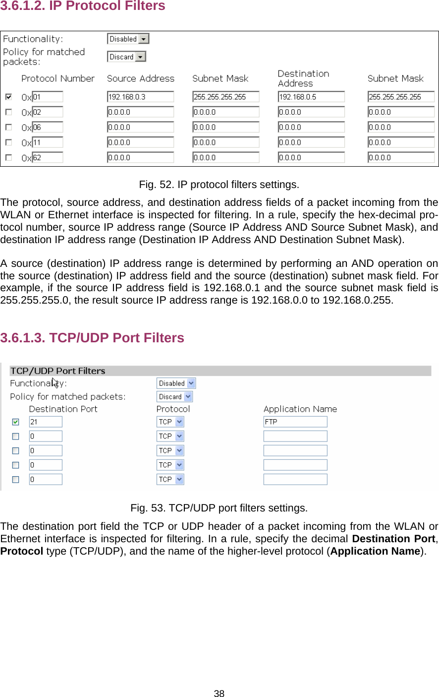
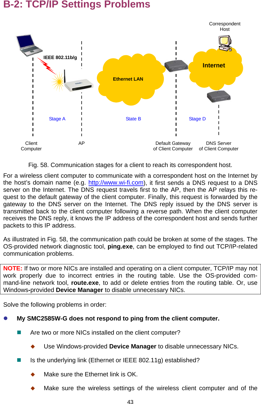
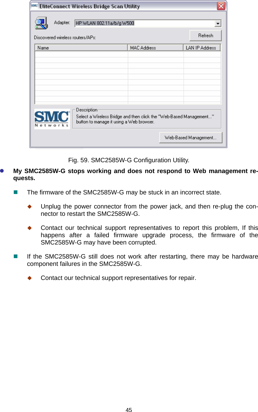
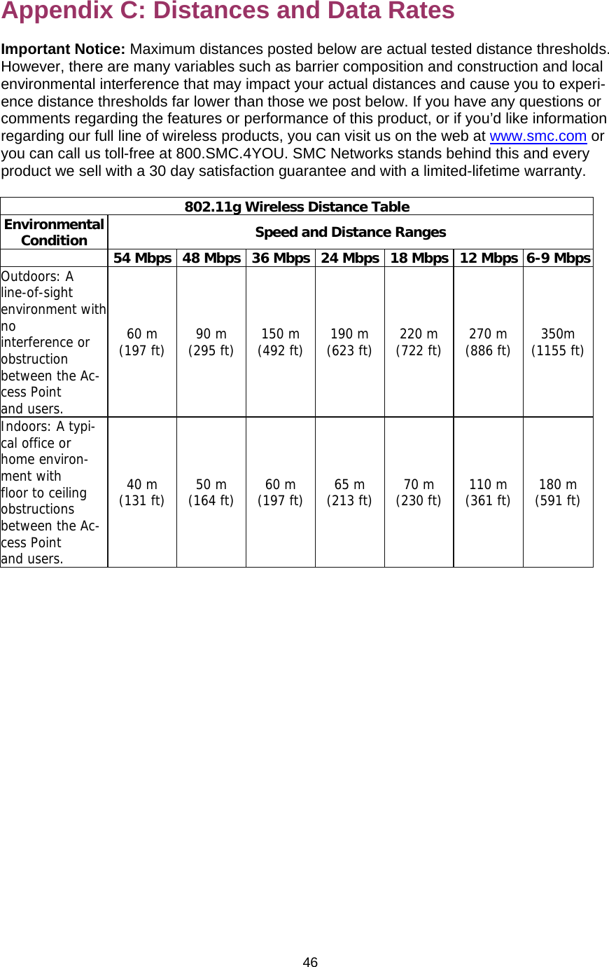
User Manual
Discussion / Help
Navigation