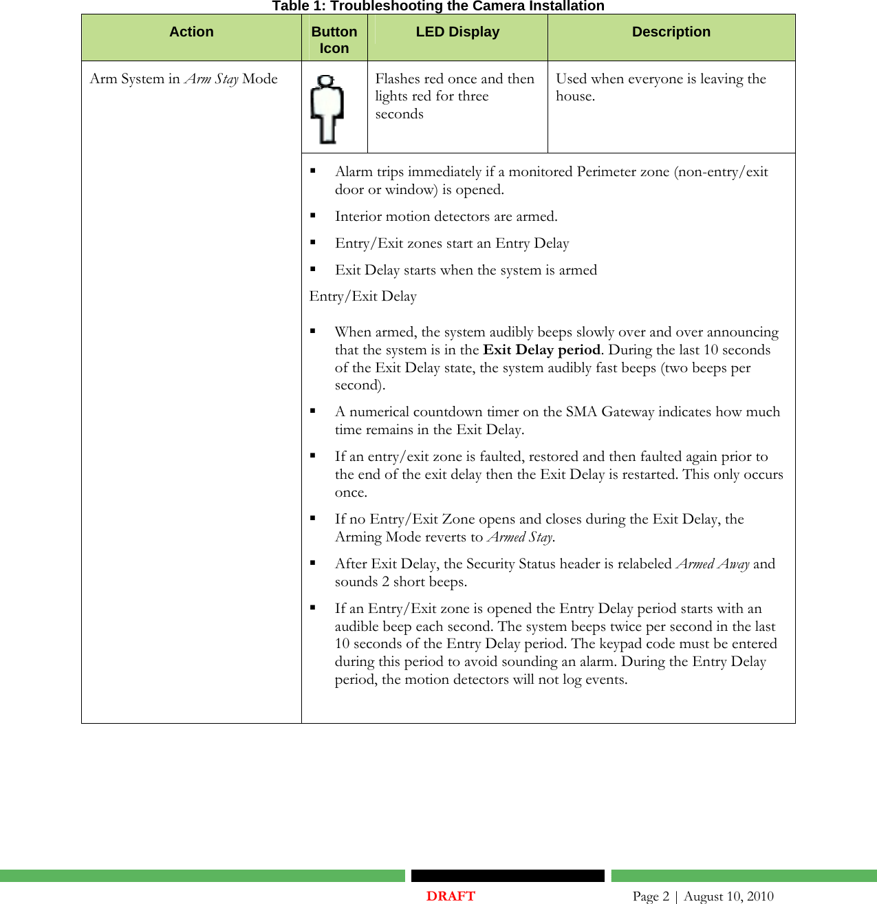
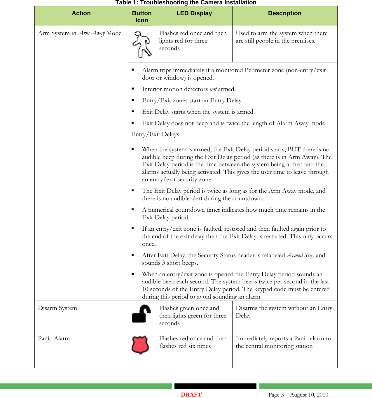
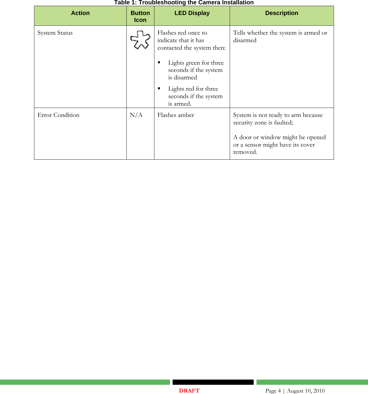
SMC Networks SMCKF01Z Zigbee Enabled Keyfob User Manual 1

SMC Networks Inc Zigbee Enabled Keyfob 1

Contents

User manual 1

         uControl User Guide Key Fob   Draft  April, 2010
      © 2006, 2007, 2008, 2009, 2010 uControl, Inc. The uControl logo, uControl, Inc., and all other uControl products and technology names are trademarks or registered trademarks of uControl, Inc. All other products or services mentioned herein are trademarks of their respective companies.
   DRAFT       Page iii | August 10, 2010  Table of Contents UNDERSTANDING AND USING THE KEY FOB ......................................................................................... 1ADDING KEY FOBS TO SYSTEM ................................................................................................................ 5SETTING A KEY FOB TO DEFAULT........................................................................................................... 8
   DRAFT       Page 1 | August 10, 2010  Understanding and Using the Key Fob A key fob is a mobile tool that lets you arm and disarm your system with the touch of a button. To use the key fob, press the button approximately 1.5 seconds until the LED flashes. See Table 1 for more information.    KNOWN ISSUE: Management Portal might not show all key fobs in the System Status → Peripherals tab.
   DRAFT       Page 2 | August 10, 2010   Table 1: Troubleshooting the Camera Installation Action  Button Icon  LED Display  Description  Flashes red once and then lights red for three seconds Used when everyone is leaving the house. Arm System in Arm Stay Mode  Alarm trips immediately if a monitored Perimeter zone (non-entry/exit door or window) is opened.  Interior motion detectors are armed.  Entry/Exit zones start an Entry Delay   Exit Delay starts when the system is armed  Entry/Exit Delay  When armed, the system audibly beeps slowly over and over announcing that the system is in the Exit Delay period. During the last 10 seconds of the Exit Delay state, the system audibly fast beeps (two beeps per second).  A numerical countdown timer on the SMA Gateway indicates how much time remains in the Exit Delay.   If an entry/exit zone is faulted, restored and then faulted again prior to the end of the exit delay then the Exit Delay is restarted. This only occurs once.   If no Entry/Exit Zone opens and closes during the Exit Delay, the Arming Mode reverts to Armed Stay.    After Exit Delay, the Security Status header is relabeled Armed Away and sounds 2 short beeps.   If an Entry/Exit zone is opened the Entry Delay period starts with an audible beep each second. The system beeps twice per second in the last 10 seconds of the Entry Delay period. The keypad code must be entered during this period to avoid sounding an alarm. During the Entry Delay period, the motion detectors will not log events.
   DRAFT       Page 3 | August 10, 2010  Table 1: Troubleshooting the Camera Installation Action  Button Icon  LED Display  Description Flashes red once and then lights red for three seconds Used to arm the system when there are still people in the premises. Arm System in Arm Away Mode  Alarm trips immediately if a monitored Perimeter zone (non-entry/exit door or window) is opened.  Interior motion detectors not armed.  Entry/Exit zones start an Entry Delay   Exit Delay starts when the system is armed.   Exit Delay does not beep and is twice the length of Alarm Away mode Entry/Exit Delays  When the system is armed, the Exit Delay period starts, BUT there is no audible beep during the Exit Delay period (as there is in Arm Away). The Exit Delay period is the time between the system being armed and the alarms actually being activated. This gives the user time to leave through an entry/exit security zone.   The Exit Delay period is twice as long as for the Arm Away mode, and there is no audible alert during the countdown.  A numerical countdown timer indicates how much time remains in the Exit Delay period.   If an entry/exit zone is faulted, restored and then faulted again prior to the end of the exit delay then the Exit Delay is restarted. This only occurs once.   After Exit Delay, the Security Status header is relabeled Armed Stay and sounds 3 short beeps.  When an entry/exit zone is opened the Entry Delay period sounds an audible beep each second. The system beeps twice per second in the last 10 seconds of the Entry Delay period. The keypad code must be entered during this period to avoid sounding an alarm. Disarm System  Flashes green once and then lights green for three seconds Disarms the system without an Entry Delay Panic Alarm  Flashes red once and then flashes red six times Immediately reports a Panic alarm to the central monitoring station
   DRAFT       Page 4 | August 10, 2010  Table 1: Troubleshooting the Camera Installation Action  Button Icon  LED Display  Description System Status  Flashes red once to indicate that it has contacted the system then:  Lights green for three seconds if the system is disarmed  Lights red for three seconds if the system is armed. Tells whether the system is armed or disarmed Error Condition  N/A  Flashes amber   System is not ready to arm because security zone is faulted;  A door or window might be opened or a sensor might have its cover removed.
   DRAFT       Page 5 | August 10, 2010  Adding Key Fobs to System  When a uControl key fob is removed from the box, it is already defaulted and ready to add to the SMA system.   To add (pair) a key fob to an SMA Gateway: 1. After Activation: a. Log into the Settings widget using the Installer key pad code. b. Touch Key Fobs & Pads → Add Key Fob. During the Activation process: Eventually the Add Key Fob screen is displayed in the TouchScreen, Touch No I do not want to add a Key Fob and then Next to skip this step. Touch Yes I want to add a Key Fob and then Next to begin the process to find and pair a key fobs to the SMA Gateway. CAUTION: If you choose not to add a key fob, the Add Key Pads screen is displayed. The Add Key Fob screen is very similar in appearance to the Add Key Pads screen. Be careful that you do not accidently pass through to the following Adding a Camera step unless you want to. The Locating Key Fobs screen is displayed.
   DRAFT       Page 6 | August 10, 2010  2. Install the battery in the key fob. Img_1424.mov  Figure 1: Double-click to View Example of How to Install the Battery The LED blinks several times every five seconds. This means that the key fob is in Search mode and can be paired with the SMA Gateway device.  Img_1425.mov Figure 2: Double-click to View Example of Key Fob in Search Mode If the key fob does not blink, it means that:  The key fob is not defaulted (see page 8 for how to default the device).  The battery is not securely installed in the device 3. If the green LED is stops blinking, it means the key fob has stopped Search mode to save battery power. Press any key fob button to restart Search mode. 4. If the key fob does not return to Search mode when you press a button, ensure the battery has not become displaced. 5. Follow the instructions in the Locating Key Fobs screen and click Next to add the key fob.  IMPORTANT: While pairing key fobs, ensure no sensors that have not been added to the system are faulted. This might cause the key fob or the sensors to fail to pair. The SMA Gateway begins searching for key fob devices in Search mode. 6. As each key fob is located by the device, a Key Fob icon is displayed on the screen.  7. Touch a Key Fob icon to pair the associated key fob with the SMA Gateway. 8. After all the devices are paired, touch Stop. The Wireless Key Fobs Located screen is displayed. 9. Click Next. The Configure Wireless Key Fobs screen is displayed.
   DRAFT       Page 7 | August 10, 2010  10. Touch the icon of a key fob that needs configuring. A keyboard screen is displayed to type a name for zone of the selected key fob.  11. Touch Done to enter the new name.  The Configure Wireless Key Fobs screen is displayed again. 12. Repeat steps 10 through 11 for each key fob. 13. Click Next to continue. If you are adding the key fobs after Activation, the Settings widget menu is displayed. If you are adding the key fobs during Activation, the Add Key Pads screen is displayed.
   DRAFT       Page 8 | August 10, 2010  Setting a Key Fob to Default Note: The SMA Gateway can only locate key fobs that are in Search mode and not currently paired with it. After a couple minutes, the key fob will drop out of Search mode to save battery power. If this happens, you will have to restart this procedure. To set a key fob to factory defaults: 1. If the key fob has already been added (paired) to the current TouchScreen, delete it (see page 10) 2. Gently pry the case apart and remove the PCB 3. Remove the battery and the button pad.  On the PCB side that is opposite the battery bed are the gold contacts that the buttons depress.  4. Line up the rubber buttons with the contacts  Note: The red Arm button is located nearest the beveled end of the PCB.  5. Replace battery while holding down the center button (‘*’), and one other button (recommended: Disarm button). The LED on the side of the PCB opposite of the battery flashes GREEN every five seconds. The key fob is in Search mode and ready to be paired (added) to an SMA Gateway.  6. Replace PCB and snap case back together. The key fob is ready to be located and paired with the SMA Gateway.
   DRAFT       Page 9 | August 10, 2010  Img_1424.mov  Figure 3: Double-click to View an Example How to Default a Key Fob
   DRAFT       Page 10 | August 10, 2010  Delete a Key Fob from the SMA System To delete a key fob from the SMA system: 1. From the Installer Settings Menu, touch Key Fobs & Sirens → Delete Key Fob. The Delete a Key Fob screen is displayed with images representing the key fobs currently installed to the SMA system. 2. Touch the image for the installed camera. A confirmation message is displayed: Are you sure you want to delete <Key Fob name>. 3. Touch Yes. The key fob image is removed from the Delete a Key Fob screen.

Navigation menu